

J. Cent. South Univ. (2021) 28: 1493-1504
DOI: https://doi.org/10.1007/s11771-021-4717-7

Electro-osmotic chemical behavior of clayey soil under various boundary conditions
XUE Zhi-jia(Ѧ־��)1, 2, XIONG Qi(����)1
1.School of Highway,Chang��an University,Xi��an 710064,China;
2.State Key Laboratory of Coastal and Offshore Engineering,Dalian University of Technology,Dalian 116024,China
 Central South University Press and Springer-Verlag GmbH Germany, part of Springer Nature 2021
Abstract:
The use of electro-osmotic chemical is an effective method to improve the clayey soil foundation. Various boundary conditions can be adopted in this method. In this work, two electrode�Cclay contacts, three solution conditioners, and four anode solution supply times were used for clayey soil improvement. Based on the experimental data, electro-osmotic consolidation theory, and transport of ion theory, it is found that the electro-osmotic chemical effect of the separation of electrode�Cclay (E_S) is more beneficial for the transport of Ca2+, production of cementing material, and reduction of water content than that of electrode�Cclay (E_C) joining; through electrode�Cclay contact separation, the anode solution conditioner (NaPO3)6 (E_SHMP) delayed the cementing reaction and then increased the transport of Ca2+ near the cathode, which increased the amount of cementing material and the electro-osmotic chemical effect; and when the anode conditioner (NaPO3)6 was used, two days of anode solution supply followed by three days cut off from the anode solution led to the highest undrained shear strength increase after the application of electro-osmotic chemical, which resolved the uneven electro-osmotic chemical effect in the E_SHMP.
Key words:
Cite this article as:
XUE Zhi-jia, XIONG Qi. Electro-osmotic chemical behavior of clayey soil under various boundary conditions [J]. Journal of Central South University, 2021, 28(5): 1493-1504.
DOI:https://dx.doi.org/https://doi.org/10.1007/s11771-021-4717-71 Introduction
Electro-osmotic consolidation is an effective method to improve the soil foundation, which was first adopted for German roadbed reinforcement by Cassagrande. A series of successful case studies using electro-osmotic consolidation have been reported, including reclamation engineering in Wenzhou, China [1], subgrade dewatering in Canada [2], and reclamation engineering in Singapore [3, 4]. In addition, some scholars have explored the influences of the electrical potential gradient [5], pressure loading [6], electrode arrangement [7], and electrode materials [8] on the electro-osmotic consolidation effect.
LEFEBVRE et al [9] injected saline solution into soil in an anode tube, which increased the soil conductivity at the anode�Csoil contact point (the contact surface between the anode and soil), and this increased the effective electrical potential gradient of the soil sample. The effective electrical potential gradient increase promoted the electro-osmosis consolidation effect. OZKAN et al [10] used Al3+ and PO43- to stabilize kaolinite and found that the undrained shear strength of kaolinite increased by 500%-600% compared with the initial values. In addition, scholars have investigated the electro-osmotic chemical effect on soil of various saline solutions. ALSHAWABKEH et al [11] also used electro-osmotic chemical with H3PO4 solution to increase the shear strength of Boston Blue clayey soil. They reported that cementing contributed to an increase in shear strength, while OTSUKI et al [12] compared the following combinations (anode solution�Ccathode solution mode): AgNO3�CNaOH, Mg(CH3COO)2�CNaOH, ZnSO4�CNa2CO3, and Mg(CH3COO)2�CNa2CO3. They found that Mg(CH3COO)2�CNa2CO3 provided the optimal electro-osmotic chemical reinforcement effect.
OU et al [13] injected CaCl2 solution into Taipei clayey soil using electro-osmotic chemical and found that the average shear strength of the treated clayey soil was almost 500% higher than that in the untreated clayey soil. CHIEN et al [14] added CaCl2 and NaSiO3 into clayey soil from the anode using electro-osmotic chemical, and an area of stiffness was observed near the anode. MOHAMEDELHASSAN et al [15] injected Ca2+ and Al3+ into calcareous soil using the electro-osmotic chemical method and monitored the pH, Ca2+ concentration, and Al3+ concentration of the discharge. This research can guide the use of electro-osmotic chemical reinforcement on marine soil foundations. AYODELE et al [16] used CaCl2 in the anode chamber and H3PO4 in the cathode chamber to improve the laterite using electro-osmotic chemical. After treatment, no significant change was observed for the water content of laterite, but the shear strength of laterite increased obviously. This was mainly because the cementing material Ca5(PO4)3OH(s) increased the shear strength of the laterite.
In laboratory experiments on the electro-osmotic chemical, two electrode�Csoil contact types are used: 1) electrodes can be inserted into chamber solutions, which means that the electrodes are physically separated from the clayey soil sample [17]; and 2) electrodes can be directly inserted into the clayey soil, which means that the electrodes are in physical contact with the clayey soil sample. In the case of type 1), current goes through the solution and is then applied to the clayey soil sample. In Refs. [11, 18, 19], this kind of electrode�Csoil contact was adopted. In the case of type 2), current is directly applied to the clayey soil sample. In Refs. [20-22], this kind of electrode�Csoil contact was used. However, it has been rare for studies to directly compare the electro-osmotic chemical effects of these two electrode-soil contacts.
To increase the electro-osmotic method effect, ASAVADORNDEJA et al [23] adopted an anode depolarization method to maintain an alkaline environment (pH=10), which was beneficial for the production of cementing material in the clayey soil sample. However, the maintenance of a constant solution pH value is very complex in practical applications. OU et al [24] injected CaCl2, KOH, a fresh sodium silicate solution and deionized water into clayey soil using electro-osmotic chemical, which improved the shear strength of the entire clayey soil sample effectively. The injection of deionized water was beneficial for the transport of Ca2+ and a highly alkaline condition product near the cathode, leading to an increase in the pozzolanic reaction amount and an increase in the clayey soil shear strength. Solution conditioners can improve the function of the anode solution or cathode solution. However, solution conditioners are seldom adopted to increase the electro-osmotic chemical reinforcement effect.
There are two kinds of anode solution supply modes: one is to cut off the anode solution after a period of anode solution supply; the other is to supply the anode solution from beginning to end (BTE). To be specific, OU et al [13] and CHIEN et al [25] injected a certain amount of CaCl2 solution using the electro-osmotic chemical method and then conducted an electro-osmotic experiment without an anode solution supply. These two studies increased the positive ion concentration in the pore water and then increased the electro-osmotic drainage volume. The shear strength of the nearby anode area was much higher than that of the nearby cathode area. On the other hand, XUE et al [17] and OU et al [26] supplied Ca2+ solution from beginning to end. Under exposure to direct current, Ca2+ was transported from the anode to the cathode and then the cementing material was precipitated near the cathode, which increased the soil foundation.
To reduce the reinforcement effect difference between the nearby anode area and the nearby cathode area, ASAVADORNDEJA et al [23] maintained a constant pH value for CaCl2 solution (anode solution), which was beneficial for the cementing reaction throughout the whole clayey soil sample. OU et al [24] injected CaCl2, KOH and Na2SiO3, and distilled water into clayey soil. The electro-osmotic injection of distilled water was beneficial for the transport of Ca2+, and the pH increased near the cathode, improving the shear strength of clayey soil effectively. CHIEN et al [27] injected a certain amount of CaCl2 solution and then cut off the anode solution. From the clayey soil reinforcement results, they found a suitable supply time for the anode solution. If the experiment supplied a superfluous amount of CaCl2 solution, the cementing material blocked the pore channels of clayey soil near the cathode, which decreased the following water content reduction. If the experiment supplied an inadequate amount of CaCl2 solution, there was insufficient cementing material product in the clayey soil. Therefore, there is a suitable supply time for anode solution when using electro-osmotic chemical.
To determine the optimum electro-osmotic chemical technique for clayey soil improvement, this paper conducted a series of electro-osmotic chemical experiments, including two electrode�Cclay contacts, three solution conditioners (CaCO3 in the anode solution, (NaPO3)6 in the cathode solution, and no conditioner), and four anode solution supply times. During the electro-osmotic chemical experiments, the current, drainage volume, and electrical potential distribution were monitored. After the electro-osmotic chemical experiments, the calcium content, undrained shear strength, and water content were measured. Based on the relevant theories and electro-osmotic chemical data, this paper determined the optimum electro-osmotic chemical technique and explored the clayey soil improvement mechanism under various boundary conditions.
2 Materials and methods
2.1 Description of clayey soil
The clayey soil sample was collected from Dalian field, China. The clayey soil sample underwent pretreatment processes to satisfy the demands of the electro-osmotic chemical experiment, including an air-drying procedure and a pulverization procedure. The liquid limit and the plastic limit were 43.7% and 22.2%, respectively. According to the unified soil classification system (USCS), the clayey soil sample belongs to the CL scope (low plastic clayey soil). Based on the method used in Ref. [28], the initial pH value of the clayey soil sample was 6.4. Because the clayey soil sample was collected from a coastal region, it was necessary to measure the salt content of the clayey soil sample. The salt content was determined to be 0.93% based on the method presented in the standard SL237-1997. To determine the chemical element composition and clayey soil minerals, this paper adopted X-fluorescence spectrometer (XRF) and X-ray diffraction (XRD) methods to measure the clayey soil powder. As seen from the data in Table 1, the contents of kaolinite, illite, and montmorillonite were 67%, 14%, and 4%, respectively. The grain size distribution curve is shown in Figure 1. The <75 ��m fraction corresponds to 100%, and the <5 ��m fraction corresponds to 45.8%.
2.2 Experimental apparatus
To satisfy the research demands, this paper designed and manufactured an electro-osmotic chemical experimental system that included an electro-osmotic chemical cell and a data monitor system. The experimental system is shown in Figure 2(a).
The electro-osmotic chemical cell included the following functions: an electrode�Cclay contact arrangement and an anode solution supply time change. The electro-osmotic chemical cell was divided into the anode chamber, clayey soil chamber, and cathode chamber by two gates. The anode chamber was connected to a solution supply tank, which was used to supply the anode solution. The clayey soil chamber was filled with the clayey soil sample, and the cathode chamber was filled with the cathode solution. Electrical potential measurement ports were set in the clayey soil chamber wall and were used to insert the electrical potential measurement stainless steel wire. An overflow hole in the cathode chamber was used to drain the discharge during the experiments. In addition, the pressure loading on the clayey soil sample was supplied by a pressure plate and weights.
Table 1 Clayey soil properties and mineral and chemical composition [17]


Figure1 Grain size distribution of clayey soil
The data monitoring system was able to monitor the current, drainage volume, settlement, and electrical potential. The current sensor (XIANMIAO,0-1000 mA) was connected between the power supply and the anode. The drainage volume was measured by a measuring cylinder. The settlement was monitored with a displacement sensor (MILANG, 0-10 mm). The electrical potential was measured with a voltmeter.
2.3 Experimental procedures
This paper conducted a series of electro-osmotic chemical experiments and related measurement experiments. The experimental plan of electro-osmotic chemical experiments is shown in Table 2, including the test number, electrode�Cclay contacts, solution conditioner conditions, and anode solution supply modes.
In addition, measured variables included the calcium content, water content, and undrained shear strength, as shown in Table 3. The specific experimental procedures were as follows:
1) Following the experimental plan in Table 2, E_C used the electrode arrangement in Figure 2(b), three tests (E_S, E_Ca, E_SHMP) used the electrode arrangement in Figure 2(c), and E_1_4, E_2_3, and E_3_2 used the electrode arrangement in Figure 2(d). We smeared vaseline on the internal surface of the clayey soil chamber. Then, we poured the slurry sample into the clayey soil chamber and conducted a vibration process to remove air bubbles from the slurry sample. We put filter paper and geotextile on the slurry sample. After that, a pressure plate and a weight were put on the geotextile to carry out clayey soil consolidation until the settlement reached a stable situation.
2) Then, we filled the solution tank, anode chamber, and cathode chamber with the corresponding solutions following the experimental plan presented in Table 2. We turned on the power supply to carry out the electro-osmotic chemical experiments and used the data monitoring system to monitor the current drainage volume. The anode solution supply time was 7200 min in E_C, E_S, E_Ca, and E_SHMP. For E_1_4, the anode solution supply time was the first 1440 min (0-1440 min), and the anode solution was cut off from 1440 to 7200 min.

Figure 2 Electro-osmotic chemical experimental system (a), separation of electrode-clay (b), joining of electrode-clay (c) and E_1_4 arrangement (d)
Table 2 Experimental plan of electro-osmotic chemical experiments

Table 3 Experimental plan of measurement experiments
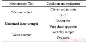
3) After the electro-osmotic chemical experiments, a vane shear apparatus was used to measure the undrained shear strength at distances of 2.5, 7.5, 12.5, 17.5 and 22.5 cm from the anode. After that, the clayey soil samples were divided uniformly into five measurement samples. We measured the water content of one of the clayey soil samples based on the standard SL237-1999. The remaining parts were subjected to an air-drying procedure and pulverized with a mallet into powder. In addition, this paper adopted XRF technology to measure the calcium content of the clayey soil.
3 Results and discussion
3.1 Electrical potential distribution
As seen in Figure 3(a), the electrical potential distribution of the two electrode�Cclay contacts had an approximately linear distribution at the beginning of the electro-osmotic chemical experiments. The voltage between V1 and V6 of E_C was higher than that of E_S at the beginning of the electro-osmotic chemical experiment. This was mainly because the electrodes were in direct contact with the clayey soil sample in the case of E_C, and there was a solution media between the electrodes and the clayey soil sample in the case of E_S.
As seen from Figure 3(a), after 1440 min of the electro-osmotic chemical experiment, the V1 electrical potential of E_Ca was much lower than that under other conditions. In contrast, the electrical potential distribution showed a similar distribution trend under E_S and E_SHMP. After 1440 min of the electro-osmotic chemical experiment, the V1 electrical potential of E_Ca increased. However, there was almost no difference in the electrical potential distribution between E_S and E_SHMP from 1440 to 2880 min. As seen from Figure 3(b), after 7200 min of the electro-osmotic chemical experiment, the voltage between V6 and the cathode of E_SHMP was much higher than that of E_S. In addition, this paper observed white cementing material in the holes of the cathode gate, which is shown in Figure 3(d). However, white cementing material was not obvious in the case of E_S. The white cementing material increased the voltage between V6 and the cathode. Similarly, the observation of white cementing material proved that the amount of cementing material in E_SHMP was much greater than that in E_S. This is evident that (NaPO3)6 increased the amount of cementing material in the clayey soil sample.
As seen from Figures 3(a) and (b), after 1440 min of electro-osmotic chemical experiments, the anode solution was cut off and the anode�Cclay contact type changed into the situation shown in Figure 2(c). The existing Ca2+ gathered at the anode in the first 1440 min [17] and was transported from the anode to the cathode by the direct current. In addition, the water content near the anode was reduced by the electro-osmotic consolidation contribution (which will be discussed in Section 3.3). Therefore, the voltage difference between V1�CV3 and V4�CV6 became smaller and smaller after 1440 min in E_1_4.

Figure 3 Electrical potential distributions between 0 and 2880 min (a), between 4320 and 7200 min (b), between 5760 and 7200 min (c) and white cementing material in cathode gate of E_SHMP (d)
Figure 3(c) shows the electrical potential distribution under four anode solution supply time at 5760 and 7200 min. The results show that the longer the supply time of the anode solution was, the smaller the voltage of V1�CV3 was, and the greater the voltage of the V4-cathode was. In addition, the voltage of the V6-cathode increased as the electro-osmotic chemical experiment progressed. In the case of E_3_2, the voltage of the V6 cathode increased from 5760 min to the end of the electro-osmotic experiment (at 7200 min), which was mainly because there was cementing material blocking the channel of the gate. The existence of cementing material in these areas caused the high electrical resistivity area product between V6 and the cathode.
3.2 Electro-osmotic flow rate and current
The electro-osmotic flow rate is the drainage volume per unit of time, which can be expressed by:
Qe=keieA=V/��t (1)
where Qe is the electro-osmotic flow rate; ke is the electro-osmotic permeability coefficient; ie is the electrical potential gradient; A is the clayey soil sample cross section area; V is the drainage volume, and ��t is the electro-osmotic drainage volume monitor interval.
Figure 4 shows the change in the electro-osmotic flow rate over time. At the initial stage, the electro-osmotic flow rate of E_S was almost the same as that of E_SHMP. As seen from Eq. (1), the electro-osmotic flow rate was directly proportional to the electrical potential gradient ie. The clayey soil sample external voltage (electrical potential gradient ie) of E_Ca was almost 50% that of the other two experiments (E_S and E_SHMP 1440 min experimental data). Thus, the electro-osmotic flow rate of E_Ca was much lower than those of E_S and E_SHMP at the initial stage. After that, the three electro-osmotic flow rate trends showed differences.

Figure 4 Change in electro-osmotic flow rate over time under E_S, E_Ca, and E_SHMP
The electro-osmotic flow rate of E_SHMP was higher than that of E_S at the difference stage, which was mainly because (NaPO3)6 delayed the cementing reaction and then extended the unblocked electro-osmotic flow channel time. There was greater Ca2+ transport into the clayey soil sample in the difference stage of E_SHMP (which will be discussed in Section 3.4).
In addition, conditioner (NaPO3)6 can delay the cementing reaction without decreasing the amount of cementing material when other conditions are the same. After the difference stage, the amount of cementing material in E_SHMP was greater than that in E_S, which caused the electro-osmotic flow rate of E_SHMP to be lower than that of E_S after 5000 min. For the E_Ca, the porosity of the clayey soil sample in E_Ca was higher than that in the other two experiments (E_S and E_SHMP) at the difference stage (2000-5000 min), even though the external voltage (electrical potential gradient ie) of E_Ca was lower than that of other two experiments (E_S and E_SHMP). Based on Eq. (1), the electro-osmotic flow rate of E_Ca was similar to that of E_SHMP at the difference stage (2000-5000 min).
As shown in Figure 5, the current of E_C was higher than that of E_S at the initial stage. Specifically, the peak current value of E_C was higher than that of E_S. As the electro-osmotic chemical experiments proceeded, the average water content decreased and the cementing reaction proceeded, which reduced the porosity of the clayey soil sample. As a result, the current curve came into a sharp drop stage and then decreased to a stable value, as shown in Figure 5. In addition, the current value of E_S was higher than that of E_C in the sharp drop stage (1500-2000 min). This was mainly because the water content of E_S was higher than that of E_C (which will be discussed in Section 3.3).

Figure 5 Change in current over time under E_S, E_C, E_1_4, E_2_3, E_3_2, and E_SHMP
As shown in Figure 5, there were new peak current values after the anode solution was cut off in E_1_4, E_2_3, and E_3_2. This was mainly because the anode�Cclay joining increased the effective electrical gradient of the clayey soil sample and then increased the current value in a short period of time. After the new peak values of current were reached, the current decreased as the electro-osmotic experiment progressed, which was mainly due to the reduction in the water content of the clayey soil sample. There was still a constant anode solution supply in E_SHMP after 1440, 2880 and 4320 min, which caused the electrical conductivity of E_1_4, E_2_3, and E_3_2 to be lower than that of E_S. Therefore, the current curve of E_1_4 decreased more quickly than that of E_S between 1680 and 2100 min. In addition, the current in E_2_3 and E_3_2 also showed a fast deepening stage.
3.3 Water content
Because the total stress has a constant value in this paper, the effective stress was determined by the negative pore water pressure development. A reduction in water content is mainly caused by an increase in effective stress. Therefore, the reduction in water content was determined by the negative pore water pressure in this work [29].
The boundary condition, pore water pressure distribution, and reinforcement mechanism differed between the electro-osmotic consolidation and electro-osmotic chemical conditions. As shown in Figure 6(a), the anode boundary of the electro-osmotic consolidation experiment was impermeable, and the pore water pressure expression under stable conditions is given as [30, 31]:
 (2)
(2)
where kh is the hydraulic permeability coefficient; ��w is the unit weight; Um is the external voltage on the clayey soil sample; x is the distance to the cathode, and L is the clayey soil sample length. The absolute negative pore water pressure value decreased from the anode to the cathode, as shown in Figure 6(b). The increase in shear strength came from the reduction in water content during electro-osmotic consolidation. Therefore, shear strength always decreased from the anode to the cathode.
In contrast, the anode flow boundary of electro-osmotic chemicals is permeable, as shown in Figure 6(c), and there is no excess pore water pressure in the clayey soil sample if the electro-osmotic permeability coefficient ke is treated as a constant value. However, due to the pH changing during the application of electro-osmotic chemicals, there is a negative pore water pressure product in the clayey soil sample. The pore water pressure of electro-osmotic chemical expression is shown as [18]:

 (3)
(3)
where ke(x(pH),t) is the electro-osmotic permeability coefficient function. In previous studies,the pore water pressure point was calculated by Eq. (3) and then a pore water pressure regression curve was constructed. The pore water pressure distribution showed an arch distribution, as shown in Figure 6(d). Figure 7 shows the water content distribution under various boundary conditions. The water content distributions of E_C, E_S, E_Ca, and E_SHMP showed an arch distribution, which was due to the negative pore water pressure distribution shown in Figure 6(d). The average water content of E_C was higher than that of E_S. This was mainly because the cementing reaction of the E_C occurred earlier than that of E_S, and it weakened the negative pore water pressure development, which reduced the effective stress development and then decreased the water content reduction. Due to the low external voltage of E_Ca, the negative pore water pressure of E_Ca was lower than that in the other two experiments (E_S and E_SHMP). The average water content of E_Ca was higher than those of E_S and E_SHMP.
After the anode solution was cut off, the anode flow boundary changed from permeable to impermeable, and the negative pore water pressure of the anode position increased from 0 kPa to the maximum absolute pore water pressure value at this stage, as explained in Figures 6(c) and (d). Therefore, the water content of E_1_4 increased from the anode to the cathode, similar to what occurred in electro-osmotic consolidation, as shown in Figure 6(c). The water content ranking was E_1_4 < E_2_3 < E_3_2 < E_5_0 at a distance of 2.5 cm to the anode. This proved that the earlier the anode solution was cut off,the lower the water content at a distance of 2.5 cm to the anode was.
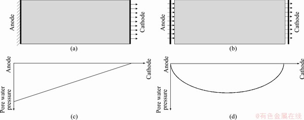
Figure 6 Flow boundary conditions during electro-osmotic consolidation (a) and electro-osmotic chemical treatment (b), diagrams of pore water pressure distribution during electro-osmotic consolidation (c) and after treatment with electro-osmotic chemical (d)

Figure 7 Water content distribution under various boundary conditions
The water content of E_1_4 and E_2_3 increased from the anode to the cathode, similar to what occurred in electro-osmotic consolidation. In contrast, the minimum water content of E_3_2 occurred in the middle of the clayey soil sample. This mainly proved that the long supply time of the anode solution already determined the negative pore water pressure distribution, which changed in a non-obvious manner after the anode solution was cut off.
3.4 Undrained shear strength
An increase in the undrained shear strength is mainly caused by a reduction in water content or by the water content reduction�Ccementing reaction [32]. The cementing reaction mainly occurs due to the chemical reaction of ions. In this paper, Ca2+ and H+ were transported from the anode to the cathode by electromigration and the fluid flux advection contributions. OH- and [�CSiO32-�C]n were transported from the cathode to the anode by electromigration, producing Ca(OH)2 and CSH (calcium silicate hydrated) near the cathode [17]. Because CSH is amorphous, it cannot be measured by XRD method.
Figure 8 shows the undrained shear strength under various boundary conditions. In the case of E_S, the average undrained shear strength at distances of 2.5, 7.5 and 12.5 cm to the anode was higher than that of E_C. This was mainly because the average water content of E_S was lower than that of E_C at these three positions. As seen from Figure 9, the calcium content of E_S was higher than that of E_C near the cathode. Therefore, a greater cementing reaction occurred in E_S than in E_C. The product of Ca(OH)2 and CSH cemented the soil particles and then increased the undrained shear strength of the clayey soil sample at these positions. Thus, the average undrained shear strength at distances to the anode of 17.5 and 22.5 cm was higher in E_S than in E_C.

Figure 8 Undrained shear strength distribution under various boundary conditions
The anode conditioner CaCO3 did not increase the clayey soil sample reinforcement effect. However, the cathode conditioner (NaPO3)6 delayed the cementing reaction and then increased the amount of cementing material in the clayey soil sample. In addition, we analyzed the undrained shear strength at specific positions. The average water content at distances to the anode of 2.5 and 7.5 cm was lower in E_SHMP than in E_S. This caused the average undrained shear strength of E_SHMP to be higher than that of E_S at these two positions. There was no obvious difference in the water content between E_SHMP and E_S at distances to the anode of 17.5 and 22.5 cm. However, the calcium content was higher in E_SHMP than in E_S near the cathode.

Figure 9 Calcium content near cathode under various boundary conditions
Section 3.2 discussed that the electro-osmotic flow rate of E_SHMP was higher than that of E_S at the difference stage. The delay in the cementing reaction increased the amount of Ca2+ transport in E_SHMP, which increased the amount of cementing material in the clayey soil sample and induced the production of white cementing material observed in the gate of E_SHMP. Therefore, the undrained shear strength values in E_S at distances to the anode of 17.5 and 22.5 cm were higher than the maximum undrained shear strength value in E_S. This shows that the (NaPO3)6 conditioner was beneficial as it increased the reinforcement effect.
Figure 8(b) shows the undrained shear strength distribution under four anode solution supply times in the electro-osmotic chemical experiment. Reduction of the water content in E_1_4 and E_2_3 increased the undrained shear strength at distances to the anode of 2.5 and 7.5 cm in comparison with that of E_SHMP. The undrained shear strength increase came from the reduction in water content and the production of cementing material in the electro-osmotic chemical experiment near the cathode [17]. The water content of E_1_4 was higher than that of E_2_3 at a distance to the anode of 22.5 cm, although the calcium content was similar in these two experiments. Therefore, the undrained shear strength of E_1_4 was lower than that of E_2_3 at this position.
As can be seen from Figure 8(b), if the supply time of the anode solution is not long enough (e.g., E_1_4), the undrained shear strength increase near the cathode is not effective. If the supply time of the anode solution is too long (e.g., in E_SHMP), the increase in undrained shear strength near the anode is not effective. Therefore, it is necessary to determine the suitable supply time for the anode solution to balance the undrained shear strength increase near the anode and the undrained shear strength increase near the cathode.
The average undrained shear strength of E_2_3 was the highest among the four experiments shown in Figure 8(b). In addition, the uniformity of the undrained shear strength distribution is an important index. The coefficient of variation of the undrained shear strength Covuds can measure the uniformity of the undrained shear strength value, which is calculated as:
 (4)
(4)
where ��uds and ��uds are the standard deviation and mean undrained shear strength value in one electro-osmotic chemical experiment, respectively. The Covuds value of E_2_3 was much lower than that in other experiments. Therefore, treatment of E_2_3 with electro-osmotic chemicals could balance the average undrained shear strength and the uniformity of the electro-osmotic chemical effect.
4 Conclusions and perspectives
A series of electro-osmotic chemical experiments were conducted under two electrode�Cclay contacts, three solution conditioners, and four anode solution supply times. Based on the experimental data and the relevant theories, the following conclusions are drawn:
1) Compared to E_C, the E_S electrode�Cclay contact is beneficial for the transport of ions and a reduction in water content, which enhances the average calcium content and the average undrained shear strength.
2) Compared to E_S, the solution conditioner CaCO3 reduces the transport of ion Ca2+ in clayey soil samples and reduces the water content, which decreases the electro-osmotic chemical reinforcement.
3) The solution conditioner (NaPO3)6 delays the cementing reaction and increases the electro-osmotic flow rate at the difference stage, which causes the calcium content of E_SHMP to be higher than that of E_S near the cathode. In other words, the solution conditioner (NaPO3)6 promotes the production of cementing material and then increases the undrained shear strength.
4) The anode position at the anode solution cut off stage is the joining anode�Cclay type. The anode flow condition changes to impermeable, and the maximum absolute value of negative pore water pressure appears at the anode position. Therefore, the reduction in water content at distances to the anode of 2.5 and 7.5 cm decreases as the supply time of the anode solution decreases.
5) An optimum electro-osmotic chemical technique is determined, and this corresponds to the separation of the electrode�Cclay contact, the use of the (NaPO3)6 anode solution conditioner, and an anode solution supply time of two days. The optimal electro-osmotic chemical technique obtains the highest undrained shear strength and has a relative more uniform undrained shear strength distribution than that obtained under other electro-osmotic chemical conditions. However, the optimal electro-osmotic chemical technique requires a relative complex operation, which blocks the technology promotion.
6) Computed tomography or a scanning electron microscope can be used to observe the microstructure of clayey soil samples after electro-osmotic chemical treatment, and this can be used to explore the microstructural evolution of the clayey soil sample and verify the production of cementing material in the clayey soil sample. In addition, the relationships among the undrained shear strength, production of cementing material, and water content should be deeply explored in future studies.
Contributors
XUE Zhi-jia provided the concept and wrote the first draft of the manuscript. XIONG Qi conducted the literature review and edited the draft of manuscript.
Conflict of interest
XUE Zhi-jia and XIONG Qi declare that they have no conflict of interest.
References
[1] ZOU Wei-lie, ZHUANG Yan-feng, WANG Xie-qun, VANAPALLI S K, HUANG Yun-lan, LIU Fei-fei. Electro-osmotic consolidation of marine hydraulically filled sludge ground using electrically conductive wick drain combined with automated power supply [J]. Marine Georesources and Geotechnology, 2018, 36(1): 100-107. DOI: 10.1080/ 1064119X.2017.1312721.
[2] BURNOTTE F, LEFEBVRE G, GRONDIN G. A case record of electroosmotic consolidation of soft clay with improved soil electrode contact [J]. Canadian Geotechnical Journal, 2004, 41(6): 1038-1053. DOI: 10.1139/t04-045.
[3] KARUNARATNE G P. Prefabricated and electrical vertical drains for consolidation of soft clayey soil [J]. Geotextiles and Geomembranes, 2011, 29(4): 391-401. DOI: 10.1016/ j.geotexmem.2010.12.005.
[4] CHEW S H, KARUNARATNE G P, KUMA V M, LIM L H, TOH M L, HEE A M. A field trial for soft clay consolidation using electric vertical drains [J]. Geotextiles and Geomembranes,2004, 22(1, 2): 17-35. DOI: 10.1016/S0266-1144(03)00049-9.
[5] ESTABRAGH A R, NASEH M, JAVADI A A. Improvement of clay soil by electro-osmosis technique [J]. Applied Clay Science, 2014, 95: 32-36. DOI: 10.1016/j.clay.2014.03.019.
[6] MAHMOUD A, OLIVIER J, VAXELAIRE J, HOADLEY A F A. Electro-dewatering of wastewater sludge: Influence of the operating conditions and their interactions effects [J]. Water Research, 2011, 45(9): 2795-2810. DOI: 10.1016/j. watres. 2011.02.029.
[7] TAO Yan-li, ZHOU Jian, GONG Xiao-nan, HU Ping-chuang. Electro-osmotic dehydration of Hangzhou sludge with selected electrode arrangements [J]. Drying Technology, 2016, 34(1): 66-75. DOI: 10.1080/07373937.2015.1006369.
[8] XUE Zhi-jia, TANG Xiao-wei, YANG Qing, TIAN Zhi-feng, ZHANG Yao. Influence of salt content on clay electro-dewatering with copper and stainless steel anodes [J]. Drying Technology, 2019, 37(15):2005-2019. DOI: 10.1080/ 07373937.2018.1555709.
[9] LEFEBVRE G, BURNOTTE F. Improvements of electroosmotic consolidation of soft clays by minimizing power loss at electrodes [J]. Canadian Geotechnical Journal, 2002, 39(2): 399-408. DOI: 10.1139/t01-102.
[10] OZKAN S, GALE R J, SEALS R K. Electrokinetic stabilization of kaolinite by injection of Al and PO43- ions [J]. Proceedings of the ICE-Ground Improvement, 1999, 3(4): 135-144. DOI: 10.1680/gi.1999.030401.
[11] ALSHAWABKEH A N, SHEAHAN T C, WU Xing-zhi. Coupling of electrochemical and mechanical processes in soils under DC fields [J]. Mechanics of Materials, 2004, 36(5, 6): 453-465. DOI: 10.1016/S0167-6636(03)00071-1.
[12] OTSUKI N, YODSUDJAI W, NISHIDA T. Feasibility study on soil improvement using electrochemical technique [J]. Construction and Building Materials, 2007, 21(5): 1046-1051. DOI: 10.1016/j.conbuildmat.2006.02.001.
[13] OU Chang-yu, CHIEN Shao-chi, WANG Yi-guang. On the enhancement of electroosmotic soil improvement by the injection of saline solutions [J]. Applied Clay Science, 2009, 44(1, 2): 130-136. DOI: 10.1016/j.clay.2008.12.014.
[14] CHIEN Shao-chi, OU Chang-yu, LEE Ying-Chiang. A novel electro-osmotic chemical treatment technique for soil improvement [J]. Applied Clay Science, 2010, 50(4): 481-492. DOI: 10.1016/j.clay.2010.09.014.
[15] MOHAMEDELHASSAN E, SHANG J Q. Electro-kinetics-generated pore fluid and ionic transport in an offshore calcareous soil [J]. Canadian Geotechnical Journal, 2003, 40(6): 1185-1199. DOI: 10.1139/t03-060.
[16] AYODELE A L, AGBEDE O A. Influence of electrochemical treatment on a typical laterite [J]. Proceedings of the Institution of Civil Engineers-Ground Improvement, 2018, 171(2): 103-111. DOI: 10.1680/jgrim.16.00030.
[17] XUE Zhi-jia, TANG Xiao-wei, YANG Qing, TIAN Zhi-feng, ZHANG Yao, XU Wei. Mechanism of electro-osmotic chemical for clay improvement: Process analysis and clay property evolution [J]. Applied Clay Science, 2018, 166: 18-26. DOI: 10.1016/j.clay.2018.09.001.
[18] BEDDIAR K, TEDDY F C, DUPAS A, BERTHAUD Y, DANGLA P. Role of pH in electro-osmosis: Experimental study on NaCl-water saturated kaolinite [J]. Transport in Porous Media, 2005, 61(1): 93-107. DOI: 10.1007/s11242-004-6798-9.
[19] KEYKHA H A, HUAT B B K, ASADI A. Electrokinetic stabilization of soft soil using carbonate-producing bacteria [J]. Geotechnical and Geological Engineering, 2014, 32(4): 739-747. DOI: 10.1007/s10706-014-9753-8.
[20] PENG Jie, YE Han-ming, ALSHAWABKEHl A N. Soil improvement by electroosmotic grouting of saline solutions with vacuum drainage at the cathode [J]. Applied Clay Science, 2015, 114: 53-60. DOI:10.1016/j.clay.2015.05.012.
[21] ZHANG Hang, ZHOU Guo-xiang, WU Jun-liang, ZHONG Jing, WU Jian-lin, SHI Xian-ming. Mechanism for soil reinforcement by electro-osmosis in the presence of calcium chloride [J]. Chemical Engineering Communications, 2017, 204(4): 424-433. DOI: 10.1080/00986445.2016.1273833.
[22] ZHANG L, WANG N W, JING L P, FANG C, SHAN Z D, LI Y Q. Electro-osmotic chemical treatment for marine clayey soils: A laboratory experiment and a field study [J]. Geotechnical Testing Journal, 2017, 40(1): 72-83. DOI: 10.1520/GTJ20150229.
[23] ASAVADORNDEJA P, GLAWE U. Electro-kinetic strengthening of soft clay using the anode depolarization method [J]. Bulletin of Engineering Geology and the Environment, 2005, 64(3): 237-245. DOI: 10.1007/s10064-005-0276-7.
[24] OU Chang-yu, CHIEN Shao-chi, SYUE Yu-ting, CHEN Chun-tao. A novel electroosmotic chemical treatment for improving the clay strength throughout the entire region [J]. Applied Clay Science, 2018, 153: 161-171. DOI: 10.1016/j.clay.2017.11.031.
[25] CHIEN Shao-chi, OU Chang-yu, WANG Ming-kuang. Injection of saline solutions to improve the electro-osmotic pressure and consolidation of foundation soil [J]. Applied Clay Science, 2009, 44(3, 4): 218-224. DOI: 10.1016/ j.clay.2009.02.006.
[26] OU Chang-yu, CHIEN Shao-chi, LIU Ren-hao. A study of the effects of electrode spacing on the cementation region for electro-osmotic chemical treatment [J]. Applied Clay Science, 2015, 104: 168-181. DOI: 10.1016/j.clay.2014.11.027.
[27] CHIEN Shao-chi, TENG Fu-cheng, OU Chang-yu. Soil improvement of electroosmosis with the chemical treatment using the suitable operation process [J]. Acta Geotechnica, 2015, 10(6): 813-820. DOI: 10.1007/s11440-014-0319-y.
[28] LIAKI C, ROGERS C D F, BOARDMAN D I. Physico-chemical effects on clay due to electromigration using stainless steel electrodes [J]. Journal of Applied Electrochemistry, 2010, 40(6): 1225-1237. DOI: 10.1007/ s10800-010-0096-8.
[29] WU Ya-jun, XU Yang, ZHANG Xu-dong, LU Yi-tian, CHEN Guang, WANG Xiao-dong, SONG Bin-jie. Experimental study on vacuum preloading consolidation of landfill sludge conditioned by Fenton��s reagent under varying filter pore size [J]. Geotextiles and Geomembranes, 2021, 49(1): 109-121. DOI: 10.1016/j.geotexmem.2020.09.008.
[30] ESRIG M I. Pore pressures, consolidation, and electro-kinetics [J]. Journal of the Soil Mechanics and Foundations Division, 1968, 4(94): 899-921.
[31] MOHAMEDELHASSAN E, SHANG J Q. Feasibility assessment of electro-osmotic consolidation on marine sediment [J]. Proceedings of the Institution of Civil Engineers-Ground Improvement, 2002, 6(4): 145-152. DOI: 10.1680/grim.2002.6.4.145.
[32] CHIEN Shao-chi, OU Chang-yu, WANG YONG-hua. Soil improvement using electro-osmosis with the injection of chemical solutions: laboratory tests [J]. Journal of the Chinese Institute of Engineers, 2011, 34(7): 863-875. DOI: 10.1080/ 02533839.2011.591915.
(Edited by FANG Jing-hua)
���ĵ���
��ͬ�߽�������������ĵ�����ѧ����
ժҪ��������ѧ���Ǽӹ�������ػ�����Ч���������Զ�Ӧʹ�ö��ֱ߽����������IJ������ֵ缫-����Ӵ���ʽ��������Һ���ڼ�������������Һ��Ӧ��ͬʱ�����������е�����ѧ�ӹ̡����ݵ�����ѧʵ�����ݡ������̽����ۺ������������ۣ��ó����½��ۣ��ڵ缫-������뷽ʽ�µĵ�����ѧ���ø�������Ca2+�����ơ�������ϵIJ����������ˮ�ʵĽ��ͣ����е缫-������뷽ʽ����������Һ�м�����ڼ�(NaPO3)6(E_SHMP)�ӻ��˽��ᷴӦ����������������Ca2+�����ƣ�����˽�����ϵIJ�������ǿ�˵�����ѧ�ӹ��������Ч������ʹ���������ڼ�(NaPO3)6ʱ���ڹ�Ӧ2 d������Һ֮���ж�������Һ����������3 d�������飬��õ����������ˮ����ǿ��ֵ��ߣ����ҽ���˵���������ѧЧ�������ȵ����⡣
�ؼ��ʣ�������ѧ�����߽�������������ӹ̣��缫-����Ӵ��棻��Һ���ڼ���������Һ��Ӧʱ��
Foundation item: Project(41902280) supported by the National Natural Science Foundation of China; Project(300102219105) supported by the Fundamental Research Funds for the Central Universities, China; Project(LP1922) supported by the Open Foundation of State Key Laboratory of Coastal and Offshore Engineering, China; Project(XJKFJJ201805) supported by the Open Foundation of Shaanxi Key Laboratory of Safety and Durability of Concrete Structures, China
Received date: 2020-05-05; Accepted date: 2021-01-15
Corresponding author: XUE Zhi-jia,PhD,Lecturer;Tel: +86-15339045963; E-mail:xuegeneral@126.com; ORCID:https://orcid.org/ 0000-0001-5971-0486
Abstract: The use of electro-osmotic chemical is an effective method to improve the clayey soil foundation. Various boundary conditions can be adopted in this method. In this work, two electrode�Cclay contacts, three solution conditioners, and four anode solution supply times were used for clayey soil improvement. Based on the experimental data, electro-osmotic consolidation theory, and transport of ion theory, it is found that the electro-osmotic chemical effect of the separation of electrode�Cclay (E_S) is more beneficial for the transport of Ca2+, production of cementing material, and reduction of water content than that of electrode�Cclay (E_C) joining; through electrode�Cclay contact separation, the anode solution conditioner (NaPO3)6 (E_SHMP) delayed the cementing reaction and then increased the transport of Ca2+ near the cathode, which increased the amount of cementing material and the electro-osmotic chemical effect; and when the anode conditioner (NaPO3)6 was used, two days of anode solution supply followed by three days cut off from the anode solution led to the highest undrained shear strength increase after the application of electro-osmotic chemical, which resolved the uneven electro-osmotic chemical effect in the E_SHMP.
