
Trans. Nonferrous Met. Soc. China 26(2016) 2419-2425
Finite element and experimental analyses of cylindrical hole flanging in incremental forming
G. HUSSAIN1, H. VALAEI2, Khalid A. Al-GHAMDI3, B. KHAN4
1. Faculty of Mechanical Engineering, GIK Institute of Engineering Sciences & Technology, KP 23640, Pakistan;
2. Mechanical Engineering Department, Eastern Mediterranean University, North Cyprus 99450, Turkey;
3. Department of Industrial Engineering, King Abdulaziz University, Jedda 80200, Saudi Arabia;
4. Dipartimento di maccanica, Polytecnico diMilnao, Italy
Received 24 September 2015; accepted 5 February 2016
Abstract:
The influence of the size of pre-cut hole of blank on the formability of cylindrical hole flanging in single point incremental forming (SPIF) was studied. The flange is produced in four stages starting from 45�� to 90�� and employing aluminum as the test material. It is shown that the hole size has significant effects on the stress/strain distribution on the cylindrical flange. The magnitude of hoop strains increases and the flange thickness increases as the hole size increases. Likewise, the von Mises stress reduces with the increasing of hole size. Further, there is a threshold value of hole size (i.e., 80 mm) below which severe stresses occur, which lead to sheet fracturing thus failing the successful forming of cylindrical flange. Moreover, the formability reduces as the hole size is increased above the threshold size. Finally, it is concluded that 80 mm is the threshold size of hole for maximizing the formability of aluminum sheet in incremental hole flanging.
Key words:
hole flanging; single point incremental forming (SPIF); formability; stress; strain; threshold;
1 Introduction
Hole flanging is a process of making necks around pre-cut holes in the sheet blanks. The process is performed as a secondary step in sheet metal components to stiffen the holes or to make an additional support to join with the other components. Traditionally, the flanges are produced through press-forming operation, which are characterized by high capital and tooling costs. Sometimes large forming tools made of subsystems are required to make necks in complex parts, which further increases the product cost. Therefore, till now, this process is economically feasible only for large scale production.
Nowadays, the production trend is changing from mass scale to batch scale. The economic feasibility of small batch production can be realized only if flexible processes, not requiring dedicated tooling, are employed. A great deal of efforts have been spent in the last two decades to work out possible solution in terms of new flexible processes [1-4].
Single point incremental forming (SPIF) is a novel sheet forming process, invented in the 1990s, that has potential to produce small batches with high economic pay off. The process makes use of simple hemispherical end rod as forming tool and a clamping rig to hold the sheet blank. The flexibility of the process lies in a fact that the shape of the component is determined by the tool trajectory rather than by using dedicated dies. The process has found applications in a variety of sectors including aircraft, automobile and biomedical [5-7]. Ongoing new developments in the process such as multi stage forming, high speed and hot forming and process simulation will further widen the applications of the process [8-11].
The suitability of multistage SPIF to replace conventional pressing to produce economical batches of flanges is one of the hot research areas in incremental forming. The pioneering work on making cylindrical flanges by multistage SPIF was performed by CUI and GAO [12]. They employed three tool path strategies. The first strategy was based on the progressive increase of the base diameter, the second one was based on the progressive increase of the wall angle and the last one was the combination of the former two strategies.
And they proposed to employ the former strategy if uniform thickness distribution is required, and to employ second one in case long necks are needed. The results of the last strategy were shown to somewhere between the other two strategies.
PETEK et al [13] employed backward forming approach to produce flanges that are difficult to shape with forward multistage forming approach. CENTENO et al [14] studied the deformation mechanics involved in the process. Grid analysis allowed them to identify new deformation modes, i.e., in-plane stretching with bending in the start of flange/neck and biaxial stretching nearby the edge of flange, that are not observed in single stage incremental forming. They also reported that the formability of hole flanging in SPIF is governed by the fracture forming limit (FFL) and is higher than that in the pressing, reasoning to a fact that the failure in the former process is controlled by fracture without previous necking while failure in the latter process occurs due to necking. Further, the hole flanging in SPIF can be realized within a narrow window of process parameters. SILVA et al [15] extended the research to clarify if the process window of hole flanging in SPIF is always broader than that in pressing. Employing two different materials namely Al and Ti, they found that this conclusion is valid only when FFL is placed well above FLC.
MONTANARI et al [16] performed a comparative study on hole flanging of SS304 in SPIF and conventional pressing. They concluded that the failure due to circumferential fracture occurs when hoop stresses exceed the load carrying capacity of material. Further, in agreement with peers [14,15], formability in SPIF was shown to be higher than that in the pressing operation. CRISTINO et al [17] carried out incremental hole flanging of square shapes. They identified four distinct deformation modes around the corner of square, reporting that the fracture in such shapes occurs from the corner. BAMBACH et al [18] proposed a new process window in the space of sheet thickness and hole expansion ratio, and also introduced a method of utilizing adaptive blank holder to reduce geometrical errors in the flange.
The previous studies on hole flanging in SPIF have been focused on investigating the formability and process mechanics. The size of pre-cut hole has not been given adequate attention, to the best knowledge of the authors. Smaller holes tend to yield longer necks; however, excessively small holes may not allow successful forming of cylindrical flanges. Therefore, there might be a limit on the lower size of hole to successfully form a flange. Moreover, the knowledge on the stress/strain pattern with a variation in the hole size is important to acquire thorough understanding of the process. Firstly, a number of finite element simulations of hole flanging were performed using ABAQUS code. The hole diameter is varied within a certain range and the corresponding stress/strain patterns are recorded. Then, cylindrical flanges are experimentally produced to find the threshold limit of hole size. Finally, the results from the two analyses are compared to find the possible cause explaining the experimental findings. As a result of these analyses, a new level of understanding is achieved.
2 Finite element analysis
Before conducting experiments to explore the threshold size of pre-cut hole maximizing the formability in hole flanging, a series of finite element analyses were conducted in order to understand the response of material (in terms of stress and strain) to variation in the size of hole. The analyses were carried out utilizing ABAQUS as an FE code, and commercial aluminum AA1060 (rolled) as a sample sheet metal (see Table 1).
Table 1 Mechanical properties of rolled AA1060 aluminum sheet
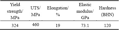
Figure 1 shows the process and part geometry employed for the present work. As shown, the strategy to produce cylindrical flanges was based on progressive increase of wall angle in four stages. The reason of choosing this strategy is that it can yield flanges with long necks [12].
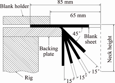
Fig. 1 Process and part geometry
Two types of elements, namely shell and solid, have been used for discretization of sheet blanks in SPIF. The use of solid elements costs significantly long computational time, while the shell element requires reasonably low time to complete the computational work. Moreover, the shell element yielded results in reasonable accuracy [19,20]. Therefore, discretization in the current work was done with shell element. The size of element also affects the computational time. To select an appropriate element size, sensitivity analysis was performed in which a cone of 45�� angle was formed by varying element size from 2 to 3.7 mm. The strain distribution in the FE model and real specimen was compared. Among various models, the FE model using element of size ��2.5 mm showed good agreement with the real one. Therefore, the sheet blank was discretized using the element of 2.5 mm in size. To prevent sliding of material during deformation, the boundary conditions were applied on the blank edges as given in Fig. 2.
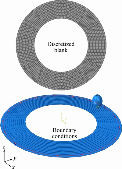
Fig. 2 Finite element model
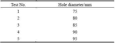
The forming tool was defined as a rigid translating body, and the material was defined as a deformable body obeying the following constitutive law: ��=149��0.2 derived from conducting standard tension tests on the material. The contact between the tool and sheet was defined as penalty and the friction coefficient between them was set to 0.05. To reduce analysis time, the mass scale of 16 was applied. The other parameters were as follows: tool diameter = 12 mm, step size=1 mm. The simulations of hole flanging were done using explicit dynamic approach by varying the hole size from 75 mm to 95 mm following the plan given in Table 2. The starting wall angle of the geometry was set to 45�� and was increased to 90�� in four stages as mentioned earlier. The forming in each stage was performed in a successive manner in which each small element of material was formed in multiple increments/contours.
Table 2 Test plan
Figures 3 and 4 present the von Mises stress history of two selected elements: one in the vicinity of blank holder and the other close to the edge of flange as indicated in the corresponding insets. There are four segments, each representing a stage, in each of the two shown history curves. Each segment consists of a peak followed by either a horizontal or an inclined curve. This follows that the deformation stress in each stage initially rises to a certain magnitude and subsequently settles down to lower value once the tool has fully evolved into the sheet.
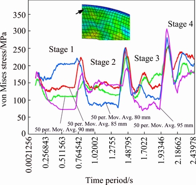
Fig. 3 Four stages stress history of element located in vicinity of blank holder

Fig. 4 Four stages stress history of element located in vicinity of flange edge
From Figs. 3 and 4, the peak stress required to initiate deformation in an element increases from Stage 1 to stage 4 because the deformation/wall angle correspondingly increases from 45�� to 90��. Comparing the first and last stages in the figures, it can be observed that the overall stress level rises with the increasing of stages which follows that the work hardening of material increases as the forming proceeds from the first stage to the last stage.
Comparing the influence of hole size on the forming stress, it is observed from the last stage in the two figures that the flanges with smaller holes (e.g., 80 and 85 mm) experience lower stresses than those with larger holes (e.g., 90 mm and 95 mm). Moreover, the element in the blank holder vicinity experiences less stress than the element nearby the flange edge does, e.g., peak stress of 250 MPa vs 300 MPa in a flange with pre-cut hole of 80 mm. It is noticed from Fig. 4 that the stress in the 3rd and 4th stages continuously falls after gaining a peak value (i.e., peak stress). This follows that the deformation of the element (nearby the flange edge and regardless of hole size) in the last two stages is not uniform comparative to their deformation in the earlier two stages. However, no such a behavior is observed in Fig. 3 which means that the sheet element near the clamped edge, regardless of the hole size, is deformed uniformly throughout the four stages.
Figure 5 presents the deformed meshes of four representative cylindrical flanges. As can be seen, the maximum stress in each sample is experienced by the element lying in the surrounding of flange/neck edge, which follows that the fracture is probable to take place in the vicinity of edge. A correlation between the hole size and the maximum stress experienced by the cylindrical flange is depicted in Fig. 6. As obviously, the maximum stress in general reduces as the hole size increases. It is worth noticing from Fig. 6 that amongst all samples, the maximum stress is encountered by a flange having a pre-cut hole of 75 mm, which approximates to 452 MPa and is very close to the tensile stress (460 MPa) of the material. This high stress indicates likelihood of sheet failure during real forming.
Figure 7 portrays the distribution of in-plane strains on a representative cylindrical flange. It is observed that the maximum straining occurs nearby the flange edge. Moreover, in agreement with the interesting experimental finding reported in Ref. [14], deformation besides longitudinal strains also takes place due to hoop strains despite the size of blank was kept large to prevent tool/sheet contact in the hoop direction. In fact, the free material around the pre-cut hole bends around the tool during forming thus in turn increasing the tool/sheet contact in the hoop direction and hence causing the development of hoop strains. As shown schematically in Fig. 8, the hoop contact reduces with the increasing of hole size. As a result, the hoop strains also decrease as depicted in Fig. 9. This points out that the development of hoop strains could affect the thickness distribution in the flange wall.
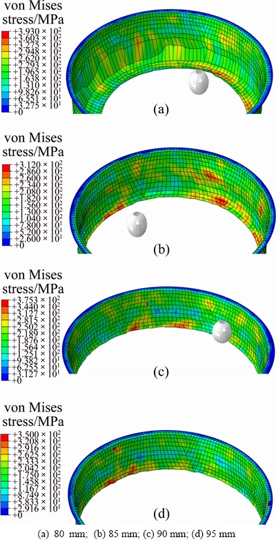
Fig. 5 Deformed meshes of cylindrical flanges
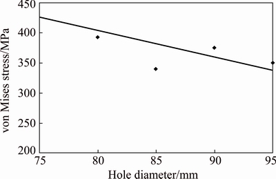
Fig. 6 Correlation between hole diameter and maximum von Mises stress experienced by sample
3 Experimental
The commercial aluminum, as used in the FE investigations, was employed as the experimental material. The thickness of the sheet was 1 mm and was cut to blanks of 170 mm2. The holes, ranging from 75 mm to 95 mm, were milled in the blanks and smoothened with the sand paper. The blanks were held in a clamping rig and were formed to cylindrical flanges in four stages starting from 45�� to 90�� utilizing a 3-axis computer numerically controlled (CNC) milling machine, and the following parameters: step size=1 mm; feed=70 mm/min; tool diameter=12 mm. The tool path to control the tool motions was generated using CAD/CAM software Power-Mill. To provide statistical means to the results, each experiment was repeated twice.
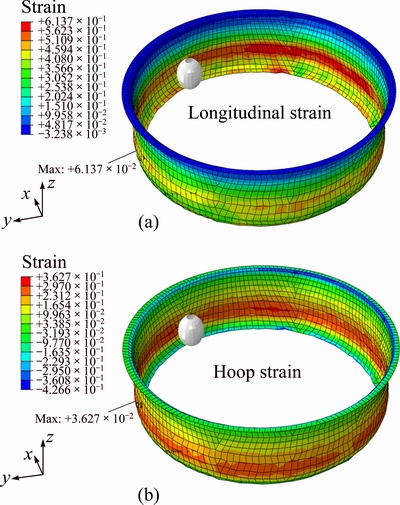
Fig. 7 Distribution of longitudinal (a) and hoop (b) strains in representative cylindrical flange (hole diameter = 85 mm)
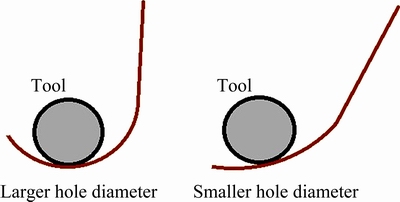
Fig. 8 Schematic diagram of tool/sheet contacting with changing hole size
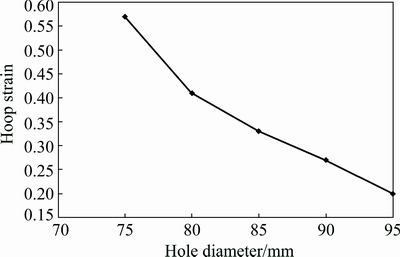
Fig. 9 Correlation between hole diameter and maximum von Mises stress experienced by sample
After forming, the samples were cut using a wire cut machine and their wall thickness was measured with a dial gauge indicator in an accuracy of ��0.005 mm. The height of the samples was measured with a depth gauge in an accuracy of ��0.01 mm. In this study, the height of cylindrical flange prior to sheet fracture was defined as the formability of hole flanging in SPIF.
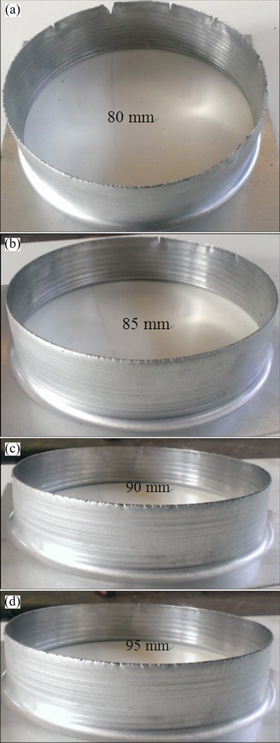
Fig. 10 Flanges formed with various holes
Figure 10 presents a set of representative cylindrical flanges. As can be seen, there are minor cracks around the flange/neck edge. This is in accordance with the FE finding mentioned before that an edge experiencing the highest stress is the most vulnerable region to fracture in the entire neck/flange. This is to see from samples that the cracks in agreement with the experimental finding reported in Ref. [13] are directed in the longitudinal direction, which follows that the cracks occurred due to longitudinal stresses.
The wall thickness profiles of flanges/necks are shown in Fig. 11. In each sample, there is the thinnest segment followed by a thicker one. The thinnest segment is due to deformation by hoops strain discussed above and shown in Figs. 7 and 9. The latter thick segment is due to the flow of material towards the edge of neck/flange. Regarding the influence of hole size, the thickness increases as the hole diameter increases, which can be attributed to corresponding reduction in the hoop strains mentioned earlier.
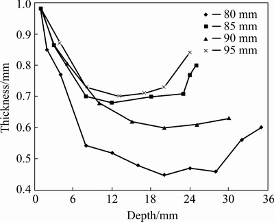
Fig. 11 Wall thickness profiles of flanges with various holes
Figure 12 exhibits the formability (i.e., flange/neck height) as a function of hole size. The formability increases from around 4 mm to 35 mm as the hole size increases from 75 mm to 80 mm and afterwards starts to gradually fall from 35 mm to 25 mm with the increase of hole size from 80 mm to 95 mm. Thus, 80 mm represents the threshold size of hole that offers the maximum formability of the experimental sheet. In fact, as expected above in the FE analysis, the sample with the hole diameter of 75 mm was observed to fracture in the beginning of the 4th stage and could not be successfully formed into a cylindrical flange. This endorses a previous finding [17] that a hole does not positively affect the formability if plastic deformation does not extend to its edge. In other words, excessive material under the tool leads to non-conducive condition. This points out that the formability decreases with the increase of hole size after 80 mm in spite of reduction in the von Mises stress and hoop strain (Figs. 6 and 9). This means that the material under the tool was not sufficient to be stretched to longer necks. From these findings, it follows that both of the massive and minute volumes of material under the forming tool do not constitute conducive conditions necessary to maximize the formability of incremental hole flanging.
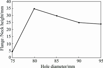
Fig. 12 Influence of hole diameter on formability in hole flanging
Comparing the von Mises stress experienced by various samples and the formability (Figs. 6 and 12), specifically the samples with pre-cut hole of 75, 80 and 85 mm, it is possible to conclude that a slight hardening improves the formability because it strengthens material to withstand forming load.
Summarizing the FE and experimental findings, the size of pre-cut hole plays an important role in determining the formability of cylindrical flanging in SPIF. The hole size does affect both the stress and strain distributions that in turn influence the wall thickness and fracture. Furthermore, there is a threshold size of hole that maximizes the formability. This is about 80 mm for the current AA1060 aluminum sheet metal. This value may change with a variation in the material and operating parameters. Further investigations are required to probe this point, therefore.
4 Conclusions
1) The stress required to deform an element is greater in the starting contours of a forming stage than that required in the rest of the contours. Further, the flange fractures, if it does, in the vicinity of its edge because the material in this region experiences the highest stress.
2) The hoop strains nearby the flange edge develop due to increased tool/sheet contact because of bending of material around the tool. The magnitude of these strains decreases as the hole size increases. As a result, the wall thickness of flange increases.
3) The maximum stress experienced by the flange decreases as the hole size increases from 75 mm to 95 mm. A blank with too small hole experiences severe stresses during forming leading to sheet fracture thus failing the successful forming of a cylindrical flange.
4) Too small or too large size of hole, both are not conducive for the formability in hole flanging. There is a threshold size of pre-cut hole that maximizes the formability (i.e., neck height). For the current material, this is realized when forming is performed using a blank having a pre-cut hole of 80 mm.
5) This study offers a new level of understanding in hole flanging by SPIF. Also, it lays down a basis following which threshold hole size for the other materials of interest and operative conditions can be determined.
References
[1] JESWIET J, MICARI F, HIRT G, BRAMELY A, DUFLOU J, ALLWOOD J. Asymmetric single point incremental forming of sheet metal [J]. Annals CIRP, 2005, 54: 623-650.
[2] LI J C, LI C, ZHOU T. Thickness distribution and mechanical property of sheet metalincrementalformingbased on numerical simulation [J]. Transactions of Nonferrous Metals Society of China, 2012, 22(S1): s54-s60.
[3] HAN F, MO J H, QI H, LONG R F, CUI X, LI Z W. Springback prediction for incremental sheet forming based on FEM-PSONN technology [J]. Transactions of Nonferrous Metals Society of China, 2013, 23(4): 1061-1071.
[4] DONG G J, ZHAO C C, CAO M Y. Flexible-die forming process with solid granule medium on sheet metal [J]. Transactions of Nonferrous Metals Society of China, 2013, 23(9): 2666-2677.
[5] JI Y H, PARK J J. Incrementalformingof free surface with magnesium alloy AZ31 sheet at warm temperatures [J]. Transactions of Nonferrous Metals Society of China, 2008, 18(S): s165-s169.
[6] OLEKSIL V, PASCU V, DEAC C, FLEACA R, BOLOGA O, RACZ G. Experimental study on the surface quality of the medical implants obtained by single point incremental forming [J]. International Journal of Materials Forming, 2010, 3: 935-938.
[7] LU B, OU H, SHI S.Q, LONG H, CHEN J. Titanium based cranial reconstruction using incremental sheet forming [J]. International Journal of Materials Forming, 2016, 9(3): 361-370.
[8] VERBERT J, BELKASSEM B, HENARD C, HABRAKEN A M, GU J, SOL H, LAUWERS B, DUFLOU J R. Multi-step tool path approach to overcome forming limitations in single point incremental forming [J]. International Journal of Materials Forming, 2008, 1: 1203-1206.
[9] FAN G, GAO L, HUSSAIN G, WU Z. Electric hot incremental forming: A novel technique [J]. International Journal of Machine Tools & Manufacture, 2008, 48(15): 1688-1692.
[10] KHALATBARI H, IQBAL A, SHI X, GAO L, HUSSAIN G, HASHEMIPOUR M. High-speed incremental forming process: A trade-off between formability and time efficiency [J]. Materials & Manufacturing Processes, 2015, 30: 1354-1363.
[11] SONG W Q, XU W J, WANG X U, MENG J B, LI H Y. Numerical simulation of temperature field in plasma-arc flexible forming of laminated-composite metal sheets [J]. Transactions of Nonferrous Metals Society of China, 2009, 19(1): s61-s67.
[12] CUI Z, GAO L. Studies on hole-flanging process using multistage incremental forming [J]. CIRP Journal of Manufacturing Science and Technology, 2010(2): 124-128.
[13] PETEK A, KUNZMAN A, FIJAVZ R. Backward drawing of necks using incremental approach [J]. Key Engineering Materials, 2011, 473: 105-112.
[14] GENTENO G, SILVA M B, CRISTINO V A M, VALLELLANO C, MARTINS P A F. Hole flanging by incremental sheet forming [J]. International Journal of Machine Tools & Manufacture, 2012, 59: 46-54.
[15] SILVA M B, TEIXEIRA P, REIS A, MARTINS. On the formability of hole-flanging by incremental sheet forming [J]. Proceeding of IMechE, Part L: Journal of Materials: Designs and Applications, 2013, 227: 91-99.
[16] MONTANARI L, CRISTINO V A, SILVA M B, MARTINS P A F. On the relative performance of hole-flanging by incremental sheet forming and conventional press-working [J]. Proceedings of IMechE Part L: Journal of Materials: Design & Applications, 2014, 228: 312-322.
[17] CRISTINO V A M, MONTANARI L, SILVA M B, MARTINS P A F. Towards square hole-flanging produced by single point incremental forming [J]. Proceeding of IMechE, Part L: Journal of Materials: Design & Applications, DOI: 10.1177/1464420714524930.
[18] BAMBACH M, VOSWINCKEL H, HIRT G. A new process design for performing hole-flanging operations by incremental sheet forming [J]. Proceedia Engineering, 2014, 81: 2305-2310.
[19] BAMBACH M, HIRT G. Performance assessment of element formulations and constitutive laws for the simulation of incremental sheet forming (ISF) [C]//Proceedings of the 8th Complas Conference. Barcelona: CIMNE, 2005.
[20] MACKERLE J. Finite element analyses and simulations of sheet metal forming processes [J]. Engineering Computation 2004, 21: 891-940.
��������Բ�����ߵ�����Ԫ��ʵ�����
G. HUSSAIN1, H. VALAEI2, Khalid A. Al-GHAMDI3, B. KHAN4
1. Faculty of Mechanical Engineering, GIK Institute of Engineering Sciences & Technology, KP 23640, Pakistan;
2. Mechanical Engineering Department, Eastern Mediterranean University, North Cyprus 99450, Turkey;
3. Department of Industrial Engineering, King Abdulaziz University, Jedda 80200, Saudi Arabia;
4. Dipartimento di maccanica, Polytecnico diMilnao, Italy
ժ Ҫ���о����㽥������������Ԥ�п׳ߴ��Բ�����ߵĿɳ����Ե�Ӱ�졣���������45�� �� 90���Ϊ4���Σ���������Ϊʵ����ϡ��׳ߴ��Բ�����ߵ�Ӧ��/Ӧ��ֲ�������Ӱ�졣���ſ׳ߴ����������Ӧ�������ߵıں�����ͬ���أ����ſ׳ߴ������von MisesӦ�����͡����ң��׳ߴ����һ���ٽ�ֵ(80 mm)�����������ֵʱ��������ص�Ӧ�����Ӷ����°�Ķ��ѣ�Բ�����߳���ʧ�ܡ����ſ׳ߴ�ļ�С���Ҵ����ٽ�ߴ�ʱ���ɳ����Խ��͡�������������ٽ�ߴ�Ϊ80 mm��ʹ�����ڽ����׳����еĿɳ����������
�ؼ��ʣ����ߣ����㽥�����Σ��ɳ����ԣ�Ӧ����Ӧ�䣻�ٽ�ֵ
(Edited by Xiang-qun LI)
Corresponding author: G. HUSSAIN; E-mail: gh_ghumman@hotmail.com; ghulam.hussain@giki.edu.pk
DOI: 10.1016/S1003-6326(16)64362-5
Abstract: The influence of the size of pre-cut hole of blank on the formability of cylindrical hole flanging in single point incremental forming (SPIF) was studied. The flange is produced in four stages starting from 45�� to 90�� and employing aluminum as the test material. It is shown that the hole size has significant effects on the stress/strain distribution on the cylindrical flange. The magnitude of hoop strains increases and the flange thickness increases as the hole size increases. Likewise, the von Mises stress reduces with the increasing of hole size. Further, there is a threshold value of hole size (i.e., 80 mm) below which severe stresses occur, which lead to sheet fracturing thus failing the successful forming of cylindrical flange. Moreover, the formability reduces as the hole size is increased above the threshold size. Finally, it is concluded that 80 mm is the threshold size of hole for maximizing the formability of aluminum sheet in incremental hole flanging.
