
J. Cent. South Univ. (2012) 19: 953-961
DOI: 10.1007/s11771-012-1097-z![]()
Numerical assessment on improving multistage centrifugal impeller performance by changing inlet skew angle at impeller inlet
M. N. Labib1, Woo Ju-sik1, Choi Du-youl2, T. Utomo3, B. Fajar3, Chung Han-shik4, Jeong Hyo-min4
1. Graduate School of Department of Mechanical and Precision Engineering, Gyeongsang National University,Tongyeong 650-160, Korea;
2. Fluid and Thermal Engineering Co. Ltd., Kyungnam 621-843, Korea;
3. Department of Mechanical Engineering, Engineering Faculty, University of Diponegoro, Semarang 1269, Indonesia;
4. Department of Mechanical and Precision Engineering, Gyeongsang National University,The Institute of Marine Industry, Tongyeong 650-160, Korea
? Central South University Press and Springer-Verlag Berlin Heidelberg 2012
Abstract:
Multistage centrifugal impellers with four different skew angles were investigated by using computational fluid dynamics. The purpose of this work is to investigate the influences of lean angle at the blade tip of the impeller inlet. Four variations of lean angles, that is, 8��, 10��, 15�� and 20��, were made at first stage impeller. Reynolds Average Navier Stokes equation was used in simulation together with a shear-stress transport (SST) k-w turbulence model and mixing-plane approach, respectively. Three dimensional fluid flows were simplified using periodic model to reduce the computational cost and time required. A good performance was expected that the secondary flow can be effectively reduced in the flow passage of the impeller without excessive increase in manufacturing cost caused by the secondary flow. The results show that secondary flow affects the main flow intricately to form vortices or having non-uniform velocity in the flow passage, which in turn results in substantial fluid energy loss not only in the impeller but also in the guide vane downstream of impeller. The numerical solutions were performed and allowed the optimum design and operating conditions to be obtained.
Key words:
1 Introduction
In recent year, research on turbomachinery was especially aimed at improving reliability performance and compactness, while at the same time reducing operational cost as the main purpose. The flow in a centrifugal compressor is very complicated, with strong three-dimensional features. The subject of designing impellers is mentioned in Refs. [1-4]. There have been continuous efforts to improve the performance of turbomachinery. Since the impeller is an active part of turbomachinery which adds energy to the fluid, its geometry plays a major role in the performance of centrifugal compressor. Performance improvements have been reported by introducing splitter blades [5-6], tandem blades [7], three-dimensional impeller design [8-9]. A detailed study by ELDER and GILL [10] showed that parameters, like slope of pressure rise characteristic, inducer incidence, impeller back sweep angle, number of impeller and diffuser vanes, and diffusion rate in rotor and stator, have significant effect on stability limit. HILDEBRANDT [11] investigated the effect of different backsweep angles and exducer width on the steady state impeller outlet flow pattern of centrifugal compressor with vaneless diffuser through computational fluid dynamics (CFD) simulations. It is shown that the impeller with increased backsweep provides more uniform flow pattern with better potential for diffusion process inside the diffuser. Many ways, such as laser based measurement (Doppler global velocimetry) and particle image velocimetry (PIV), have been taken to analyze the complexity of fluid structure turbomachinery. The ?ow through the centrifugal compressor is complex due to the growth of boundary layers and ?ow separation on blade surfaces, the formation of secondary ?ows due to rotation and passage curvature in the impeller region.
The secondary flow formation is associated with high losses and affects the operating range not only in the rotating impeller but also in the diffuser or guide vane downstream of the impeller. The total energy loss caused by the secondary flows is referred to as secondary flow loss. It is known that the low energy fluid in the boundary layers accumulated at a certain region in the flow passage because the secondary flows cause a flow separation in a large scale, thus producing positively sloped characteristic curve and preventing the stable operation of the turbomachinery. A discussion about the influence of internal diffusion on impeller efficiency was carried out by DEAN [12]. The result showed a trend of increasing efficiency with increased overall diffusion ratio. Overall diffusion ratio is defined as the ratio of impeller inlet relative velocity usually taken at the shroud to impeller discharge relative velocity (w1/w2).
In the context of three-dimensional (3D) impeller design, the blade skew means introduction of the variation in the blade angle from hub to shroud at the leading edge (inlet skew angle/lean) and at the trailing angle (exit skew angle). Blade skew is considered to redistribute the flow and move the high loss fluid from the suction side to the hub, resulting in significant reduction of the blade to blade flow variation at the impeller exit. Work reported by MOORE et al [13] showed the improvement in the compressor performance by introducing skew/lean to the impeller blades. Similarly, MOORE et al [14] have also shown the use of impeller blade skew to improve the uniformity of the exit flow. A patent by HARADA and SHIN [15] disclosed the blade skewing technique to improve the performance of the centrifugal compressors. It is claimed that the secondary flows can be suppressed by reducing the pressure gradient across the hub and the shroud by introducing the skew in impeller.
In this work, four designs at first impeller blade have been attempted. Four designs of impeller blade were made in different skew angle (lean angle) of the blade tip at the impeller inlet, deswirl vane, and second impeller, respectively, keeping all of the other parameters constant. This does not necessarily lead to optimal design but illustrates the effects of the different lean angle. The purpose of this work is to investigate the feasibility of the performance improvement of multistage centrifugal compressor with respect to minimum changes only in the impeller blade angle. The multistage centrifugal compressor was investigated numerically by using the CFD method. The CFD analyses were done using commercial CFD code CFX which solves the Reynolds Average Navier Stokes (RANS) equation numerically. The k-�� turbulence model was employed and a steady simulation was assumed. Calculated regions included a first impeller, deswirl vane and second impeller, respectively.
2 Numerical analysis
2.1 Assumptions
Steady state conditions were simulated and steam was assumed to be a real gas for all of the simulations. Because the current work is only focused on steady state simulations of the flow field, the results are considered valid only if the simulations are converged.
2.2 Grid system of model
The compressor was modeled as 3D periodic model in a commercial CFD software package (CFX 12). Three sections were used for the multistage centrifugal compressor simulation. To reduce the computational cost, only single passage on each stage was considered as a part of the computational domain. The simulation was modeled as a steady state problem using mixing plane (stage) interface. In the mixing plane (MP) approach, each fluid zone is treated as a steady state problem. Flow field data from adjacent zones are passed as boundary condition that are spatially averaged or ��mixed�� at the mixing plane interface. This mixing plane approach removes any unsteadiness that would arise due to the circumferential variations in the passage to passage flow field, thus yielding a steady state result.
The grid structure was hexahedral structured, as shown in Fig. 1. The grid density was concentrated at the critical areas where the significant phenomena were expected. The inlet boundary condition was defined as a subsonic inlet, and the temperature and mass flow rate were known. The turbulence intensity was defined to be about 5%. Periodic boundary conditions were applied to the impeller periodic plane at the middle of the impeller passage.
2.3 Construction of inlet skewed of impeller
The blade lean angle was defined as an angle between the blade center line and surface perpendicular to the hub surface on the cross-section of the flow passage in the impeller. According to the experiment results that have been conducted by HARADA and SHIN [15], it was considered as a maximum of the blade lean angle, the stress becomes larger as the lean angle is larger. They assumed that the allowable stress was to be 110% of the stress developed at the lean angle of 0��, and the limitation of the lean angle was 25��. As described above and with those reasons, this compressor was modeled with four different inlet skew (lean) angles of 8��, 10��, 15�� and 20��, respectively. Figure 2 shows the impeller with skew angles as mentioned before along with the baseline impeller. In this work, the skew was limited to a fraction of the impeller length near the leading edge and was only carried out at the first impeller in this multistage centrifugal compressor.
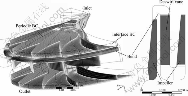
Fig. 1 Grid computational model
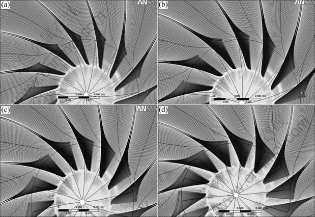
Fig. 2 Variations of blade lean angles of impeller inlet at first impeller: (a) 8��; (b) 10��; (c) 15��; (d) 20��
2.4 Grid sensitivity
To ascertain the CFD result further, a coarse grid sensitivity study was performed. This was done by calculating the multistage centrifugal compressor with six different grids, which differed from each other with cells number and y+ on every impeller as well as deswirl vane. All six cases and their respective cell numbers are given in Table 1. All grid sensitivity calculations are performed with the k-�� SST turbulence model.
In Fig. 3, it is shown that the grid variations are not significantly different in total to total isentropic efficiency, total to total pressure ratio, and total to total temperature ratio from the grid type number of three to grid type number of one. By the result of grid sensitivity variations, the further computation used the grid type number of three to optimize the time required and accurate result as a consideration. The design parameters were listed in Table 2.
Table 1 Cases and their respective number in grid sensitivity study
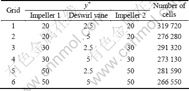
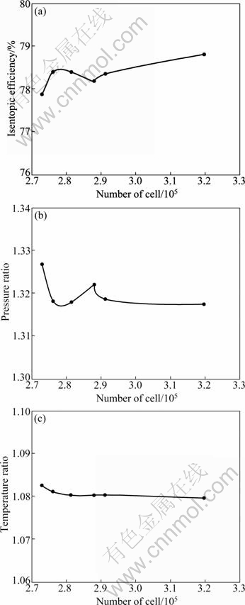
Fig. 3 Total-to-total isentropic efficiency (a), pressure ratio (b) and temperature ratio (c) as function of number of cells
2.5 Governing equation
The 3D Reynolds averaged compressible Navier Stokes equations together with an SST k-�� turbulence model were solved using a commercial CFD package (CFX 12). The mass and momentum conservation equations are given as
![]() (1)
(1)
![]()
![]() (2)
(2)
where �� represents the density (kg/m3), u is the velocity (m/s), p is the pressure (Pa), k is the turbulence kinetic energy (m2/s2), �� is the laminar viscosity (kg/(m��s)), and ��t is the turbulence viscosity (kg/(m��s)). The subscripts i, j and l represent the directions in x, y and z, respectively. Parameter ��ij is the kronecker delta, and it is equal to one when i=j; otherwise it is zero [16].
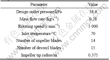
Table 2 Main design parameters of studied centrifugal compressor
The shear-stress transport model is a non-algebraic two-equation turbulence model suggested by Menter as a combination of the k-�� model and k-�� model. To take advantage of both, Menter applied the Wilcox k-�� model in the near wall region and gradually changed it into the standard k-�� model in the outer wake region. This model is considered as one of the best two-equation RANS models and is particularly suitable for a flow separation scenario such as cavity flow [17]:
![]()
![]() (3)
(3)
![]()
![]() (4)
(4)
![]() The turbulent shear stress is defined based on Bradshaw��s assumption that the shear stress is proportional to the turbulent kinetic energy, k, in the boundary layer,
The turbulent shear stress is defined based on Bradshaw��s assumption that the shear stress is proportional to the turbulent kinetic energy, k, in the boundary layer, ![]() where a1 is a constant. The eddy-viscosity is given by vt=a1k/max(a1��, ��F1), in which �� is the absolute value of the vortices and F1 is
where a1 is a constant. The eddy-viscosity is given by vt=a1k/max(a1��, ��F1), in which �� is the absolute value of the vortices and F1 is
given by ![]() The energy conservation equation is
The energy conservation equation is
![]() (5)
(5)
where E is the total energy (m2/s2), and the thermal conductivity k (W/(m��K)) is based on the kinetic theory:
![]() (6)
(6)
where k is thermal conductivity of steam (W/(m��K)), cp is the specific heat capacity of steam (J/(kg��K)), and Mw is the molecular mass.
3 Result and discussion
All compressor characteristics of the developed impellers were compared with those of the lean angles as a parameter. From Figs. 4 and 5, it is shown that altering the lean angle at blade inlet leads to increase in the pressure ratio as well as the efficiency of the compressor. Clearly, increasing of pressure ratio can improve the stage of efficiency of compressor. It could be seen that the maximum pressure rise is developed at 20�� of inlet skew angle. Figure 5 shows impeller efficiency (not stage) characteristic curves obtained by CFD. From this result, it is concluded that increasing the lean angle at impeller inlet contributes to raise the impeller efficiency and obviously would increase the stage efficiency as well.
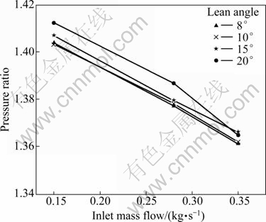
Fig. 4 Performance of compressor influenced by different lean angles at impeller inlet
In this work, the outlet pressure of every model was set at 38.6 kPa, and inlet mass flow rate was applied under inlet boundary condition by mean to compare the performance of compressor from suction inlet as a comparison parameter. As a computation finishes, it is found that inlet pressure of every variation of inlet skew angle has different magnitudes. This means that the suction pressure at inlet would be different depending on the lean angle at impeller inlet. Lower suction pressure at inlet means higher performance as well as higher pressure ratio.
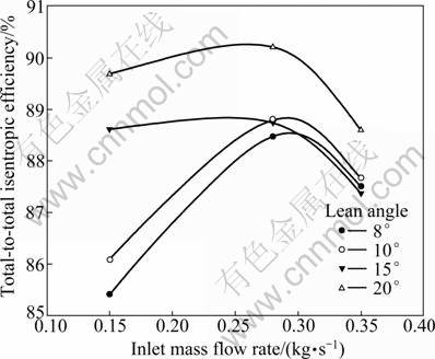
Fig. 5 Impeller performance characteristic curves
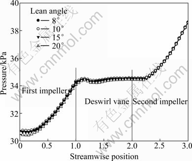
Fig. 6 Pressure distribution along streamwise
The relative velocity distribution along the streamwise is not different significantly. The calculated results for relative velocity from inlet to outlet is shown in Fig. 7. The difference of diffusion ratios are not significantly different. The diffusion ratios of 2.022, 2.049, 2.051 and 2.147 for lean angle of 8��, 10��, 15�� and 20�� are obtained, respectively. Lean angle influences the secondary flow because of flow separation occurring in deswirl vane. Lean angle of 20�� produces higher velocity distribution in deswirl vane and the highest diffusion ratio among of all variations.
The significant influences of changing the impeller lean angle at inlet on turbulence viscosity are shown in Fig. 8. As we know, the turbulent transfer of momentum by eddy gives rise to an internal fluid friction. This value represents the phenomena of vortex inside the compressor. Figure 8 shows that large eddy viscosity occurs in the deswirl vane. And the largest eddy viscosity is created at 20�� of lean angle. It is reasonable that, when the pressure ratio is high, the eddy obviously happens because of restriction flow was estricted.
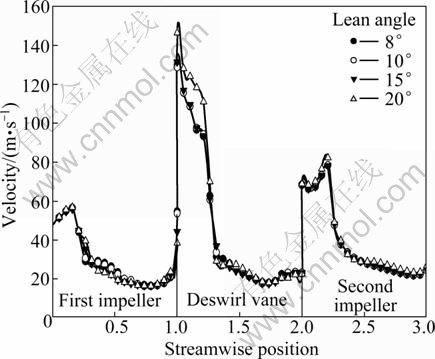
Fig. 7 Relative velocity distribution along streamwise
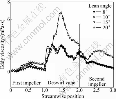
Fig. 8 Eddy viscosity distribution along streamwise
Figure 9 shows that by increasing the lean angle at impeller inlet, flow pattern is led to be more stable. The flow vector is shown in Fig. 9. It seems that flow pattern is to be smoother in 85% of the distance from hub to shroud by increasing the lean angle. It is reasonable that secondary flow can be minimized by increasing the lean angle. The higher lean angle in this case can make delaying or longer distance for fluid flow that will be separated from wall surface in the wall.
Figure 10 shows the shaft power on the blade that is transferred from steam as working fluid to every blade. We can see that at the same inlet mass flow rate, the absorbing of momentum energy by those blades is not different significantly at the same rotational speed in every variation of inlet skew angle. These curves illustrate the fact that at a fixed speed, the impeller inlet skew angle determines the load placed on the shaft at any given flow rate and thus the power that the motor will draw from the service at that flow rate. And with the same input power the efficiency and performance that can be created are different in different inlet skew angles.
Quantitative comparisons of different inlet skew angles of the reduced static pressure distribution on the blade surface are presented in Fig. 11, for the mass flow rate of 0.15 kg/s. The reduced static pressure (Pr) distribution on the blade surfaces at all measured spanwise sections from 5% to 98% is shown. The reduced static pressure distribution in the blade surface along the leading edge to the trailing edge at every variation of inlet skew has different magnitudes and has a distribution in all variations in which the pressures are high at the hub side and low at the shroud side. So pressure gradient balances the centrifugal force and coriolis force which are directed toward the hub side. In the boundary layer along the blade surface, since the relative velocity is reduced by the influence of the wall surface, the centrifugal force and the coriolis force which act on the fluid in the boundary layer become small. Figure 11 shows that the 20�� of inlet skew angle has the highest reduced static pressure distribution from leading edge to the middle of the streamwise based on the blade aligned. Also, the distribution of pressure gradually decreases from hub to shroud. It is clearly shown that the total pressure distributions decrease by increasing the percentage of spanwise distance.
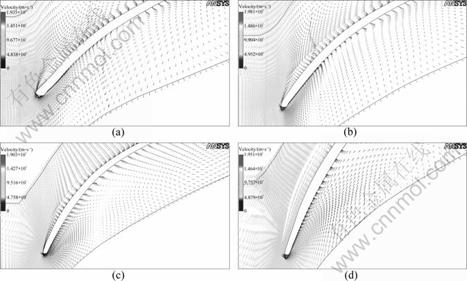
Fig. 9 Velocity vector of different lean angles at impeller inlet on 85% from hub to shroud: (a) 8��; (b) 10��; (c) 15��; (d) 20��
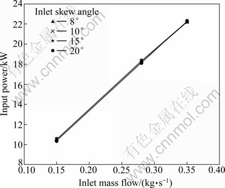
Fig. 10 Mass flow rate vs input power consumption
The comparison between the variations of inlet skew angle is performed in Fig. 12 in order to bring out the effect of the inlet skew angle at the inlet impeller on the compressor performance. These contours of eddy viscosity show the effect of inlet skew angle at impeller inlet. It could be seen clearly that larger eddies occur at the smaller inlet skew angle. In the range of the attempted models, 8�� and 10�� of inlet skew angle have an eddy in the leading edge of blade at the pressure side and by increasing the inlet skew angle to 15�� and 20��, the eddies in the pressure side of leading edge can not be seen anymore. By this contour of eddy viscosity, it is clearly concluded that increasing the inlet skew angle at inlet tends to decrease the separation flow in the leading edge of the blade. It has been proven that higher inlet skew angle is able to delay or make longer duration of flow separated. And it must be taken into account that in many cases of turbomachinery the surge takes place when the incidence angle is changed and the flow separation occurs.
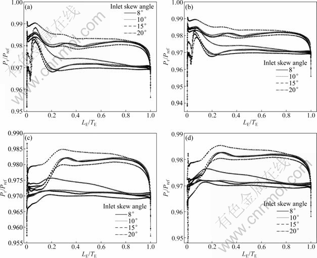
Fig. 11 Comparison of reduced static pressure distributions at spanwise sections: (a) 5% span; (b) 15% span; (c) 85% span; (d) 98% span (Pr means that reduced static pressure, Pref means the reference pressure; LE/TE means the normalized length of the impeller blade from leading edge to trailing edge.)
According to Fig. 13, the contour of Mach number shows that the smaller inlet skew angle has smaller Mach number in the region near the shroud area. The dark color in Fig. 13 indicates clearly that 8�� of inlet skew angle has the smallest Mach number near the shroud. It can be seen that low velocity region near the shroud can be minimized as the lean angle increases. Increasing the inlet skew angle tends to make the flow pattern become more uniform, which means that the flow velocity triangle is more favorable at the inlet.
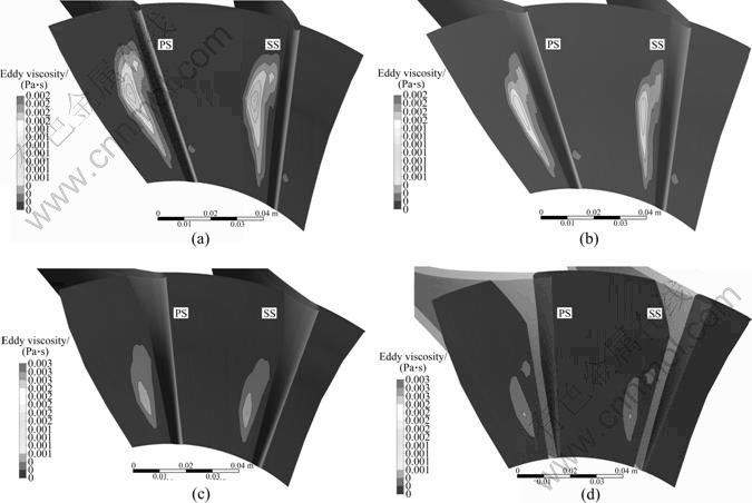
Fig. 12 Contour of eddy viscosity at different skew angles of impeller inlet: (a) 8��; (b) 10��; (c) 15��; (d) 20��
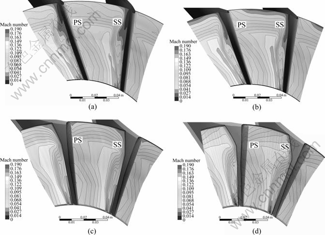
Fig. 13 Contour of Mach number at different skew angles of impeller inlet: (a) 8��; (b) 10��; (c) 15��; (d) 20��
4 Conclusions
1) The influences of the lean angles at impeller inlet are numerically investigated in this work. Evidently, increasing lean angle in impeller inlet leads to increase in the pressure ratio of compressor.
2) It is shown that the higher pressure ratio is created at higher impeller lean angle at inlet. The results show that the highest performance is achieved at 20�� of lean angle.
Nomenclature
k
Turbulent kinetic energy, thermal conductivity
LE
Leading edge
N
Rotational speed, r/min
p
Static pressure, Pa
Pr
Reduced static pressure, Pa
Pref
Reference pressure, Pa
PS
Pressure surface
u
Tangential velocity at impeller, m/s
vt
Kinematic eddy viscosity, kg/(m��s)
w
Relative velocity, m/s
y+
Non-dimensional distance from wall
Z
Number of blades
SS
Suction surface
TE
Trailing edge
��
Dissipation rate, m2/s3
��
Fluid density, kg/m3
��
Absolute value of vortices
��
Laminar viscosity, kg/(m��s)
��t
Turbulent eddy viscosity, kg/(m��s)
��
Wall shear stress, kg/(m��s2)
��
Specific dissipation rate
References
[1] BALJE E. Turbomachines: A guide to design, selection and theory [M]. New York: JohnWiley & Sons, NY, USA, 1981.
[2] DIXON S L. Fluid mechanics, thermodynamics of turbomachinery (3rd Edition) [M]. Oxford, UK: Pergamon Press, 1989.
[3] JAPIKSE D. Centrifugal compressor design and performance [M]. Concepts ETI, Wilder, Vt, USA, 1996.
[4] SARAVANAMUTTOO H I H, ROGERS G F C, COHEN H. Gas turbine theory (5th Edition) [M]. Prentice-Hall, Upper Saddle River, NJ, USA, 2001.
[5] HIGASHIMORI H, HASAGAWA K, SUMIDA K, SUITA T. Detailed flow study of mach number 1.6 high transonic flow with a shock wave in pressure ratio 11 centrifugal impeller [J]. Trans ASME Journal of Turbomachinery, 2004, 126: 473-481.
[6] LAROSILIERE L M, SKOCH G J, PRAHST P S. Aerodynamic synthesis of centrifugal impeller using CFD and measurements [C]// 33rd Joint Propulsion Conference and Exhibit AIAA-97-2878. Technical Report ARL-TR-1461, 1997.
[7] ROBERT D A, KACKER S C. Numerical investigation of tandem impeller design for gas turbine compressor [J]. Trans Asme Journal of Turbomachinery, 1992, 124(1): 36-44.
[8] ZANGENEH M. On the 3D design method for radial and mixed flow turbomachinery blades [J]. Int Journal of Numerical Method In Fluids, 1991, 13: 559-624.
[9] ZANGENEH M. On 3D inverse design of centrifugal compressor impeller with splitter blades [C]// 43rd ASME International Gas Turbine and Aeroengine Congress and Exposition. Stockholm, Sweden, 1998.
[10] ELDER, GILL M E. A discussion on the factor affrecting surge in centrifugal compressor [J]. Trans ASME Journal of Engineering for Gas Turbine and Power, 1985, 107: 499.
[11] HILDEBRANDT A G. Numerical investigation of the effect of different backsweep angle and exducer width on the impeller outlet flow pattern of a centrifugal compressor with vaneless diffuser [J]. Trans Asme Journal of Turbomachinery, 2007, 129: 433.
[12] DEAN R. On the unresolved fluid dynamics of the centrifugal compressor [J]. Advanced Centrifugal Compressors, 1971: 1-55.
[13] MOORE J, MOORE J G. Use of blade lean in turbomachinery redesign, nasa marshall space flight center [C]// Eleventh Workshop of Computational Fluid Dynamic Applications in Rocket Propulsion. 1994.
[14] MOORE J, MOORE J G, TIMMIS P H. Performance evaluation of centrifugal compressor impeller using 3D viscous flow [J]. Trans ASME, Journal of Engineering for Gas Turbines and Power, 1984.
[15] HARADA H, SHIN K. Centrifugal turbomachinery [P]. US Patent 6 338 610.
[16] JIAO K, SUN H. Numerical simulation of air flow through turbocharger compressor with dual volute design [J]. Applied Energy Journal, 2009, 86(11): 2494-2506.
[17] ZHISONG L, HAMED A. Numerical simulation of sidewall effects on the acoustic field in transonic cavity [C]// Proceedings of 45th AIAA Aerospace Sciences Meeting. Nevada, USA, 2007.
(Edited by DENG L��-xiang)
Foundation item: Project(NRF-2010-013-D00007) supported by the National Research Foundation of Korea; Work finacially supported by the 2010 Research Professor Fund of Gyeongsang National University, Korea
Received date: 2011-04-21; Accepted date: 2011-07-04
Corresponding author: Jeong Hyo-min, Professor, PhD; Tel: +82-10-65483184; E-mail: hmjeong@gnu.ac.kr
Abstract: Multistage centrifugal impellers with four different skew angles were investigated by using computational fluid dynamics. The purpose of this work is to investigate the influences of lean angle at the blade tip of the impeller inlet. Four variations of lean angles, that is, 8��, 10��, 15�� and 20��, were made at first stage impeller. Reynolds Average Navier Stokes equation was used in simulation together with a shear-stress transport (SST) k-w turbulence model and mixing-plane approach, respectively. Three dimensional fluid flows were simplified using periodic model to reduce the computational cost and time required. A good performance was expected that the secondary flow can be effectively reduced in the flow passage of the impeller without excessive increase in manufacturing cost caused by the secondary flow. The results show that secondary flow affects the main flow intricately to form vortices or having non-uniform velocity in the flow passage, which in turn results in substantial fluid energy loss not only in the impeller but also in the guide vane downstream of impeller. The numerical solutions were performed and allowed the optimum design and operating conditions to be obtained.
