
J. Cent. South Univ. (2017) 24: 2829-2841
DOI: https://doi.org/10.1007/s11771-017-3698-z

Thermodynamic optimization and fluid selection of organic Rankine cycle driven by a latent heat source
XU Peng(����)1, LU Jian(����)1, LI Tai-lu(��̫»)1, ZHU Jia-ling(�����)2
1. School of Energy and Safety Engineering, Tianjin Chengjian University, Tianjin 300384, China;
2. Key Laboratory of Efficient Utilization of Low and Medium Grade Energy, Ministry of Education(Tianjin University), Tianjin 300072, China
 Central South University Press and Springer-Verlag GmbH Germany,part of Springer Nature 2017
Abstract:
Organic Rankine cycle (ORC) is applicable for the heat-work conversion. Whereas, there also exist a lot issues that influence the efficiency and the cost of the system. In this work, eleven pure working fluids (as categorized into alkanes, and fluorinated alkanes) are investigated based on the first and second law of thermodynamics. The major objective is to obtain the most suitable working fluid for the latent heat source. The results show that the working fluid is an important factor of the system performance. The heat absorption of the working fluid in the evaporator is inversely proportional to the evaporating temperature, but the thermal and exergetic efficiencies are just the opposite. RC318 has the highest net power output and the lowest outlet temperature of the heat source, but its global warming potential (GWP) value is too high. The cyclohexane shows the highest thermal efficiency among the fluids investigated. Moreover, the figure of merit (FOM) of the isobutane is higher than that of other working fluids. Overall, the cyclohexane shows that the optimal comprehensive performance is more feasible for medium grade heat source in engineering applications.
Key words:
organic Rankine cycle; working fluids; thermodynamics; low-temperature; evaporating temperature��
1 Introduction
Renewable energies have attracted much more attention as a result of the shortage of the global energy, such as solar energy [1], geothermal energy [2], the waste heat [3], ocean thermal energy [4], and wind energy. Among them, the heat-work conversion for low- and medium-temperature heat source is the most frequently studied. Especially, the organic Rankine cycle (ORC) has attracted much attention due to its simple cycle configuration, high reliability and flexibility, and convenient maintenance in the past few decades [5�C8]. Whereas, the thermal efficiency is low, only 8%�C12% [9], but the economic benefit is poor.
According to the research in recent years, in order to improve the utilization of the heat source, the optimization of the ORC system has been mostly focused on, such as the minimization of the system irreversibility loss and the choice of the working fluids. MAGO et al [10] did an analysis about the exergy destruction and obtained that the exergy destruction in evaporator is about 77%, much higher than other cycle configuration. ZHU et al [11] analyzed the plate heat exchangers (PHE) in evaporator and found that by optimizing its design, the PHEs will effectively be smaller than the real example given, with a consequent reduction in cost. CLEMENTE et al [12] investigated scroll expanders derived from the compressors in the heating, ventilation and air- conditioning (HVAC) field to recover heat from an internal combustion engine. WANG et al [13] proposed a novel system combining a dual loop ORC with a gasoline engine. LI et al [14] investigated the low temperature solar thermal electric generation with ORC. MAVROU et al [15] proposed a systematic sensitivity analysis procedure explicitly considering the impacts of working fluid and ORC design/operating decisions on the ability of the ORC to operate under conditions different from its nominal design settings to select working fluid mixtures in view of operating variability in solar organic ranking cycles (ORC). HE et al [16] proposed a combined ORC system utilizing exhaust waste as its heat source and liquid natural gas (LNG) as its heat sink to provide alternative power for an LNG- fired vehicle and examined five working fluids at various working conditions, and they found that R236fa has the highest thermal efficiency. WU et al [17] presented the performance of ORC using hot air as heat resource using zeotropic mixture fluids R227ea/R245fa, Butane/R245fa and RC318/R245fa as the working fluids. The result indicates that better thermal performance can be achieved when the temperature difference of cooling water is near the temperature glide of zeotropic mixture in the condenser. DESAI et al [18] did a thermo- economic analysis and selection of working fluid for solar ORC.
There are also some scholars focus on the components change of the ORC system for the power output and economy of the system, such as the regenerative organic Rankine cycle (RORC), the parallel double-evaporator organic Rankine cycle (PDORC), the two-stage series organic Rankine cycle (TSORC) and so on. MAGO et al [19], XI et al [20], PEI et al [21], FERN NDEZ et al [22], and ROY et al [23] analyzed RORC and found that the supercritical RORC is preferable for high temperatures heat source. The internal heat exchanger is the main factor to system efficiency. LI et al [24] proposed and compared PDORC with the ORC to show that the irreversible loss of the PDORC is lower than that of the ORC. BORSUKIEWICZ-GOZDUR et al [25] tried to increase the working fluid flow rate as a kind of method to enhance the power output of geothermal power plant. LI et al [26] constructed and experimentally analyzed the RORC and found that the thermal load of the condenser and the irreversible loss reduced at the same time. Moreover, the thermal efficiency of the RORC is higher than that of the ORC by 1.83%.
Besides the cycle parameters and the cycle configuration, the working fluid has an important influence on the system performance. BADR et al [27] investigated thermodynamic and thermophysical properties of organic working fluids. HUNG et al [28] used ammonia, benzene, R11, R12, R134a and R113 as the working fluid, respectively, and compared the efficiencies of ORCs with each working fluid. SALEH et al [29] gave a thermodynamic screening of 31 pure component working fluids for ORCs, the largest amount of heat can be transferred to a supercritical fluid and the least to a high-boiling subcritical fluid. Based on the first and second laws of the thermodynamics, YARI [30, 31] investigated several dry fluids for ORC, and DESAI et al [32] presented that the dry fluids were the better working fluid for ORC utilizing low-grade heat sources. Also, the wet fluids were investigated by HUNG et al [33], showing that the wet fluids with very steep saturated vapor curves in the T�Cs diagram for the refrigerant-series and benzene-series fluids had a higher overall performance in energy conversion efficiencies than that of dry fluids. LIU et al [34] presented that the thermal efficiency and the total heat recovery efficiency were different for various working fluids.
For the pure working fluids, their thermodynamic properties may be the issues in engineering applications, such as corrosive, toxic, flammable and environmental harmful. So the mixed working fluids are a way to solve the issues. For example, some hydrocarbons have a very good power performance, but flammable is a problem for hydrocarbons working fluids. Therefore, adding a certain proportion of the working fluid which has excellent performance and flame retardant, can realize safe and efficient application of the working fluids. PAPADOPOULOS et al [35] presented that the selection of the working fluids significantly limited the opportunities of identifying highly performing options. CHEN et al [36] indicated that zeotropic mixtures had a higher efficiency. LAKEW et al [37] found that the power output of the R227ea is highest for the heat source temperature range from 80 ��C to 160 ��C, and the R245fa gave the highest power output when the temperature ranges from 160 ��C to 200 ��C. PASETTI et al [38] presented an improved survey method for the evaluation of the thermal stability of working fluids for ORCs. LI et al [39] proposed a novel combined cooling, heating and power organic Rankine cycle (CCHP-ORC) system installed with heat pumps to select optimal zeotropic mixtures and determined the component concentration that gives a better performance.The results showed that R141b/R134a, R141b/R152a and R123/152a have a higher COP and exergy efficiency than others. MAVROU et al [40] investigated the performance of working fluid mixtures for use in solar ORC with heat storage employing flat plate collectors (FPC) and assessed the impact of heat source variability on the ORC performance for different working fluid mixtures, and a mixture of neopentane-2-fluoromethoxy-2- methylpropane at 70% neopentane was the most efficient in all the considered criteria simultaneously. Besides the mentioned above, many factors should be considered for the working fluid choice, such as specific volume, low viscosity, global warming potential (GWP), ozone depletion potential (ODP), high latent heat of vaporization, high thermal conductivity and a stable operating pressure. It should be pointed out that a large number of researchers have focused on the heat-work conversion for low- and medium-grade sensible heat, and few literatures have been found to discuss the working fluid selection of ORC driven by low- and medium-grade latent vapor resource resources.
In this work, the saturated vapor was adopted as the heat source, which has the latent and sensible heat at the same time, and eleven kinds of working fluids was chosen for comparison. Based on the first and second laws of thermodynamics, the parameters, such as power output, irreversible loss, total thermal conductance, exergetic efficiency, and thermal efficiency were optimized. The ORC with each working fluid was identified based on the cycle performance.
2 System descriptions
Figure 1 shows the system flow chart of the ORC, which can be categorized in three loop circuits according to the working media: the heat source, the working fluid, and the heat sink. As shown in Fig. 1, it can be got that the ORC is made of an evaporator, a turbine, a generator, a condenser, a pump, a hot water pump, a cooling water pump, and a cooling tower.
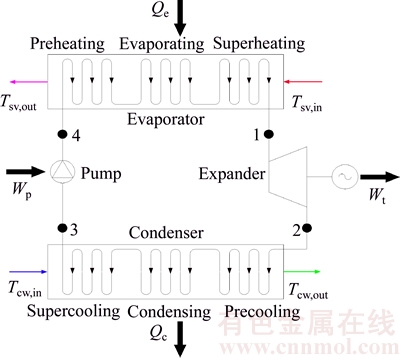
Fig. 1 Schematic diagram of an ORC system
The heat source is saturated vapor, which comes from metallurgical plant and steel mills. Compared with geothermal water, there is the latent heat of saturated vapor, which is far greater than the sensible heat under the condition of unit mass. When the saturated vapor releases heat and flows out of evaporator in the form of water, it can be used in other aspects.
The saturated vapor first flows into the evaporator to transfer heat to the working fluid to generate high-pressure vapor (Figs. 1 and 2, state 1), and it is released into the atmosphere. The working fluid absorbs the heat from the saturated vapor to generate high- pressure in the evaporator, then the vapor flows into the turbine and its enthalpy is converted into shaft work to drive the generator. The vapor existed from the turbine (Figs. 1 and 2, state 2) is led to the condenser where it is liquefied by cooling water. The liquid available at the condenser outlet (Figs. 1 and 2, state 3) is pressurized by the pump and flow into the evaporator (Figs. 1 and 2, state 4). The ORC can be identified as 1��2��3��4, shown by black lines. The cooling water goes into the condenser driven by the cooling water pump. Then a new cycle begins. The T�Cs diagram is shown in Fig. 2.
3 Modeling
Based on the first and second laws of thermodynamics, the energetic and exergetic analysis were carried out for the working fluid researched. For simplicity, the following hypotheses are made:
1) The saturated vapor is supplied in a steady-state condition, at a heat source of 130 ��C;
2) Superheated vapor is considered at the evaporator outlet, with a degree of superheat of 5 K. Supercooled liquid is considered at the condenser exit, with a degree of superheat of 5 K;
3) The kinetic and potential energy changes are negligible;
4) Pressure drops throughout the evaporator, the condenser and the pipelines are negligible;
5) The temperature and friction losses are negligible.
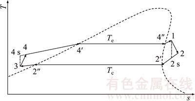
Fig. 2 T�Cs schematic diagram of an ORC system
The mathematical model for ORC is expressed by the following equations:
Turbine:
 (1)
(1)
where �� and h denote the efficiency and enthalpy, respectively; the subscripts t and s represent the turbine and isentropic process, respectively.
 (2)
(2)
 (3)
(3)
where W and mwf stand for the power output and the mass flow rate, respectively; the subscript wf means the working fluid.
 (4)
(4)
where I and s represent the irreversible loss and the entropy, respectively; T0 stands for the environment temperature.
Condenser:
Figure 3 shows the T�Cq diagram of the heat transfer process in the condenser. Clearly, as presented in Fig. 3, it can be seen that the processes of T2��T2����T2����T3 and Tcw,in��Tcw,1��Tcw,2��Tcw,out represent the temperature variations of the working fluid and the cooling water in the condenser, respectively. There are superheated vapor of the working fluid at the condenser inlet and super-cooled fluid at the condenser outlet. The process in condenser is composed of three parts: super-cooling, condensing and pre-cooling, which separately represented by I, II and III. Tcw,1 and Tcw,2 are the temperature of cooling water leaving and entering the condensing part.
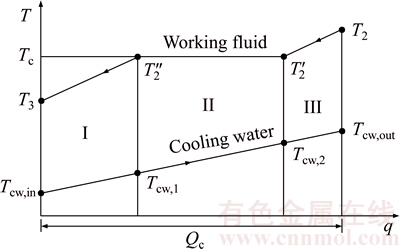
Fig. 3 T�Cq diagram for heat transfer in condenser
 (5)
(5)
 (6)
(6)
 (7)
(7)
 (8)
(8)
where Q denotes the thermal load; the subscripts c and I, II, III stand for the three sections of condenser shown in Fig. 3.
 (9)
(9)
 (10)
(10)
 (11)
(11)
 (12)
(12)
where (KA)c,I, (KA)c,II and (KA)c,III are the thermal conductance of sections I, II and III of condenser, respectively; K , A and ��T stand for the heat transfer coefficient, the heat transfer area, and the logarithm mean temperature difference, respectively.
 (13)
(13)
 (14)
(14)
 (15)
(15)
where Wp,cw means the power consumption of the cooling water pump, Pcw is the pressure loss in the cooling water circuit and ��cw represents the density for the cooling water; subscripts cw and p stand for the cooling water and the pump, respectively.
 (16)
(16)
 (17)
(17)
 (18)
(18)
where h4s is specific enthalpy at the pump outlet experiencing an isentropic process.
Figure 4 shows the temperature difference variation between saturated vapor and working fluid in the evaporator versus the heat transfer rate q, T�Cq diagram. From Fig. 4, it can be evidently seen that the processes of T4��T4����T4����T1 and Tsv,in��Tsv,1��Tsv,2��Tsv,out represent the temperature variations of the working fluid and the saturated vapor in the evaporator, respectively. There are superheated vapor of the working fluid at the condenser inlet and super-cooled fluid at the condenser outlet. With condenser, the evaporator also can be divided into three sections: preheating, evaporating and vapor superheating sections; which are represented by I, II and III. Tsv,1 and Tsv,2 represent the temperatures of saturated vapor leaving and entering the evaporating section.
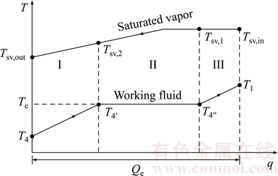
Fig. 4 T�Cq diagram for heat transfer in evaporator
 (19)
(19)
 (20)
(20)
 (21)
(21)
 (22)
(22)
where the subscripts 1 and 4 stand for the outlet and inlet of the working fluid at evaporator.
 (23)
(23)
 (24)
(24)
 (25)
(25)
 (26)
(26)
where (KA)e,I, (KA)e,II and (KA)e,III are the thermal conductance of Sections I, II and III of evaporator, respectively.
 (27)
(27)
 (28)
(28)
where Wp,sv, psv, ��p,sv and ��sv are the power consumption of saturated vapor pump, the pressure provided by the saturated vapor pump, the efficiency of the saturated vapor pump, and the density for the saturated vapor; the subscripts sv, in and out represent the saturated vapor, the inlet and outlet of the evaporator for saturated vapor, respectively.
Total irreversibility:


 (29)
(29)
The total thermal conductance of heat exchangers:
 (30)
(30)

 (31)
(31)
Net power output:
 (32)
(32)
where ��m and ��g are the mechanical efficiency and the efficiency of the generator.
The heat flow rate released to the environment Q0 is:
 (33)
(33)
where Csv and Ccw are the heat capacities of the saturated vapor and the cooling water, respectively.
The volumetric flow rate (VFR, Rvf) is given as:
 (34)
(34)
where v1 and v2 stand for the volumetric flow rate of the inlet and outlet at the turbine, respectively.
Thermal efficiency:
 (35)
(35)
The exergy for saturated vapor at inlet and outlet of the evaporator can be expressed as
 (36)
(36)
where hsv,in and hsv,out denote the enthalpy of the saturated vapor at the evaporator inlet and outlet.
 (37)
(37)
Exergetic efficiency:
 (38)
(38)
where EXsv is the exergy input into the cycle provided by saturated vapor.
4 Results and discussion
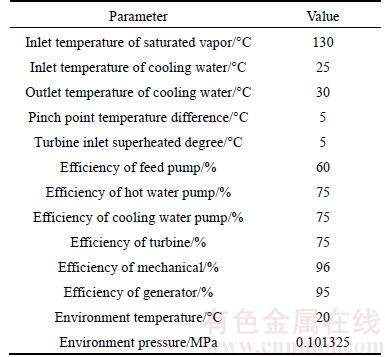
In this work, eleven kinds of pure working fluids were used in the subcritical ORC based saturated vapor as an example for low- and medium-grade heat source, and the main physical properties of the working fluids are shown in Table 2. Table 3 shows the system parameters and ambient conditions used in this work, which is obtained from an existed practical ORC system.
From Table 2, it can be seen that the GWP of working fluid RC318 is 10250, much bigger than other working fluids, which means RC318 has a stronger influence on greenhouse effect. Also the ALT of RC318 reaches the maximum value of all working fluid, which represents that it is a long time for RC318 to exist in the natural environment without being damaged or break down. Among the working fluids, the alkanes, including isobutane, isopentane, n-pentane, n-hexane, n-pentane, n-decane and cyclohexane, have the flammable characteristics. It should be known that the type changing of the turbine usually leads to the variation of expansion efficiency. To simplify the calculation, it is assumed that the isentropic efficiency of the turbine is unchanged. And the mass flow rate of saturated vapor is 1 kg/s.
Table 2 Thermodynamic properties of working fluids
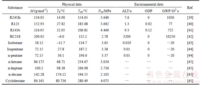
Table 3 Data used to simplify calculation in this work
4.1 Mass flow rate of working fluids
Figure 5 shows the variation of the mass flow rate of the different working fluids versus the evaporating temperature. It can be seen that the variation trends of mass flow rate of all working fluids are the same. A rise in evaporating temperature decreases the mass flow rate. Based on the law of energy conservation, the mass flow rate is directly inversely proportional to the enthalpy difference of the working fluid between the inlet and outlet of the evaporator with the heat and cold source remaining steady. And the increase of the evaporating temperature decreases the enthalpy of the evaporate outlet, therefore leading to a drop in the mass flow rate of the working fluids. The mass flow rate of RC318 ranges from 2.607 kg/s to 1.982 kg/s with the evaporating temperature change from 75 ��C to 95 ��C, and the mass flow rate of cyclohexane ranges from 0.5742 kg/s to 0.3592 kg/s, which are the maximum and minimum values at the same evaporating temperature, respectively. The variation curves of the n-pentane,n-hexane, n-heptane and n-decane are almost the same line. From big to small, the total order is mRC318, mR123, mR245fa, mR141b, misobutane, misopentane, mn-pentane, mn-hexane, mn-heptane, mn-decane and mcyclohexane in turn.
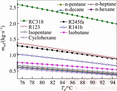
Fig. 5 Variation of mass flow rate of different working fluids versus evaporating temperature
4.2 Net power output
Figure 6 demonstrates the variation of the net power output of different working fluids versus the evaporating temperature. As shown in Fig. 6, the net power output first increases and reaches its maximum, and then decreases with the increment of the evaporating temperature, which applies to all the working fluids. It also can be seen that the Wnet corresponding to Te,turning is the optimal Wnet for each working fluid, so Te,turning can be regarded as the Te,opt. In essence, the two parameters can be deemed as one. From Eq. (32), the net power output, Wnet, is proportional to Wt, which is due to that the values of the power consumptions, Wp, Whp and Wcp, are relatively much smaller compared with Wt. The maximum net power output is 20.67 kW for RC318 when the evaporating temperature comes to 38��, while the cyclohexane keeps the minimum net power output at the same evaporating temperature. For net power output,the performance of the working fluids decreases in the order: RC318, R245fa, isobutane, R123, isopentane, n-pentane, R141b, n-hexane, n-heptane, n-decane and cyclohexane. From the cost of turbine, it can be obtained that a larger mwf will increase the thickness of the wall of turbine, so the cost of turbine will increase.
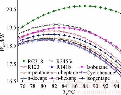
Fig. 6 Variation of net power output of different working fluids versus evaporating temperature
The saturated vapor outlet temperature versus the evaporating temperature for various working fluids is presented in Fig. 7. As shown, the rise of Tsv,out is proportional with Te, and the change rate of Tsv,out to Te is almost the same for all working fluids. The Tsv,out of the RC318 is always lesser than other working fluids at the same evaporating temperature, and it ranges from 42.98 ��C for Te=75 ��C to 59.31 ��C for Te=95 ��C, whereas the Tsv,out of the cyclohexane is greater than the left working fluids in the same situation, and the range of variation is from 65.93 ��C for Te=75 ��C to 87.38 ��C for Te=95 ��C. The differences between the Tsv,out of alkanes, like n-pentane, n-heptane, n-hexane and n-decane, are in a small range. In this work, the heat source is saturated vapor, which means that there are latent heat and sensible heat existing in the process of heat transfer. From Eq. (22), it can be obtained that with the inlet temperature of the evaporate fixed, the increase of the tsv,out decreases the quantity of heat transferred from the heat source.
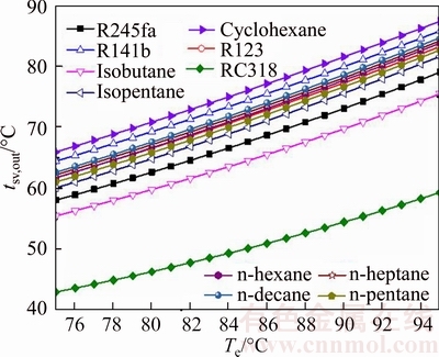
Fig. 7 Saturated vapor outlet temperature versus evaporating temperature for various working fluids
4.3 Irreversible loss
Figure 8 demonstrates the influence of the evaporating temperature on the irreversibility of the system for various working fluids. The irreversible loss of the system contains the irreversible loss caused by condenser, evaporator, pump and turbine, respectively. It can be seen from Fig. 8 that the irreversible loss of the system decreases with the increment of evaporating temperature. The irreversible loss of the system of RC318 is the largest in the 11 kinds of working fluids, which ranges from 35.23 kW to 29.39 kW. Whereas, the value Icyclohexane is the least value and its change range is from 28.53 kW to 18.16 kW. At the same time, the changing curve of In-hexane, In-pentane, In-heptane and In-decane is almost coincident. Combined with Fig. 7, it can be obtained that with the heat that working fluids absorbed from heat source reducing, the irreversible loss of the system decreases together.
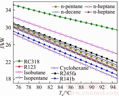
Fig. 8 Influence of evaporating temperature on irreversibility of system for various working fluids
Figure 9 illustrates the entropy generation of the system with the evaporating temperature for various working fluids. The entropy generation Sg is composed of the system Sg,c, Sg,e, Sg,p and Sg,t, in which subscripts c, e, p and t represent condenser, evaporator, pump and turbine, respectively. Among them, the entropy generation caused by evaporate is greater than other system components for each working fluid. As shown in Fig. 9, the entropy generation of RC318 is the biggest of all working fluids, whereas Sg,cyclohexane is minimum under the same te, from 0.1048 kJ/K to 0.08785 kJ/K and 0.08599 kJ/K to 0.05431 kJ/K, respectively. From Eq. (31), it can be obtained that Sg is related with the mass flow rate of saturated vapor and cooling water and the entropy difference of saturated vapor and cooling water in the inlet and outlet of evaporator and condenser, respectively. Whereas msv, Sgw,in, Scw,out and Scw,in are unchanged, so the variation of Sg depends on mcw and Sgw,out. Combined Fig. 6, it can be obtained that the value of mcw is much greater than msv (msv=1 kg/s), and the mass flow rate of cooling water plays a decisive role. So the variation trend of Sg is consistent with that of mcw.
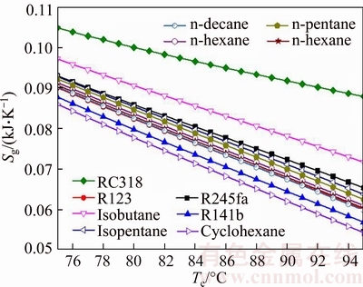
Fig. 9 Entropy generation of system with evaporating temperature for various working fluids
4.4 Mass flow rate of cooling water
The variation of the mass flow rate of the cooling water versus the evaporating temperature for various fluids is shown in Fig. 10. Evidently, as shown in Fig. 10, the mass flow rate of the cooling water is gradually reduced with the increase of evaporating temperature. The value of mcw,RC318 is greater than other medium, and its variation range is from 16.2 kg/s to 12.93 kg/s with Te rises from 75 ��C to 95 ��C, while mcyclohexane varying from 11.71 kg/s to 7.562 kg /s, which is less than other working fluids. From Eq. (15), it can be obtained that mcw is proportional to mwf and the difference between h2 and h3, and it is inversely proportional to c and Tcw. On account of the value of h5, c and Tcw are fixed, so just mwf and h2 are taken in account. Combined with Fig. 5, as Te increases, the mass flow rate of working fluids, mwf, decreases. Whereas the enthalpy of condenser inlet, h2, increases with Te. But the absolute value of mwf to Te is greater than the value of h2 to Te, so the rising in Te leads to the decreasing of mcw.
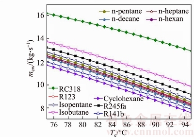
Fig. 10 Variation of mass flow rate of cooling water versus evaporating temperature for various fluids
4.5 Thermal conductance
Figure 11 illustrates the thermal conductance of condenser versus the evaporating temperature for different working fluids. Clearly, as presented in Fig. 11, the thermal conductance of condenser decreases with the rising of evaporating temperature for each working fluid. In all the working fluids, KAc,RC318 is the biggest, which ranges from 178 kW/��C to 128.8 kW/��C; whereas KAc,n-decane is the smallest, the variation range of which is 136.9 kW/��C to 77.92 kW/��C. By calculating, the change rate of the gap between the working fluids, which is adjacent to each other in Fig. 7, is not very big. The value of KAc to Te can be approximately regarded as constant and is different from each other for all working fluids. From Eq. (12), it can be obtained that KAc is proportional to the thermal load in condenser, and is inversely proportional to the log mean temperature difference in condenser. From Fig. 3, the rising of Tsv,out decreases the thermal load in evaporator, so Qc will also diminish as Qe, moreover, ��Tc is proportional to Te.
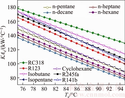
Fig. 11 Thermal conductance of condenser versus evaporating temperature for different working fluids
Figure 12 illustrates the thermal conductance of evaporator versus the evaporating temperature for different working fluids. Apparently, it can be got from Fig. 12 that the maximum value of KAe appeared when the working fluid is RC318; the minimum value of KAe occurred when cyclohexane was used as working fluid, whereas the shape of the curve is different for different working fluids. The change trend of RC318 first increases when KAe,RC318 reaches the maximum value 22.44 kW/��C for Te=80 ��C, and then decreases with the increment of Te like a straight line; each change rate of the rest curves in Fig. 8 can be approximately regarded as constant. From Eq. (26), it can be obtained that KAe is determined by the thermal load in evaporator and the log mean temperature difference in the evaporator. The rising of the Te results in the decrease of the log mean temperature difference in the evaporator and the thermal load of the evaporator. For RC318, when Te<80 ��C, the change rate of ��T to Te is greater than that when Te>80 ��C. The variation range of KAe,RC318 is from 22.17 kW/��C to 20.72 kW/��C, and the variation range of KAe,cyclohexane is from 13.08 kW/��C to 10.28 kW/��C.
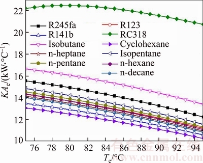
Fig. 12 Thermal conductance of evaporator versus evaporating temperature for different working fluids
Figure 13 illustrates the total thermal conductance of system versus the evaporating temperature for different working fluids. Clearly, as presented in Fig. 13, KA decreases with the increase of Te, and the change trend of KA is semblable with KAc for all working fluids. From Eq. (30), KA is got by KAc and KAe. It can be clearly obtained from Figs. 11 and 12 that KAc is much greater than KAe because of the smaller temperature difference in the condenser. So KAc is the key factor which determines the variation trend of KA, and that is the reason why KA and KAc show the similar change rules for every working fluid. Put Figs. 7�C9 together, it can be seen that Qc and Qe are both reduced as the Tsv,out increases, and the total KA also decreases with the change of Qc and Qe. The maximum value, KARC318, ranges from 200.2 kW/��C to 149.5 kW/��C, whereas the minimum value, KAn-decane, ranges from 151 kW/��C to 88.78 kW/��C.
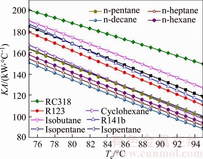
Fig. 13 Total thermal conductance of system versus evaporating temperature for different working fluids
4.6 Volumetric flow rate
Figure 14 shows the variation of the volumetric flow rate versus the evaporating temperature for different working fluids. Obviously, as presented in Fig. 14, it can be obtained that the VFR of the n-decane is higher than that of other working fluids, and the VFR of the isobutene is lower than that of the rest working fluids. It also can be known that the system condensing pressure can be regarded as a constant due to the environment condition is unchanged. So Te is the only factor affecting the size of VFR: VFR is proportional to Te. From MACCHI et al [46], there exists an inversely proportional relationship between VFR and turbine efficiency: lower values of VFR deliver higher turbine efficiency. From the point of economic, INVERNIZZI et al [47] presented that in order to achieve a turbine efficiency higher than 80%, the VFR should be lower than 50. So the maximum and minimum of the turbine efficiency are isobutane and n-decane, respectively. But, for all working fluids, the turbine efficiency is higher than 80%. Moreover, it can be got that the length of the turbine will increase with the increase of the VFR, then the cost of turbine will also increase. The variation range of VFRn-decane is from 12.02 for Te=75 ��C to 28.66 for Te=95 ��C, meanwhile the variation range of VFRisobutene is from 3.198 for Te=75 ��C to 5.121 Te=95 ��C.
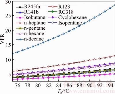
Fig. 14 Variation of volumetric flow rate versus evaporating temperature for different working fluids
4.7 Figure of merit
Figure 15 shows the variation of the figure of merit (FOM, Fom) versus the evaporating temperature for different working fluids. The concept of FOM is put forward by MIKIELEWICZ [48], FOM is treated as an important index to evaluate the merits of the working fluids, which is expressed as follows:
 (39)
(39)
where Ja is the ratio of cp,e and re, cp,e and re are the sensible heat and the latent heat of vaporization of working fluids, respectively.
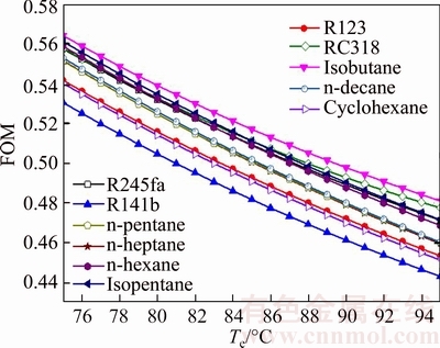
Fig. 15 Variation of figure of merit versus evaporating temperature for different working fluids
As shown in Fig. 15, the FOMs of all working fluids have the consistent trends which decrease with the increases of te. Among them, FOMisobutane is obviously higher than that for other working fluids, and FOMR141b is evidently lower than that for the left working fluids. So the performance of the isobutane is excellent than that of others. FOMisobutane ranges from 0.5641 to 0.4811 and FOMR141b ranges from 0.5305 to 0.4433, when Te increases from 75 ��C to 95 ��C. From Eq. (39), it can be seen that FOM is directly proportional to the sensible heat of the working fluid (cp,e), and is inversely proportional to the evaporating temperature (Te) and the latent heat of the working fluid (re). Combined Figs. 11, 13 and 14, there is a rule that FOM is inversely proportional to thermal efficiency and exergy efficiency.
4.8 Size parameter
As the analysis of working fluids is described from the point of thermodynamics, the size parameter (SP, Ps) is brought up to measure the turbine efficiency for the different working fluids. The parameter SP is defined by MACCHI et al [46] as follows:
 (40)
(40)
where Vout stands for volume flow rate of the working fluids at the outlet of the turbine, and h2s is specific enthalpy at the turbine outlet experiencing an isentropic process.
Figure 16 shows the variation of the size parameters versus the evaporating temperature for different working fluids. As presented in Fig. 16, it can be clearly seen that SPn-decane is significantly higher than the values of other working fluids, and SPisobutane is lower than that of other working fluids. The value of n-decane changes from 2.899 for Te=75 ��C to 2.408 for Te=95 ��C, and the SP of isobutane ranges from 0.5641 for Te=75 ��C to 0.4811 for Te=95 ��C. The change trend of FOM decreases with the increase of Te. According to Ref. [20], a higher value of SP results in higher turbine efficiency. Then combined Fig. 12 and Eq. (40), it can be obtained that the enthalpy difference of inlet and outlet increases with increasing Te; at the same time, the mass flow rate of working fluids increases also. That is the reason why SP becomes smaller with the increase of Te. From the point view of economic, a higher SP will increase the size of turbine, so the cost of turbine will also increase.
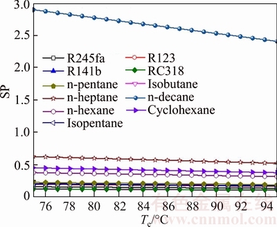
Fig. 16 Variation of size parameters versus evaporating temperature for different working fluids
4.9 System efficiency
Figures 17 and 18 show the exergetic efficiency and thermal efficiency of system versus the evaporating temperature for different working fluids. Evidently, it can be seen from Figs. 17 and 18 that ��ex and ��th are proportional to Te for all working fluids. Whereas the ratio of ��ex to Te is not consistent and it becomes smaller and smaller, but the variation trend is almost unchanged. From Eq. (38), it can be seen that ��ex is determined by Wnet and the exergy at the inlet and outlet of the evaporator for saturated vapor. From Fig. 7, increasing Te will result in increasing Tsv,out, and the difference between EXsv,in and EXsv,out will reduce with the increase of Tsv,out. From Fig. 6, it can be known that Wnet first increases and then decreases. That is the reason why the variation trends do not keep consistent. For all working fluids, the maximal value of the ��ex is ��ex,cyclohexane, which ranges from 32.37% for Te=75 ��C to 39.51% for Te=95 ��C. On the contrary, the ��ex,RC318 is the minimum value and its range is from 28.75% for Te=75 ��C to 33.37% for Te=95 ��C.
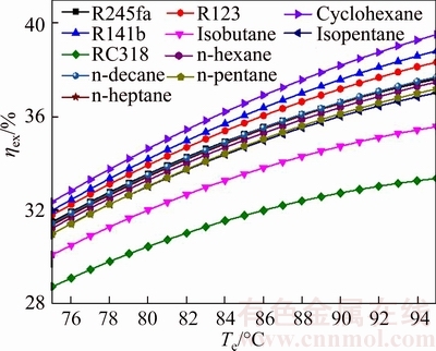
Fig. 17 Exergetic efficiency of system versus evaporating temperature for different working fluids
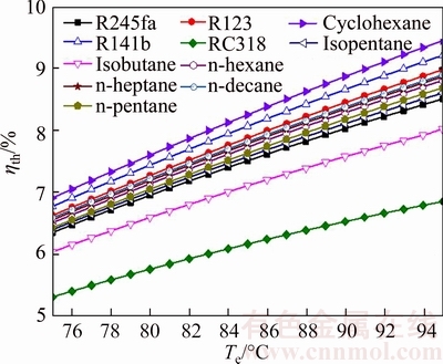
Fig. 18 Thermal efficiency of system versus evaporating temperature for different working fluids
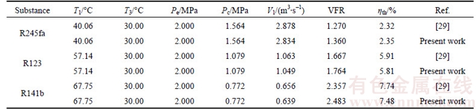
Table 1 Validation of numerical model with previous published data [29] for various fluids-based ORC
From Eq. (37), it can be got that ��th relies on Wnet, mwf and the enthalpy at the inlet and outlet of the evaporator for saturated vapor. For all working fluids, the maximal value of ��th is ��th,cyclohexane, which ranges from 6.914% for Te=75 ��C to 9.451% for Te=95 ��C; on the contrary, ��th,RC318 is the minimum value and its range is from 5.317% at Te=75 ��C to 6.856% at Te=95 ��C.
From the above analysis, it can be obtained that the evaporating temperature is the most key parameter for the system performance of the ORC and should be optimized in engineering applications. Furthermore, the optimal working fluid differs with one evaluation index to another. Overall, the cyclohexane has excellent comprehensive performance.
5 Validation
Numerical solution is validated with the results of SALEH et al [29] for various working fluids-based ORC without regenerator under the same operating conditions. The results of present solutions show a very good agreement with the results in the reference, as shown in Table 1. The discrepancies mainly derive from the selection of equation of state (EOS) that the BACKONE EOS is adopted in reference while the fundamental EOS is selected in this work.
6 Conclusions
Eleven pure working fluids (as categorized into alkanes and fluorinated alkanes) are screened for organic Rankine cycle driven by the latent heat. The main conclusions are summarized as follows.
1) The evaporating temperature is the most important parameter of the ORC, and the optimal evaporating temperature will minimize the irreversible loss and the entropy generation and is different with the working fluid, so it should be optimized to obtain the optimal system performance, especially for the low- and medium-grade heat sources.
2) RC318 shows the highest net power output as a result of the lowest outlet temperature of the heat source, so the corresponding system efficiency is the lowest. Moreover, the high GWP value also limits the utilization of RC318.
3) The n-decane has the lowest total thermal conductance, but its volumetric flow ratio and size parameter are too high to restrict its application.
4) The cyclohexane suggests the highest thermal and exergetic efficiencies, and it shows outstanding overall performances and can be used in engineering applications.
The cycle parameters and the working fluid selection are the two main aspects that should be considered for the actual ORC plants, and the system performance must be optimized based on the temperature level of the heat source and heat sink.
References
[1] QUOILIN S, OROSZ M, HEMOND H, LEMORT V. Performance and design optimization of a low-cost solar organic Rankine cycle for remote power generation [J]. Sol Energy, 2011, 85: 955�C966.
[2] KANOGLU M. Exergy analysis of dual-level binary geothermal power plant [J]. Geothermics, 2002, 31: 709�C724.
[3] ZHANG Jian-hua, ZHOU Ye-li, LI Ying, HOU Guo-lian, FANG Fang. Generalized predictive control applied in waste heat recovery power plants [J]. Appl Energy, 2013, 102: 320�C326.
[4] SUN Fa-ming, IKEGAMI Y, JIA Bao-ju, ARIMA H. Optimization design and exergy analysis of organic rankine cycle in ocean thermal energy conversion [J]. Appl Ocean Res, 2012, 35: 38�C46.
[5] YAMAMOTO T, FURUHATA T, ARAI N, MORI K. Design and testing of the organic Rankine cycle [J]. Energy, 2001, 26: 239�C251.
[6] HETTIARACHCHI H D M, GOLUBOVIC M, WOREK W M, IKEGAMI Y. Optimum design criteria for an organic Rankine cycle using low-temperature geothermal heat sources [J]. Energy, 2007, 32: 1698�C1706.
[7] MAIZZA V, MAIZZA A. Unconventional working fluids in organic Rankine-cycles for waste energy recovery systems [J]. Appl Therm Eng, 2001, 21: 381�C390.
[8] CHEN Hui-juan, GOSWAMI D Y, ELIAS K, STEFANAKOS E K. A review of thermodynamic cycles and working fluids for the conversion of low-grade heat [J]. Renew Sustain Energy Rev, 2010, 14: 3059�C3067.
[9] DIPIPPO R. Second law assessment of binary plants generating power from low-temperature geothermal fluids [J]. Geothermics, 2004, 33: 565�C586.
[10] MAGO P J, SRINIVASAN K K, CHAMRA L M, SOMAYAJI C. An examination of exergy destruction in organic Rankine cycles [J]. Int J Energ Res, 2008, 32: 926�C938.
[11] ZHU Jia-ling, ZHANG Wei. Optimization design of plate heat exchangers (PHE) for geothermal district heating systems [J]. Geothermics, 2004, 33: 337�C347.
[12] CLEMENTE S, MICHELI D, REINI M, TACCANI R. Energy efficiency analysis of organic Rankine cycles with scroll expanders for cogeneration applications [J]. Appl Energy, 2012, 97: 792�C801.
[13] WANG E H, ZHANG H G, ZHAO Y, FAN B Y, WU Y T, MU Q H. Performance analysis of a novel system combining a dual loop organic Rankine cycle (ORC) with a gasoline engine [J]. Energy, 2010, 43: 385�C395.
[14] LI Jing, PEI Gang, JI Jie. Optimization of low temperature solar thermal electric generation with organic Rankine cycle in different areas [J]. Appl Energy, 2010, 87: 3355�C3365.
[15] MAVROU P,PAPADOPOULOS A I, SEFERLIS P, LINKE P, VOUTETAKIS S. Selection of working fluid mixtures for flexible organic Rankine cycles under operating variability through a systematic nonlinear sensitivity analysis approach [J]. Appl Therm Eng, 2015, 89: 1054�C1067.
[16] HE Si-nian, CHANG Hua-wei, ZHANG Xiao-qing, SHU Shui-ming, DUAN Chen. Working fluid selection for an organic Rankine cycle utilizing high and low temperature energy of an LNG engine [J]. Appl Therm Eng, 2015, 90: 579�C589.
[17] WU Yuan-dan, ZHU Ya-dong, YU Li-jun. Thermal and economic performance analysis of zeotropic mixtures for organic Rankine cycles [J]. Appl Therm Eng, 2016, 96: 57�C63.
[18] DESAI N B, BANDYOPADHYAY S. Thermo-economic analysis and selection of working fluid for solar organic Rankine cycle [J]. Appl Therm Eng, 2016, 95: 471�C481.
[19] MAGO P J, CHAMRA L M, SRINIVASAN K, SOMAYAJI S. An examination of regenerative organic Rankine cycles using dry fluids [J]. Appl Therm Eng, 2008, 28: 998�C1007.
[20] XI Huan, LI Ming-jia, XU Chao, HE Ya-ling. Parametric optimization of regenerative organic Rankine cycle (ORC) for low grade waste heat recovery using genetic algorithm [J]. Energy, 2013, 58: 473�C482.
[21] PEI Gang, LI Jing, JI Jie. Analysis of low temperature solar thermal electric generation using regenerative organic Rankine cycle [J]. Appl Therm Eng, 2010, 30: 998�C1004.
[22] FERNNDEZF J, PRIETO M M, SUAREZ I. Thermodynamic analysis of high temperature regenerative organic Rankine cycle using siloxanes as working fluids [J]. Energy, 2011, 36: 5239�C5249.
[23] ROY J P, MISRA A. Parametric optimization and performance analysis of a regenerative organic Rankine cycle using R-123 for waste heat recovery [J]. Energy, 2012, 39: 227�C235.
[24] LI Tai-lu, WANG Qiu-lin, ZHU Jia-ling, HU Kai-yong, FU Wen-cheng. Thermodynamic optimization of organic Rankine cycle using two-stage evaporation [J]. Renew Energy, 2015, 75: 654�C664.
[25] BORSUKIEWICZ-GOZDUR A, NOWAK W. Maximising the working fluid flow as a way of increasing power output of geothermal power plant [J]. Appl Therm Eng, 2007, 27: 2074�C2078.
[26] LI Mao-qing, WANG Jiang-feng, HE Wei-feng, GAO Lin, WANG Bo, MA Shao-lin, DAI Yi-ping. Construction of preliminary test of a low-temperature regenerative organic Rankine cycle (ORC) using R123 [J]. Renew Energy, 2013, 57: 216�C222.
[27] BADR O, O��CALLAGHAN P W, PROBERT S D. Thermodynamic and thermophysical properties of organic working fluids for Rankine-cycle engines [J]. Appl Energy, 1985, 19: 1�C40.
[28] HUNG T C, SHAI T Y, WANG S K. A review of Organic Rankine Cycles (ORCs) for the recovery of low-grade waste heat [J]. Energy, 1997, 22(7): 661�C667.
[29] SALEH B, KOGLBAUER G, WENDLAND M, FISHER J. Working fluids for low temperature organic Rankine cycles [J]. Energy, 2007, 32: 1210�C1221.
[30] YARI M. Performance analysis of the different organic Rankine cycles (ORCs) using dry fluids [J]. Int J Exergy, 2009, 6(3): 323�C342.
[31] YARI M. Exergetic analysis of various types geothermal power plants [J]. Renew Energy, 2010, 35(1): 112�C121.
[32] DESAI N B, BANDYOPADHYAY S. Process integration of organic Rankine cycle [J]. Energy, 2009, 34: 1674�C1686.
[33] HUNG T C, WANG S K, KUO C H, PEI B S, TSAI K F. A study of organic working fluids on system efficiency of an ORC using low-grade energy sources [J]. Energy, 2010, 35: 1403�C1411.
[34] LIU B, CHIEN K, WANG C. Effect of working fluids on organic Rankine cycle for waste heat recovery [J]. Energy, 2004, 29: 1207�C1217.
[35] PAPADOPOULOS AI, STIJEPOVIC M, LINKE P. On the systematic design and selection of optimal working fluids for organic Rankine cycles [J]. Appl Therm Eng, 2010, 30: 760�C769.
[36] CHEN hui-juan, GOSWAMI D Y, RAHMAN M M, STEFANAKOS E K. A supercritical Rankine cycle using zeotropic mixture working fluids for the conversion of low-grade heat into power [J]. Energy, 2011, 36: 549�C555.
[37] LAKEW A A, BOLLAND O. Working fluids for low-temperature heat source [J]. Appl Therm Eng, 2010, 30: 1262�C1268.
[38] PASETTI M, INVERNIZZI C M, IORA P. Thermal stability of working fluids for organic Rankine cycles: An improved survey method and experimental results for cyclopentane, isopentane andn-butane [J]. Appl Therm Eng, 2014, 73: 764�C774.
[39] LI Zi-shen, LI Wei-yi, XU Bo-rui. Optimization of mixed working fluids for a novel trigeneration system based on organic Rankine cycle installed with heat pumps [J]. Appl Therm Eng, 2016, 94: 754�C762.
[40] MAVROU P, PAPADOPOULOS A I, STIJEPOVIC M Z, SEFERLIS P, LINKE P, VOUTETAKIS S. Novel and conventional working fluid mixtures for solar Rankine cycles: Performance assessment and multi-criteria selection [J]. Appl Therm Eng, 2015, 75: 384�C396.
[41] LEMMON E W, HUBER M L, MCLINDEN M O. NIST standard reference database 23: Reference fluid thermodynamic and transport properties-REFPROP, version 9.0 [R]. National Institute of Standards and Technology, Standard Reference Data Program, Gaithersburg, 2010.
[42] CALM J M, HOURAHAN G C. Refrigerant date update [J]. Heating/Piping/Air Conditioning Engineering, 2007, 79: 50�C64.
[43] DEFIBUAGH D R, GILLIS K A, MOLDOVER M R, SCHMIDT J W, WEBER L A. Thermodynamic properties of CHF(2)-CF(2)- CH(2)F, 1,1,2,2,3- pentafluoropropane [J]. Int J Refrig, 1996, 19(4): 285�C294.
[44] OUTCALT S L, MCLINDEN M O. A modified Benedicte Webbe Rubin equation of state for the thermodynamic properties of R152a (1.1-difluoroethane) [J]. J Phys and Chem Ref Data, 1996, 25(2): 605�C636.
[45] TILLNER-ROTH R, BAEHR H D. An international standard formulation for the thermodynamic properties of 1,1,1,2- tetrafluoroethane (HFC-134a) covering temperatures from 170 K to 455 K at pressures up to 70 MPa [J]. J Phys and Chem Ref Data, 1994, 23: 657�C729.
[46] MACCHI E, PERDICHIZZI A. Efficiency prediction for axial-flow turbines operating with non conventional fluids [J]. J Eng Gas Turb Power, 1981, 103: 718�C724.
[47] INVERNIZZI C, IORA P, SILVA P. Bottoming micro-Rankine cycles for micro-gas turbines [J]. Appl Therm Eng, 2007, 27: 100�C110.
[48] MIKIELEWICZ D, MIKIELEWICZ J. A thermodynamic criterion for selection of working fluid for subcritical and supercritical domestic micro CHP [J]. Appl Therm Eng, 2010, 30: 2357�C2362.
(Edited by FANG Jing-hua)
Cite this article as:
XU Peng, LU Jian, LI Tai-lu, ZHU Jia-ling. Thermodynamic optimization and fluid selection of organic Rankine cycle driven by a latent heat source [J]. Journal of Central South University, 2017, 24(12): 2829�C2841.
DOI:https://dx.doi.org/https://doi.org/10.1007/s11771-017-3698-zFoundation item: Project(51406130) supported by the National Natural Science Foundation of China
Received date: 2016-02-29; Accepted date: 2016-05-17
Corresponding author: LI Tai-lu, Lecturer, PhD; Tel: +86�C22�C28305107; E-mail: litl@tcu.edu.cn
Abstract: Organic Rankine cycle (ORC) is applicable for the heat-work conversion. Whereas, there also exist a lot issues that influence the efficiency and the cost of the system. In this work, eleven pure working fluids (as categorized into alkanes, and fluorinated alkanes) are investigated based on the first and second law of thermodynamics. The major objective is to obtain the most suitable working fluid for the latent heat source. The results show that the working fluid is an important factor of the system performance. The heat absorption of the working fluid in the evaporator is inversely proportional to the evaporating temperature, but the thermal and exergetic efficiencies are just the opposite. RC318 has the highest net power output and the lowest outlet temperature of the heat source, but its global warming potential (GWP) value is too high. The cyclohexane shows the highest thermal efficiency among the fluids investigated. Moreover, the figure of merit (FOM) of the isobutane is higher than that of other working fluids. Overall, the cyclohexane shows that the optimal comprehensive performance is more feasible for medium grade heat source in engineering applications.
