
J. Cent. South Univ. (2016) 23: 969-974
DOI: 10.1007/s11771-016-3144-7

CFD study of flow-diffusion process in Y-shape micromixer
CHEN Zhuo(��), ZHANG Rui-qi(�����), WANG Xiao-na(������)
School of Energy Science and Engineering, Central South University, Changsha 410083, China
 Central South University Press and Springer-Verlag Berlin Heidelberg 2016
Abstract:
A CFD simulation was carried out to investigate the mixing process in a Y-shape micromixer with the software Fluent 6.3. The definition of the ��diffusion angle�� is proposed to describe the molecular diffusion process associated with the flow at low Reynolds number. The linear relationship between the diffusion angle and the Peclet number (Pe) is determined by both theoretical analysis and numerical simulation. Moreover, the simulation results reveal that the diffusion angle is only related to the Peclet number whilst it is irrelevant to the changes of Re (Reynolds number) and Sc (Schmidt number). The range of Peclet number and Reynolds number for experimental measurement are also suggested as Pe��10000 and Re��10.
Key words:
simulation; flow-diffusion process; molecular diffusion; Y-shape micromixer��
1 Introduction
Over past decades, micro-fluidic systems have been successfully designed and widely used in the fields of chemical, biochemical, and biomedical engineering [1�C3]. Examples include dynamic cell separators [4], mass spectrometer delivery modules [5], as well as surface patterning of cells and proteins [6]. For all these applications, the micro-scale mixing seems inevitable for either providing an interfacial contact area between reactants in micro-reactor or as a device to control mixing in the micro-scale.
Due to the low Reynolds numbers (typically less than 1), the flow in a microchannel is dominated by laminar flow and the mass transfer process relies greatly on the molecular diffusivities of liquids [7], for which the flow and diffusion occur simultaneously but in two perpendicular directions. For such a process, most literatures focused on the enhancement of the mixing efficiency through selecting different structure and operational parameters, such as volume rate, aspect ratio as well as the mixing angle in the micromixers, by experimental investigations or numerical simulations [8�C11]. A few literatures reported about the mechanism of diffusion and mixing process in the microchannels [12�C15]. For instance, WANG [16] indicated that the Reynolds number influences the diffusion critically and the lower the Reynolds number is, the wider the species diffuse. ZHENG [17] indicated that when two or more reagents are injected into the microchannel, the reaction and diffusion occurs only in the contact interface and the flow pattern remains the same, which has high stability and good reproducibility. The flow and diffusion process both contribute to the mixing performance in microchannels. However, the previous studies hardly associate the fluid flow with the diffusion process in microchannels.
To investigate the relationship between the mass transfer and fluid flow in Y-shape micromixer, both theoretical analysis and numerical simulation were carried out. The influence of Re, Pe and Sc on diffusion was also discussed in this work, which aims to lay down a foundation for future experimental measurement of liquid diffusivity.
2 Theoretical analysis
The fluid flow in a micromixer is typically characterized by its low Reynolds number, thus the mixing process depends mainly on the molecular diffusion of the liquids.
As illustrated in Fig. 1, when two streams are fed side by side into a channel, the distance that the fluid moves along the channel within a given time period t is
 (1)
(1)
where u is the flow velocity, and l is the distance that the fluid moves during the time.
In the meantime, when the diffusion process is purely dependent on the molecular scale at an extremely low Re, the width that one species (Species A) diffuses across the channel into the other species (Species B) can be determined by the Fick��s law as
 (2)
(2)
where �� is the vertical diffusion distance, and D is the diffusivity of the liquid.
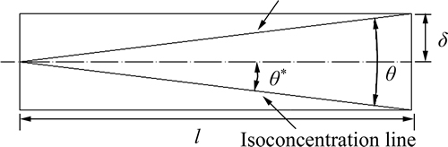

Fig. 1 Schematic diagram of diffusion angle
As the fluid flow and the diffusion process occur in two perpendicular directions, the distances that the liquid travels downstream and the width that it diffuses across the channel forms an angle, which keeps unchanged when the fluid flows through the channel. This angle is then defined as the diffusion angle by selecting a concentration interface as the specified edges, as illustrated in Fig. 1.
The tangent of half the diffusion angle can be easily obtained as
 (3)
(3)
where ��* is half of the diffusion angle,�� is the vertical diffusion distance, and l is the distance that the fluid moves along the channel.
Substituting Eq. (1) and Eq. (2) into Eq. (3), the expression of tan2��* can be obtained as
 (4)
(4)
As the Peclet number is defined as the ratio of the mass transfer caused by fluid convection to that caused by the molecular diffusion, the dimensionless parameter Pe is introduced here into Eq. (4), and it is rewritten as
 (5)
(5)
where W is the width of the micro-channel.
If put in the logarithmic format, Eq. (4) is then changed into
 (6)
(6)
where the constant C equals
 (7)
(7)
As indicated by Eq.(7), lgtan��*is in a linear relationship with lgPe, and the slope between the two variables is �C0.5. And more importantly, the logarithm of the diffusion angle �� varies only with the Peclet number of the flow. Therefore, once the diffusion tangle of a parallel flow is determined, the liquid diffusivity can then be calculated using the above equation, which makes it possible for experimental measurement of the liquid diffusivity without disturbing the flow.
3 Numerical models
3.1 Computational geometry
Simulation was carried out to examine the universality of Eq. (7) for different liquids in reality. To reduce the grid numbers, the computational domain only includes the straight channel of a Y-shape micromixer by chopping off the inlet passages which are used to introduce the liquids. Moreover, limited by the computing resource, a two-dimensional model is adopted to effectively reduce the gird numbers but to achieve the desired accuracy. Thus, the computational domain is simplified to be a rectangle which is 1000 ��m in length and 200 ��m in width, as shown in Fig. 2.
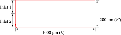
Fig. 2 Physical model for Y-shape micromixer
One thing that needs to be noted is that, in theory, a fully developed flow can be reached only after an infinite distance which is called the entrance effect. So, the entrance effect must be taken into account in simulations of real flow, especially when the study is focused on the fully developed flow region.
Simulation is then carried out to determine the entrance length for fluid flow within the ranges of the Reynolds numbers. A typical result is given in Fig. 3, showing the velocity profile along the channel width at Re=5 at different channel lengths of X=50, X=100, X=200 and X=400 ��m, respectively.
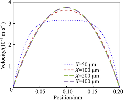
Fig. 3 Velocity distribution at different positions along X axis
It can be found that the flow at the channel length of X=200 ��m and below keeps the same, which means it reaches the fully developed state. However, to be conservative enough, the channel section between X= 400 ��m to X=800 ��m is selected for data processing in the following work, because it is far enough away from the entrance effect area.
3.2 Mathematical model
Several simplifications are made for the numerical model of the fluid flow and diffusion process in the Y-shape micromixer. These include:
(1) The two identical fluids fed into the channel are of the same viscosity and density;
(2) The temperature in the micro-mixer is considered to be constant;
(3) Chemical reactions are not considered because no reaction is involved in the mixing process;
(4) Due to the scale effect, gravity is ignored as well.
Based on the above simplifications, a steady-state, incompressible, laminar flow numerical model is developed with Fluent 6.3 to investigate the flow- diffusion process inside the micromixer. The governing equations include equations of continuity, momentum and diffusion, which are:
Continuum equation:
 (10)
(10)
Momentum equation:
 (11)
(11)
Diffusion equation:
 (12)
(12)
where u is the fluid velocity, �� is the fluid density, �� is the fluid viscosity, and p is the fluid pressure.
3.3 Boundary conditions
The boundary conditions include all the inlets, outlet and walls in the computational domain, of which the two liquid inlets are set to be velocity inlets, the outlet is set to be the outflow and all the walls are set to be no-slip walls.
3.4 Mesh independent analysis
The mesh size is of great importance for high accuracy of the computation. Although generally the smaller the mesh size is, the more accurate the simulation results are, the excessively small meshes always demand more computation time and resources. Therefore, comprise must be made between the accuracy and the computation effort for all numerical simulation problems.
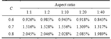
For the case introduced in this work, as the molecular diffusion process progresses much slower than the fluid flow, finer grids are used across the channel width compared to the grids along the channel length. Meshes of different aspect ratios have been tested, and the diffusion angles with different concentration interfaces are extracted from the simulation results, i.e. the slopes between lgtan��* and lgPe, are calculated and compared to the theoretical slope in Eq. (6). The relative concentration of introduced fluids is set to be 0 and 1 respectively, thus the relative concentrations of the mixing are within the range of 0�C1. The data of concentration of 0.6, 0.7 and 0.8 (C=0.6, C=0.7, C=0.8) are extracted in the following work. The slopes for C=0.6, C=0.7 and C=0.8 with meshes of different aspect ratios are summarized in Table 1. All the slopes are very close to the theoretical value. The relative errors between the simulation results and theoretical values listed in Table 2 range from 0.843% to 2.085%, which are considered to be acceptable for the purpose of the research. Comparatively, the mesh with aspect ratio of 1:40 (unit grid width in diffusion direction to unit grid length in flow direction) results in both the least grid numbers and the best accuracy, therefore, this mesh is adopted for the entire simulation study.
Table 1 Slopes with meshes of different aspect ratios
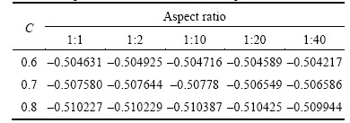
Table 2 Computation deviations with meshes of different aspect ratios
4 Results and discussion
4.1 Simulation results of water
Simulation is launched for the common substance water. The diffusion contours at different Peclet numbers are shown in Fig. 4 when Re=2. It can be clearly seen that liquids diffuse mutually along the channel and the diffusion angle decreases with the increase of the Peclet number.
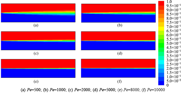
Fig. 4 Diffusion contours of Y-style micromixer at different Peclet numbers:
The relationship between the diffusion angle and the Reynolds number for C=0.6, 0.7 and 0.8 are shown respectively in Fig. 5, Fig. 6 and Fig. 7. At a specified Peclet number, the diffusion angle remains nearly unchanged when Re��10. Thus, the diffusion angle is irrelevant to Reynolds number in such low Reynolds number condition. When Re>10, the diffusion angle decreases with the increase of the Reynolds number. This indicates that, with the Reynolds number increasing, velocity increases and the convection cannot be ignored anymore. The measurement for diffusion coefficient calls for elimination of convection to simplify the mixing process to depend on diffusion purely. Therefore, the measurement for the diffusion coefficient is suggested to be carried out with the range of Re=0�C10.
The relationship between lgPe and lgtan��* for C=0.6, 0.7, 0.8 are shown in Fig. 8. The common feature at different concentration boundaries is that lgtan��* is in a linear relationship with lgPe and the slopes between the two variables are negative. However, inflection points appear at Pe=15000, especially at the concentration interface of 0.7 and 0.8. On one hand, the mesh accuracy is partly responsible for the appearance of the inflection point to some extent; On the other hand, with the Pecletnumber increasing, the inlet velocity of fluid increases, which increases the influence of convection.
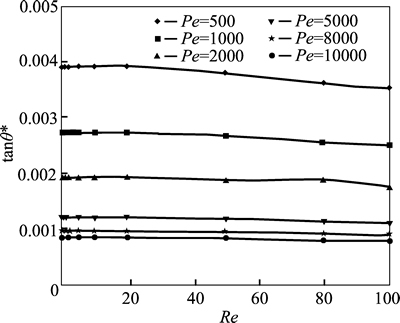
Fig. 5 Diffusion angle at different Reynolds numbers in concentration of 0.6
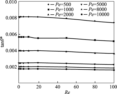
Fig. 6 Diffusion angle at different Reynolds numbers in concentration of 0.7
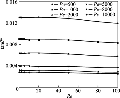
Fig. 7 Diffusion angle at different Reynolds numbers in concentration of 0.8
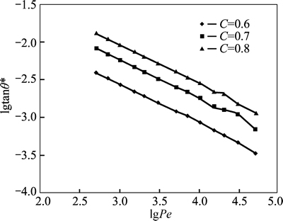
Fig. 8 Relationship between diffusion angle and Peclet number for water
Getting rid of the inflection points whose Peclet numbers are larger than 10000, the slopes at different relative concentrations differ slightly, namely �C0.504217 (C=0.6), �C0.506586 (C=0.7) and �C0.509944 (C=0.8), all of which are close to the theoretical value �C0.5. Accordingly, the simulation results are in good agreement with the theoretical value when the Peclet number is within the range of 0�C10000. As the linear relationship of C=0.6 is more stable and the slope is much closer to the theoretical value, the concentration of 0.6 is considered to be the best selection of the concentration boundary for diffusion.
4.2 Simulation results of other liquids
With in-depth exploration, the problem whether the conclusions for water are applicable for other liquids emerges to us. So, simulations of different kinds of fluids are conducted. It is worth mentioning that the liquids must have various diffusivities which cover a range of typical diffusivities of common liquids, therefore, glycerol and ionic liquids are chosen for the simulations.
The relationship between lgPe and lgtan��* at different concentrations for glycerine and ionic liquids are shown respectively in Fig. 9 and Fig. 10. Same trends are observed for both glycerol and ionic liquids, that is, lgtan��* is in a linear relationship with lgPe and inflection points appear when Peclet number increases to 15000 especially for C=0.7 and C=0.8.
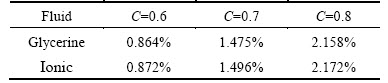
The slopes and relative errors for glycerine and ionic liquids at different concentration boundaries are listed in Table 3 and Table 4. It is apparent that the slopes for glycerine and ionic liquids both approach the theoretical value and the deviation is within the range of 0.864%�C2.172%. Due to the stability of linear relationship and less deviation of slope, the concentrationboundary of 0.6 is regarded as the best interface for calculation of the diffusion angle in experiments. As we known, Schmidt number (Sc) is the ratio of momentum diffusivity to mass diffusivity, which reflects the type of the diffusion fluids. Therefore, as the simulation results for other liquids (glycerine and ionic) are the same with water, the diffusion angle is also irrelative to Sc.
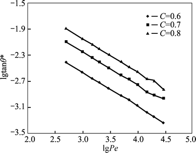
Fig. 9 Relationship between lgPe and lgtan��* at different concentrations for glycerine
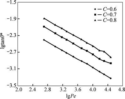
Fig. 10 Relationship between lgPe and lgtan��* at different concentrations for ionic
Table 3 Slopes for glycerine and ionic at different concentration boundaries
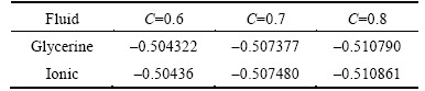
Table 4 Relative errors for glycerine and ionic at different concentration boundaries
5 Conclusions
1) The definition of ��diffusion angle�� is put forward by selecting a concentration interface as the specified edges of the angle. By theoretically deducting the linear relationship between the diffusion angle and Peclet number, it is found that the diffusion angle changes only with the Peclet number.
2) The simulation results reveal that the linear relationship between lgtan��*and lgPe is in a good agreement with the theoretical analysis. The slope deviations from the theoretical value are within 2.2%. And the simulation results also prove that the diffusion angle changes only with Pe, whilst it is irrelative to Re and Sc. The concentration of 0.6 is considered to be the best concentration boundary for calculation of the diffusion angle in the measurement experiments.
3) This work proves the feasibility of measuring the liquid diffusivity without disturbing the flow. However, to guarantee the accuracy of the measurement, experiments are suggested to be carried out at flow conditions of Re��10 and Pe��10000.
Acknowledgement
Many thanks are also given to the High Performance Computing Centre of Central South University, China, for the great support of computing resources.
References
[1] QUAKE S R, SCHERER A. From micro-to nanofabrication with soft materials [J]. Science, 2000, 290: 1536�C1540.
[2] ANDERSSON H, van den BERG A. Microfluidic devices for cellomics: A review [J]. Sensor Actuator B: Chemical, 2003, 92(3): 315�C325.
[3] EBRAHIMI S, HASANZADEH-BARFOROUSHI A, NEJAT A, KOWSARY F. Numerical study of mixing and heat transfer in mixed electroosmotic/pressure driven flow through T-shaped microchannels [J]. International Journal of Heat and Mass Transfer, 2014, 75(8): 565�C580.
[4] WANG Xiao-bo, YANG Jun, HUANG Ying. Cell separation by dielectrophoretic filed-flow-fractionation [J]. Anal Chem, 2002, 72(4): 832�C839.
[5] TALLAREK U, RAPP E, SCHEENEN T, BAYER G, van AS H. Electroosmotic and pressure-driven flow in open and packed capillaries: Velocity distributions and fluid dispersion [J]. Anal Chem, 2000, 72(10): 832�C839.
[6] CHIU D T , JEON N L, HUANG S, KANE R S, WARGO C J, CHOI I S, INGBER D E. Patterned deposition of cells and proteins onto surfaces by using three-dimensional microfluidic systems [J]. Proc Natl ACAD Sci USA, 2000, 97(6): 2408�C2413.
[7] LIN Ying, YU Yu, WANG Zhen-yu, TU Shan-tung, WANG Zheng-dong. Laminar flow diffusion interface control in a microchannel with accurate Raman measurement [J]. Chemical Engineering and Processing, 2012, 57/58: 1-7.
[8] SOLEYMANI A, KOLEHMAINEN E, TURUNEN I. Numerical and experimental investigations of liquid mixing in T-type micromixers [J]. Chemical Engineering Journal, 2008, 135: 219�C228.
[9] HSIEH S S, LIN J W, CHEN J H. Mixing efficiency of Y-type micromixers with different angles [J]. International Journal of Heat and Fluid Flow, 2013, 44(12): 130�C139.
[10] RAN Rui. Simulation and experimental research on microfluidic chip [D]. Shanghai: Chinese Academy of Sciences, 2006. (in Chinese)
[11] AFZAL A, KIM K Y. Flow and mixing analysis of non-Newtonian fluids in straight and serpentine microchannels [J]. Chemical Engineering Science, 2014, 116: 263�C274.
[12] WANG Rui-jin. Numerical simulation of transverse diffusion in a microchannel [J]. Journal of Hydrodynamics, 2004, 16(6): 651�C657.
[13] ZHANG Xin-feng. Study on flow and mixing technique in Microfluidic systems [D]. Hefei: University of Science and Technology of China, 2007. (in Chinese)
[14] GOBBY D, GAVRIILID A, ANGELI P. Mixing characteristics of T type microfluidic mixers [J]. Journal of Micromechanics and Microengineering, 2001, 11(2): 126�C132.
[15] ADEOSUN J T, LAWAL A. Numerical and experimental studies of mixing characteristics in a T-junction microchannel using residence- time distribution [J]. Chemical Engineering Science, 2009, 64(10): 2422�C2432.
[16] WANG Rui-jin. Research on the mechanism of diffusion and mixing in the micro-channel flow and micro-mixer [D]. Hangzhou: Zhejiang University, 2005. (in Chinese)
[17] ZHENG Yi. Study on the secondary flowing etching method inside microchannels based on the control of microscale laminar flow [D]. Hangzhou: Zhejiang University, 2010. (in Chinese)
(Edited by YANG Bing)
Foundation item: Project(51106184) supported by the National Natural Science Foundation of China
Received date: 2015-01-30; Accepted date: 2015-07-22
Corresponding author: CHEN Zhuo, Professor, PhD; Tel: +86�C13974891750; E-mail: chenzhuo@csu.edu.cn
Abstract: A CFD simulation was carried out to investigate the mixing process in a Y-shape micromixer with the software Fluent 6.3. The definition of the ��diffusion angle�� is proposed to describe the molecular diffusion process associated with the flow at low Reynolds number. The linear relationship between the diffusion angle and the Peclet number (Pe) is determined by both theoretical analysis and numerical simulation. Moreover, the simulation results reveal that the diffusion angle is only related to the Peclet number whilst it is irrelevant to the changes of Re (Reynolds number) and Sc (Schmidt number). The range of Peclet number and Reynolds number for experimental measurement are also suggested as Pe��10000 and Re��10.
