

Computation of deformation-induced textures in electrodeposited nickel coating
LONG Shi-guo(��ʿ��), ZHOU Yi-chun(���洺), PAN Yong(�� ��)
Key Laboratory for Advanced Materials and Rheological Properties of Ministry of Education,
Faculty of Material Photoelectron Physics, Xiangtan University, Xiangtan 411105, China
Received 8 April 2006; accepted 20 April 2006
Abstract:
The deformation-induced textures in electrodeposited nickel coating were numerically studied. The finite element method (FEM) for polycrystalline was developed based on Taylor model. Then the deformation-induced textures in electrodeposited nickel coating with initial random and lamellar texture were simulated under tensile load. It is found that the initial textures significantly influence the deformation-induced textures. For nickel coating with the initial random textures, when the tensile strain is about 40%, there are some lamellar textures. For nickel coating with the initial lamellar textures, the lamellar texture is more intensity with the increase of the tensile strain. With the increase of the tensile strain in the coating, there are more pronounced element distortion and a more inhomogeneous deformation. Due to the different crystal orientations, the grain-scale roughness is observed. With increasing tensile strain in the coating, the surface grain-scale roughness increases on the free surface. The surface roughness of the coating with initial random texture is lower than that with the initial lamellar texture.
Key words:
electrodeposited nickel coating; deformation-induced texture; Taylor model; FEM; polycrystalline;
1 Introduction
Surface modification by electrodeposited nickel coating is an important technology. The nickel coating is often electrodeposited on the steel substrate and its thickness is 1-20 ��m. The grain size is micrometer or nanometer[1-7]. With the development of this material, the process technique that the nickel is firstly electrodeposited on the steel substrate and then the coating and substrate are wholly formed is instead of the process technique that the steel is firstly formed and then the production surface is electrodeposited nickel coating. There are initial textures in the electrodeposited nickel coating and the deformation process will induce some new deformation-induced textures in the coating[8-10]. The deformation-induced textures in the coating more significantly influence the deformation performance of the electrodeposited nickel coating than that of bulk materials. Furthermore, the deformation-induced textures also influence the other performance of the coating, such as corrosion performance. The mechanism of the deformation- induced texture in nickel still has not been clearly elucidated. Therefore, it is necessary to study the deformation-induced textures in the electrodeposited nickel coating.
In this paper, the deformation-induced textures in electrodeposited nickel coating with the micrometer grain size were numerically studied. Firstly, the finite element method (FEM) for polycrystalline was developed based on Taylor model. Then the deformation-induced textures in electrodeposited nickel coating were simulated for different initial textures under tensile condition.
2 Simulation methods
Some polycrystalline models have been applied to predict the deformation texture and plastic anisotropy. The Taylor model is a rigid-plastic model assuming uniform plastic strain in each grain which has been used by many researchers[11]. Fig.1 shows the scheme of finite element polycrystalline model, which showing a polycrystalline aggregate, where each element represents a single crystal with cubic shape. The crystal orientation is assigned random or in some directions[12].
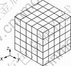
Fig.1 Scheme of finite-element polycrystal model
The slip systems of fcc structure are defined in Fig.2. For the fcc material, such as nickel, there are four slip plane and each slip plane has three slip directions in one grain.
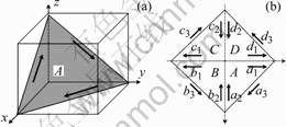
Fig.2 Scheme of slip system in of fcc structure: (a) One slipplane and its slip directions; (b) Whole slip planes and slip directions
Denote share strain increment on the ![]() th slip system by
th slip system by ![]() , unit normal vector on the slip plane by
, unit normal vector on the slip plane by ![]() and unit vector in the slip direction by
and unit vector in the slip direction by ![]() . Plastic strain increment of a crystal is represent by
. Plastic strain increment of a crystal is represent by
![]() (1)
(1)
where ![]() .
.
The share stress in a slip system is given by
![]() (2)
(2)
Denote critical yielding shear stress by![]() , and then we have the yielding condition for each slip system
, and then we have the yielding condition for each slip system
![]() (3)
(3)
where ![]() .
.
The first approximation is given by an elastic solution assuming ![]() at the beginning of each time step. If the shear stress exceeds the yielding stress, a small amount of slip may be accumulated on that slip system. Each crystal has some plastic strain increment, from which the virtual external forces
at the beginning of each time step. If the shear stress exceeds the yielding stress, a small amount of slip may be accumulated on that slip system. Each crystal has some plastic strain increment, from which the virtual external forces ![]() are evaluated and the FEM analysis is performed. Thus obtained plastic response might result in stress relaxation and the new shear stress may approach to the yielding stress. These processes are iterated until the accumulation of plastic strain ceases. The accumulation of slip on each slip system at the iteration step is given by
are evaluated and the FEM analysis is performed. Thus obtained plastic response might result in stress relaxation and the new shear stress may approach to the yielding stress. These processes are iterated until the accumulation of plastic strain ceases. The accumulation of slip on each slip system at the iteration step is given by
![]() (4)
(4)
where ![]() and
and ![]() ,
, ![]() is shear modulus and
is shear modulus and ![]() is the iteration step interval. On the way of iteration, the term
is the iteration step interval. On the way of iteration, the term ![]() can be either positive or negative, where
can be either positive or negative, where ![]() may change according to a hardening rule. The value of
may change according to a hardening rule. The value of ![]() is subjected to the accumulation condition, that is
is subjected to the accumulation condition, that is
If ![]() , set
, set ![]() (5)
(5)
This condition guarantees that ![]() converges to either a positive value or zero, which corresponds to active or nonactive slip system, respectively. Thus the successive accumulation method determines rate-independent slips uniquely without active-nonactive judgment in advance[12].
converges to either a positive value or zero, which corresponds to active or nonactive slip system, respectively. Thus the successive accumulation method determines rate-independent slips uniquely without active-nonactive judgment in advance[12].
The macroscopic coordinate ![]() is related to the microscopic coordinate
is related to the microscopic coordinate ![]() by the Euler angle
by the Euler angle ![]() as illustrated in Fig.3.
as illustrated in Fig.3.
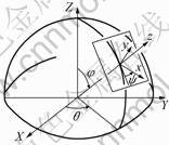
Fig.3 Scheme of Euler angle ![]()
The change of Euler angles due to deformation can be found as following[12],
 (6)
(6)
where ![]() is the lattice rotation.
is the lattice rotation.
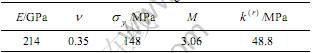
The coating under tension was simulated. The model is shown in Fig.4. The upper boundary of the coating is free and the bottom is given as the same strain of the substrate. For symmetry of the coating, only one quarter is simulated. The parameters of the coating are listed in Table 1[13].
In Table 1, M is the Taylor factor. It is assume that the grain size is 2 ��m and the thickness of the coating is 4 ��m.
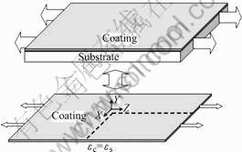
Fig.4 Model of nickel coating
Table 1 Parameters of nickel coating
3 Results and discussion
For the coating with random initial texture, the deformation of the coating under tensile load was simulated. Fig.5 shows the pole figure plots obtained from the above mentioned simulation method for tensile strain levels of 0, 0.20, 0.40 and 0.60.
The plots reveal the overall change in texture due to mechanical deformation under tensile mode. The initial coating(Fig.5(a)) displays a random texture. With the increase of strain in the coating, the directions of the
grains tend to the tensile direction(��=0) and the maximum shear direction(��=��/4). When the tensile strain is about 40%, there are some lamellar texture in the coating. In all plots, near perfect symmetry was observed.
Fig.6 shows the undeformed finite element mesh and deformed mesh of the coating with initial random texture after a tensile strain of 20%, 40% and 60%, respectively.
Fig.6 shows that with increase of the tensile strain in the coating, more pronounced element distortion and a more inhomogeneous deformation will come into being.
It is well known that surface roughening is a common phenomenon observed in plastically deformed polycrystalline metals. It is commonly accepted that this phenomenon originates in the heterogeneity of the polycrystalline material, whose grains have anisotropicelastic and plastic behavior and different crystal orientations[14]. For the electrodeposited nickel coating material, the surface roughness is important because it significantly affect the chemistry corrosion performance of the coating. Although the initial surface roughness of the coating is very low, the deformation can change the surface roughness. Therefore how the initial texture and the deformation level affect the surface roughness is very important for the nickel coating.
Fig.7 shows the surface topographies of the coating
with initial random texture before and after tensile deformation. In those figures, the values of x and z axis

Fig.5 Pole figures of deformation induced texture in coating with initial random texture: (a) ��=0; (b) ��=20%; (c) ��=40%;(d) ��=60%
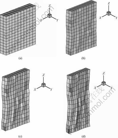
Fig.6 Undeformed finite element mesh and deformed mesh of coating with initial random texture under different tensile strain levels: (a) ��=0; (b) ��=20%; (c) ��=40%; (d) ��=60%
mean the location of the surface and that of y axis means the surface height. Before deformation of the coating, the surface is smooth. With the increase of strai, the surface roughness increases.
From Fig.7, the grain-scale roughness can be observed. The different crystal orientations lead to incompatibilities of deformation arising from the interactions between neighboring grains. At the free surface, these incompatibilities do not arise, which results in differential deformations in the normal to the surface and therefore, in grain-scale roughness.
In the following, the tensile deformation of the coating with initial lamellar texture was simulated and the result was compared with the deformation of the coating with initial random texture.
Fig.8 shows the pole figure plots of the coating with initial lamellar texture obtained for tensile strain levels of 0, 0.20, 0.40 and 0.60. The initial coating, Fig.8(a), displayed a lamellar texture. With the increase of the tensile strain in the coating, the lamellar texture in the coating is become more intensity. Compare the results of Fig.5 and Fig.8, it is found that the initial texture in the coating is significantly effect the deformation-induced texture in the coating.
Fig.9 shows the undeformed finite element mesh and deformed mesh of the coating with initial lamellar texture after a tensile strain of 20%, 40% and 60%.
Fig.9 shows that with the increase of the tensile strain in the coating, more pronounced element distortion and a more inhomogeneous deformation will come into being. Compare the results of Figs.6 and 9, it is found that the element distortion and inhomogeneous deformation of the coating with initial random texture is more significant than that with the initial lamellar texture.
Fig.10 shows the surface topographies of the coating with initial lamellar texture before and after tensile deformation. With the increase of the tensile
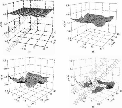
Fig.7 Surface roughness of coating with initial random texture: (a) ��=0; (b) ��=20%; (c) ��=40%; (d) ��=60%
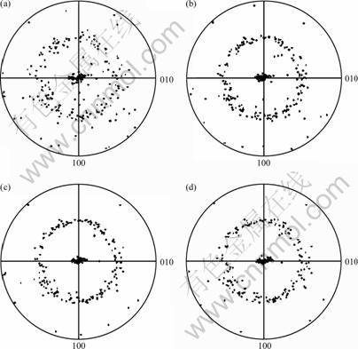
Fig.8 Pole figures of deformation induced texture in coating with initial lamellar texture: (a) ��=0; (b) ��=20%; (c) ��=40%;
(d) ��=60%
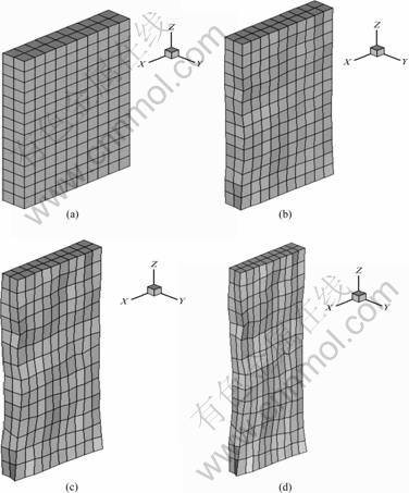
Fig.9 Deformation of coating with initial lamellar texture: (a) ��=0; (b) ��=20%; (c) ��=40%; (d) ��=60%

Fig.10 Surface roughness of coating with initial lamellar texture: (a) ��=0; (b) ��=20%; (c) ��=40%; (d) ��=60%
strain in the coating, the surface roughness increases. Compare the results of Figs.7 and 10, it is found that the surface roughness of the coating with initial random texture is lower than that with the initial lamellar texture. 4 Conclusions
The deformation-induced textures in electrodepo-
sited nickel coating were numerically studied. It is found that the initial textures significantly influence the deformation-induced textures. For nickel coating with the initial random textures, there are some lamellar textures when the tensile strain is about 40%. For nickel coating with the initial lamellar textures, with the increase of strain in the coating, the lamellar texture is more intensity. With the increase of the tensile strain in the coating, there are more pronounced element distortion and a more inhomogeneous deformation. Due to the different crystal orientations, the grain-scale roughness is observed. With the increase of the tensile strain in the coating, the surface grain-scale roughness increases. The surface roughness of the coating with initial random texture is lower than that with the initial lamellar texture.
References
[1] TUCK J R, KORSUNSKY A M, DAVIDSON R I. Modeling of the hardness of electroplated nickel coatings on copper substrates [J]. Surface and Coatings Technology, 2000, 127: 1-8.
[2] BASROUR S, ROBERT L. X-ray characterization of residual stresses in electroplated nickel used in LIGA technique [J]. Mater Sci Eng A, 2000, A288: 270-274.
[3] TJONG S C, CHEN H. Nanocrystalline materials and coatings [J]. Mater Sci Eng R, 2004, R45: 1-88.
[4] BUDROVIC Z, SWYGENHOVEN H V. Plastic deformation with reversible peak broadening in nanocrystalline nickel [J]. Science, 2004, 304: 9-11.
[5] JOSELL D, BWYGENHOVEN J E, SHAO I. Measuring the interface stress: silver/nickel interfaces [J]. Journal of Material Research, 1999, 14: 4358-4365.
[6] MCADDEN S X, MISHRA R S, VALIEV R Z. Low-temperature superplasticity in nanostructured nickel and metal alloys [J]. Nature, 1999, 398: 684-686.
[7] BASROUR S, ROBERT L, DELOBELLE P. Measurement of residual stresses in a plate using bulging test and a dynamic technique: application to electroplated nickel coatings [J]. Mater Sci Eng A, 2000, A288: 160-163.
[8] ZHOU L Q, ZHOU Y C, PAN Y. Coating thickness variation during multistep drawing processes [J]. Journal of Materials Science Letter, 2004, 39: 757-760.
[9] ZHOU L Q, ZHOU Y C, PAN Y. Pact performance of electrodeposited nickel coating on steel substrate [J]. Journal of Materials Science Letter, 2004, 39: 753-755.
[10] DAI C Y, PAN Y, ZHOU Y C. The effect of prepared parameters on the microstructure of electrodeposited nanocrystalline nickel coating [J]. Surface Review and Letters, 2004, 11: 433-442.
[11] TAKAHASHI H, MOTOHASHI H, TSUCHIDA S. Development of plastic anisotropy in rolled aluminium sheets [J]. International of Plasticity, 1996, 12: 935-949.
[12] TAKAHASHI H, MOTOHASHI H, TOKUDA M, ABE T. Elastic-plastic finite element polycrystal model [J]. International of Plasticity, 1994, 10: 63-80.
[13] DAO M, GU P, MAEWAL A, ASARO R J. A micromechanical study of residual stresses in functionally graded materials [J]. Acta Materialia, 1997, 45: 3265-3276.
[14] ZHAO Z, RADOVITZKY R, CUITINO A. A study of surface roughening in fcc metals using direct numerical simulation [J]. Acta Materialia, 2004, 52: 5791-5804.
Foundation item: Project(104014) supported by Fok Ying Tong Education Foundation; Project(05B008) supported by Scientific Research Fund of Education Department of Hunan Province, China
Corresponding author: LONG Shi-guo; Tel: +86-732-8293577; E-mail: longsg@xtu.edu.cn
