
Trans. Nonferrous Met. Soc. China 24(2014) 2650-2659
Experimental and CFD studies of solid-liquid slurry tank stirred with an improved Intermig impeller
Hong-liang ZHAO1, Zi-mu ZHANG1, Ting-an ZHANG1, Yan LIU1, Song-qing GU1, Chao ZHANG2
1. Key Laboratory of Ecological Utilization of Multi-metal Intergrown Ores of Ministry of Education, School of Materials and Metallurgy, Northeastern University, Shenyang 110819, China;
2. Shenyang Aluminum & Magnesium Engineering & Research Institute, Shenyang 110001, China
Received 5 September 2013; accepted 27 November 2013
Abstract:
The improved Intermig impeller has been used in the seed precipitation tank in China, which could enhance the mixing and suspension of Al(OH)3 particles and the power consumption declined largely. The flow field, solids hold-up, cloud height, just off-bottom speed and power consumptions were investigated in solid-liquid mixing system with this new type of impeller by CFD and water experiment methods. Compared with the standard Intermig impeller, the improved one coupled with specially sloped baffles could promote the fluid circulation, create better solids suspension and consume less power. Besides lower impeller off-bottom clearance is good for solid suspension and distribution. The just-off-bottom speed was also determined by a power number criterion. Meanwhile, the predicted results were in good agreement with the experimental data.
Key words:
CFD; stirred tank; solids suspension; mixing; improved Intermig impeller;
1 Introduction
In industrial processes, various solid-liquid multiphase flows have been intensively applied, such as catalysis reactions, crystallization, dissolution, polymerization. And one important aspect regarding the solids suspension and distribution was largely determined by types and structures of the impeller. As a low-shear axial flow agitator, the Intermig impeller has been widely utilized in solid-liquid suspensions, liquid-liquid dispersion, gas-liquid dispersion and heat transfer process, especially, at large diameter ratios (0.5T-0.95T) and Reynolds numbers (Re)>100 [1].
The seed precipitation step was one of the key steps in the Bayer process for the production of alumina, and it has great influence on alumina product��s outputs and quality and also has indirect effect on other procedures [2,3]. In 2000, the Intermig impeller was improved (see in Fig. 1) by Shenyang Aluminum & Magnesium Engineering & Research Institute (SAMI) of China for seed precipitation tank with very high solids content (800 g/L). Compared with the pitched blade agitators, the improved Intermig impeller coupled with two special sloped baffles could enhance the effect on Al(OH)3 particles mixing and suspension and power consumption declined largely [4]. Especially, the deposition of Al(OH)3 particles was greatly improved at the tank bottom. It appears that the improved Intermig impeller has good performance for high solid content system. By now, many researches [5,6] about seed precipitation process have been reported, but few researches were focused on the flow field in the seed precipitation tank, except the air-agitated one [7]. Moreover, many investigations [8,9] were focused on mixing performance of standard Intermig impeller mainly, but few of them were applied to investigating the solid-liquid slurry flows.
In addition, many researchers have focused their attention on the simulation and experiment of solid particles suspension and distribution in liquid-solid stirred vessels in recent years. TAMBURINI et al [10] numerically simulated the case of a dense solid-liquid suspension in a baffled tank stirred by a Rushton turbine. The fraction of suspended particles has been predicted at the rotational speed lower than Njs by the double Eulerain multi fluid model coupled with a standard k-�� turbulence model and the MRF approach. The simulated results were well validated by the experiments. His another work [11] focused on the prediction of the amount of suspended particles at agitation speeds encompassing both the filleting and the complete suspension regime, and the suspension curves of solid particles were obtained. WADNERKAR et al [12] used the modified drag law to simulate low solids hold-up in stirred tank. The predictions in terms of velocity profiles and the solids distribution were found to be in reasonable agreement with the literature experimental data. FENG et al [13] used a two-phase explicit algebraic stress model to simulate solid�Cliquid turbulent flow in a stirred tank equipped with a Rushton turbine. The predicted velocity components, turbulent quantities and solid concentration are in good agreement with the reported experimental data. MONTANTE et al [14] experimentally investigated the dilute suspensions of solid particles in the tank stirred with a Rushton turbine, and the liquid flow field and solid-liquid slip velocity were measured by particle image velocimetry method.
In this work, more attention was taken to analyze the mixing performance of this new type of impeller, improved Intermig impeller in high solid content mixing system. Both computational and experimental analyses were performed in a baffled tank stirred with an improved Intermig impeller. Three-dimensional multiphase turbulence flow was simulated by adopting Eulerian multiphase model coupled with the standard k-�� turbulence model. An unsteady sliding mesh approach was used to model the impeller rotation. Meanwhile, the solid concentration was also measured by a PC6D fiber optic reflection probe under the same conditions. The model predictions were compared with the experimental data of solid concentration profile and power consumption.
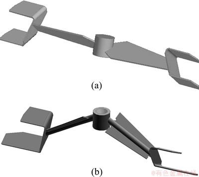
Fig. 1 Structures of standard (a) and improved (b) impeller
2 Experimental
2.1 Improved Intermig impeller
Figure 1 shows the structures of the standard and improved impellers, respectively. Both of the impellers are composed of the inner blades of single layer and the external blades of two layers. The differences of the improved one are that the inner blade has 30�� downward and the external blade of lower layer is lengthened. In this study, two impellers were positioned at a same ratio of impeller and tank diameter (D/T=0.624).
2.2 Experimental installation
Figure 2 shows the experimental installation which consists of a console desk, stirring apparatus, a flat- bottomed baffled tank (diameter T=0.425 m; liquid height H=0.4 m) and the impeller. Console desk could control the height, rotational direction and speed of the impeller.

Fig. 2 Experimental installation and cover with measuring holes
The tank made of plexiglass was set on a iron stand that was convenient for observing the solids suspension on the tank bottom. Two special baffles in width of 0.1T were mounted perpendicular to the tank wall and had a slope with an angle of 120�� on the bottom of them. A cover with measuring holes was on the top of the tank. The shaft and impeller were made of stainless steel. The ratio of impeller off-bottom clearance to tank diameter (C/T) was from 0.024 to 0.165, and the impeller rotational speed was from 150 to 330 r/min. Water and glass particles were used as liquid and solid phases respectively. The solid hold-up was set at ��av=0.323 (800 g/L). The model dimensions and material properties are listed in Table 1.
Table 1 Model dimensions and material properties

The torques and rotational speeds were recorded with a torque sensor mounted on the shaft. And the power consumptions could be calculated by
P=M��=2��NM/60 (1)
The power consumption with each condition was measured repeatedly, then the average value could be obtained and the relative error was less than 5%.
2.3 Solids concentration measurement
The profile of local solid concentration in the water-glass mixing system was measured by using a PC6D fiber optic reflection probe (manufactured by Institute of Process Engineering, Chinese Academy of Sciences).
SHAN et al [15] used this probe to study the solid concentration profile in an unbaffled stirred tank, and an accuracy of 0.5% for the concentration measurement was observed. The measuring principle was that a beam of measuring light is sent out from the probe to the fluid and the intensity of reflected light is linearly proportional to the solid concentration. Then the photoelectric sensor receives the reflected light and converts it into voltage signal. The calibrating curve of solid concentration and voltage is shown in Fig. 3. Moreover, the value of solid concentration can be calculated by the following equation:
 (2)
(2)
3 Computational model
3.1 Model equations
The numerical simulations of the stirred tank were performed by adopting Eulerian granular multiphase (EGM) model and standard k-�� turbulence model [16]. And the mass transfer, lift force and virtual mass force were not considered.

Fig. 3 Relationship between voltage and solid concentration
The governing equations pertaining to the continuous phase of liquid are given as
 (3)
(3)

 (4)
(4)
The governing equations pertaining to the suspended phase of solid particles are given as
 (5)
(5)

 (6)
(6)
where  is the phase stress-strain tensor which is contributed by viscosity and Reynolds stress:
 (7)
(7)
And in each calculated cell the volume fractions of liquid phase and solid phase are computed based on the following constraint:
 (8)
(8)
The Gidaspow model [17] combining with the WEN and YU model and the Ergun equation is usually used to calculate the momentum exchange coefficient in high solid hold-up system.
When ��l>0.8, the liquid-solid exchange coefficient Kls is in the following form:
 (9)
(9)
where CD is the drag coefficient computed by
 (10)
(10)
where Res is the relative Reynolds number computed by
 (11)
(11)
When ��l<0.8, Kls is in the following form:
 (12)
(12)
The mixture standard k-�� turbulence model was adopted in this simulation, in which both solid and liquid phases were assumed to share the same values of k and ��. The governing equations for turbulent kinetic energy, k, and turbulent energy dissipation rate, ��, are listed below:

 (13)
(13)

 (14)
(14)
where the mixture density �� and velocity v are computed by
 (15)
(15)
and
 (16)
(16)
And the turbulent viscosity ��t is computed by
 (17)
(17)
And Gl,s is the generation of turbulence kinetic energy due to the mean velocity gradients and it is calculated as
 (18)
(18)
The standard set of parameters usually adopted for the k-�� model is used in all of the computations, namely:
C��=0.09, C1=1.44, C2=1.92, ��k=1.0, ��z=1.3.
3.2 Solution domain and boundary condition
The simulations kept the same conditions as the experiment and the model dimensions and material properties are shown in Table 1. In the computational model, standard wall functions were used on all solid walls and the thickness of baffles was ignored. The impeller was represented by an unsteady sliding mesh approach [18]. The SIMPLE algorithm was adopted for couple pressure and velocity, and the second-upwind discretization scheme was used for governing equations. The computational results were considered converged when all the residuals are less than 10-4.
Hybrid meshes are generated in the whole solution domain and the meshes are locally refined in rotational domain and around the baffles. The mesh models of the impeller and the baffled tank are shown in Figs. 4 and 5, respectively.

Fig. 4 Mesh of improved Intermig impeller
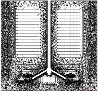
Fig. 5 Mesh of baffled stirred tank
4 Results and discussion
4.1 Influence of grid size
In this study, three grid sizes of 260000, 390000 and 520000 were considered to investigate the effect of grid size on velocity and solids hold-up distribution under the conditions of C/T=0.071, D/T=0.624, N=250 r/min. The predicted results using different grids are listed in Figs. 6 and 7, respectively. The differences of velocity and solid hold-up distributions in the axial and radial directions were found to be very small (~5%). Based on these results, all the subsequent simulations were carried out with about 260000 computational cells.

Fig. 6 Velocity distribution at different grid sizes
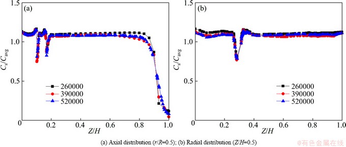
Fig. 7 Solid hold-up distribution at different grid sizes
4.2 Comparison between standard and improved Intermig impellers
The differences of flow field and solids hold, up distribution are numerically compared between the tank stirred with an improved Intermig impeller and two special sloped baffles and the system installed with a standard Intermig impeller and 4 vertical baffles under the same conditions of N=250 r/min, C/T=0.024 and D/T=0.624.
The solid volume fraction distribution on the tank bottom is shown in Fig. 8. The solid hold-up near the wall and at the center of tank bottom is larger than that of other place where is well stirred. Especially, a large number of solids settled at the center of tank bottom using the standard Intermig impeller, where may easily cause the solid deposition. In contrast, the solids distribute more uniform at the whole bottom, which indicates that the improved Intermig impeller is better for solid suspension.
Figure 9 shows the velocity vector distribution between the standard and improved Intermig impeller. Under the interaction between the baffles and impeller, secondary circulation loops are generated. It is apparent that the improved one coupled with sloped baffles provides a stronger axial circulation and more power for solid suspension. When the improved Intermig impeller rotates in clockwise direction, the external blades exert a force inclined downwards on the fluid flow and the baffles with a slope change particles motion into the upward direction. So subjected to the interactions between the baffles and impeller, the stronger secondary circulation loops can provide more kinetic energy for solid suspension. Moreover, the power consumption of standard and improved Intermig impellers is 40.6 W and 31.7 W respectively. Therefore, compared with the standard Intermig impeller and vertical baffles, the improved one coupled with sloped baffles can not only enhance solid suspension, but also promote circulation loops for mixing. Above all, more than 20% of the power consumption is saved.
4.3 Computational velocity field
Figure 10 shows the two-dimensional velocity vector at a rotational speed of 250 r/min with different impeller off-bottom clearances (C/T=0.024-0.165). It can be seen from flow patterns that the strong secondary circulation loop flow with higher velocity generates between the impeller and baffles, and then spreads to the upper part of the tank. At lower impeller off-bottom clearance, due to the strong action between the impeller and the slopes, the fluid can be pumped to higher place. When C/T=0.024, the secondary loop develops sufficiently and the circulating flow can reach the liquid surface. On the contrary, when increasing C/T to 0.165, the interaction between the impeller and baffles is weakened. The secondary circulation loops can not reach the top of the liquids, where there is no enough kinetic energy to maintain the solid particles in suspension.

Fig. 8 Simulated solid volume fraction distribution on tank bottom

Fig. 9 Velocity vector between impeller and baffles
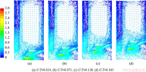
Fig. 10 Liquid phase flow pattern for N=250 r/min
4.4 Solids hold-up distribution
Figure 11 shows the solids volume fraction distribution under the conditions of a rotational speed of 250 r/min and C/T from 0.024 to 0.165. The flow profiles show that the angle of discharge (with reference to the vertical) increases with an increase in the clearance, and this explains the increased solid accumulation with an increase in the impeller clearance. On one hand, a low clearance causes the turbulence decaying less. On the other hand, the interaction between the impeller and baffles is enhanced at a low clearance. So the solid particles can be pumped to the higher place at lower clearance (C/T=0.024) and distribute uniformly and few clear liquid regions exist.
When increasing the C/T to 0.118, the solid particles accumulate around the center of the bottom, besides the clear liquid layer increasing. With a further increase in C/T, the decreasing energy for suspension of lower solid and the weakening interaction between the impeller and baffles are responsible for the solid accumulation at the center and along the periphery of the tank bottom. Compared with the conditions of C/T=0.118 and 0.165, the clear liquid layer does not change too much which agrees with the results of flow pattern shown in Fig. 10.

Fig. 11 Simulated solid volume fraction distribution for N=250 r/min
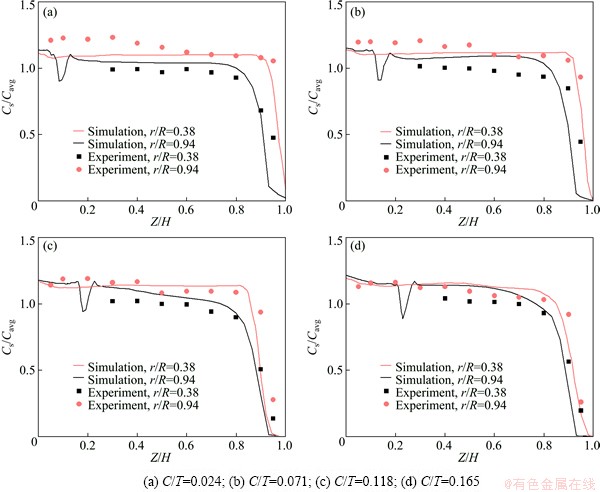
Fig. 12 Comparison of axial and radial solid concentration profiles for N=250 r/min
Figure 12 shows the solid concentration profile in axial and radial directions at the same conditions of Fig. 11. The radial positions of measuring points were selected near shaft and baffles, and the axial positions were from the tank bottom to the liquid surface. From the simulated and experimental results, the solid concentration is a little bit lower near the shaft than that close to the baffles, which is caused by the centrifugal force of a rotating impeller. At the same impeller off-bottom clearance, the height of clear liquid (Cs/Cavg<1) is also larger under the condition of r/R=0.38 than that under r/R=0.94. In contrast, when increasing the C/T, the solid concentration changes more under the condition of r/R=0.94. The difference of solid concentration between the two radial positions becomes smaller at a higher C/T. It is necessary to point out that the solid concentration in axial has an extreme at r/R=0.38, which is due to less solid distribution around the impeller discharge zone.
4.5 Cloud height
The solid cloud heights with different N and C/T were measured in the experiment and simulation, respectively. The experimental values of Hc were determined visually from outside the tank by measuring the distance between the tank bottom and the cloud surface. The cloud height in numerical simulation was defined as the maximum axial height of an iso-surface of solid phase volume fraction. KASAT et al [19] proposed a criterion of the iso-surface defined as the average solid phase volume fraction.
Figure 13 shows the experimental and simulated results of cloud height with different N (200-250 r/min) and C/T (0.024-0.165). The real lines indicate the simulated results and the dotted lines indicate the experimental results. It is easy to draw that higher rotational speed provides more kinetic energy for solid suspending, so the cloud height increases with the increasing of N. While the cloud height shows a declined tendency with the increasing of C/T. The interaction between the baffles and impeller is stronger at lower C/T, which can enhance the solid suspension, thereby the cloud height tends to be higher.

Fig. 13 Cloud height with different C/T and N
4.6 Power number and just-off-bottom speed
Figure 14 shows the simulated and experimental power numbers at different rotational speeds under the condition of C/T=0.024. The range of power number computed is from 0.3 to 0.25, which is 5% lower than the experimental results, which may be caused by mechanical loss in the experiments. With the increase of N, the power number decreases rapidly at first, and then tends to be stable. At low impeller speeds, vast deposition of solid particles causes the formation of fillets at the center and along the periphery of the tank bottom, it streamlines the flow pattern on the tank bottom. Due to the ��false bottom effect��, the impeller pumping action is reduced, which causes the decrease of power number. More solid particles suspend with the further increasing of impeller rotational speed. When close to the just-off-bottom speed, almost all the particles are suspended, and the power number changes slightly. This criterion of power number for determining the Njs has been reported by KASAT et al [20]. The value of Njs determined by power number criterion is equal to ~240 r/min, which shows good agreement with the result determined visually (all the solid particles remained stationary at the bottom for less than 1-2 s).
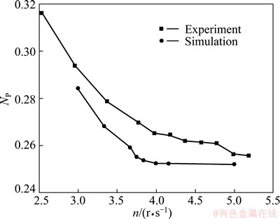
Fig. 14 Experimental and simulated power number for C/T=0.024
5 Conclusions
1) Compared with the standard Intermig impeller, the improved one coupled with the special baffles sloped can promote good circulation in axial, which improves the suspension of solid particles on the tank bottom. Lower impeller off-bottom clearance is better for enhancing the distribution of secondary loop flow for the upper fluid.
2) The computational model predicted the solid concentration distribution that the mixing effect decreases with an increase in impeller off-bottom clearance, there by the cloud height also increases. The computational results show good agreement with the experimental results.
3) The power number decreases with increasing the rotational speed and impeller off-bottom clearance. The range of power number computed is from 0.3 to 0.25, which is ~5% lower than the experimental result. And the Njs determined by power number criterion is equal to 240 r/min under condition of D/T=0.624 and C/T=0.024, which shows good agreement with the determined visually.
Nomenclatures
C
Impeller off-bottom clearance, mm;
CD
Drag coefficient in turbulent liquid;
C1, 2, ��
Coefficients of turbulent model;
Cs
Solid particle concentration, g/L;
Cavg
Average solid particle concentration, g/L;
ds
Particle diameter, m;
D
Impeller diameter, m;
Fl, s
Force, N;
g
Gravity acceleration, m/s2;
G
Turbulence generation, kg��m/s3;
H
Liquid height, m;
Hc
Cloud height, m;
I
Unit tensor;
k
Turbulent kinetic energy, m2/s2;
Kls, sl
Fluid-solid exchange coefficient;
M
Torque, N��m;
n
Impeller rotational speed, r/s;
N
Impeller rotational speed, r/min;
Njs
Just-off-bottom speed, r/min;
NP
Power number;
p
Pressure, Pa;
P
Power consumption, W;
r
Radial distance between measuring point and shaft, m;
R
Tank radius, m;
Res
Relative Reynolds number;
t
Time, s;
T
Tank diameter, m;
v
Velocity, m/s;
V
Voltage, V;
Wb
Baffle width, m;
Z
Axial distance between measuring point and tank bottom, m;
��
Volume fraction;
��
Turbulent kinetic energy dissipation rate, m2/s3;
��
Viscosity, kg/(m��s);
��
Density, kg/m3;
��k, ��
Standard coefficients for k-�� turbulence model;
��
Shear stress, N/m2;
��
Angular velocity, rad/s.
Subscripts
avg
Average;
l
Liquid;
s
Solid particle;
t
Turbulent.
References
[1] EKATO. Handbook of mixing technology: General theory, selection criteria, application [M]. Schopfheim: EKATO R��hr-und Mischtechnik GmbH, 1991.
[2] LI X B, YAN L, ZHOU Q S, LIU G H, PENG Z H. Thermodynamic model for equilibrium solubility of gibbsite in concentrated NaOH solutions [J]. Transactions of Nonferrous Metals Society of China, 2012, 22(2): 266-270.
[3] LI X B, YAN L, ZHAO D F, ZHOU Q S, LIU G H, PENG Z H, YANG S S, QI T G. Relationship between Al(OH)3 solubility and particle size in synthetic Bayer liquors [J]. Transactions of Nonferrous Metals Society of China, 2013, 23(5): 1472-1479.
[4] ZHANG Ting-song, ZHANG Chao, WANG Yong-cai, DONG Yi-min, ZHANG De-ren. A type of impellers for seed precipitation agitated tank: China, ZL200520145940.6 [P]. 2006-12-20. (in Chinese)
[5] LU B L, CHEN Q Y, YIN Z L, HU H P. Effects of Na(4)EDTA and EDTA on seeded precipitation of sodium aluminate solution [J]. Transactions of Nonferrous Metals Society of China, 2010, 20(S1): s37-s40.
[6] WU Y S, ZHANG D, LI M C, BI S W, YANG Y H. Periodical attenuation of Al(OH)3 particles from seed precipitation in seeded sodium aluminate solution [J]. Transactions of Nonferrous Metals Society of China, 2010, 20(3): 528-532.
[7] CHEN Q P, YAN H J, GE S H, ZHOU J M. Experimental verification of mathematical model for multiphase flow in air-agitated seed precipitation tank [J]. Transactions of Nonferrous Metals Society of China, 2011, 21(7): 1680-1684.
[8] SZALAI E S, ARRATIA P, JOHNSON K, MUZZIO F J. Mixing analysis in a tank stirred with Ekato Intermig impellers [J]. Chemical Engineering Science, 2004, 59(18): 3793-3805.
[9] AUBIN J, XUEREB C. Design of multiple impeller stirred tanks for the mixing of highly viscous fluids using CFD [J]. Chemical Engineering Science, 2006, 61(9): 2913-2920.
[10] TAMBURINI A, CIPOLLINA A, MICALE G. CFD simulation of solid liquid suspensions in baffled stirred vessels below complete suspension speed [J]. Chemical Engineering Transactions, 2011, 24: 1435-1440.
[11] TAMBURINI A, CIPOLLINA A, MICALE G, BRUCATO A, CIOFALO M. CFD simulations of dense solid-liquid suspensions in baffled stirred tanks: Prediction of suspension curves [J]. Chemical Engineering Journal, 2011, 178(15): 324-341.
[12] WADNERKAR D, UTIKAR R P, TADE M O, PAREEK V K. CFD simulation of solid-liquid stirred tanks [J]. Advanced Powder Technology, 2012, 23(4): 445-453.
[13] FENG X, LI X Y, CHENG J C, YANG C, MAO Z S. Numerical simulation of solid�Cliquid turbulent flow in a stirred tank with a two-phase explicit algebraic stress model [J]. Chemical Engineering Science, 2012, 82(12): 272-284.
[14] MONTANTE G, PAGLIANTI A, MAGELLI F. Analysis of dilute solid-liquid suspensions in turbulent stirred tanks [J]. Chemical Engineering Research and Design, 2012, 90(10): 1448-1456.
[15] SHAN X G, YU G Z, YANG C, MAO Z S, ZHANG W G. Numerical simulation of liquid-solid flow in an unbaffled stirred tank with a pitched-blade turbine downflow [J]. Industrial and Engineering Chemistry Research, 2008, 47(9): 2926-2940.
[16] CAO X C, ZHANG T A, ZHAO Q Y. Computational simulation of fluid dynamics in a tubular stirred reactor [J]. Transactions of Nonferrous Metals Society of China, 2009, 19(2): 489-495.
[17] ANSYS Inc. ANSYS FLUENT 12.0 Theory Guide [M]. 2009.
[18] BAKKER A, LAROCHE R D, WANG M H, CALABRESE R V. Sliding mesh simulation of laminar flow in stirred reactors [J]. Chemical Engineering Research and Design, 1997, 75(1): 42-44.
[19] KASAT, G R, KHOPKAR, A R, PANDIT, A B, RANADE V V. CFD simulation of liquid-phase mixing in solid-liquid stirred reactor [J]. Chemical Engineering Science, 2008, 63(15): 3877-3885.
[20] KASAT G R, PANDIT A B. Review on mixing characteristics in solid-liquid and solid-liquid-gas reactor vessels [J]. The Canadian Journal of Chemical Engineering, 2005, 83(4): 618-643.
�Ľ�Intermig����Һ��̬����۵�ʵ���CFD�о�
�Ժ���1������ľ1����͢��1���� ��1��������1���� ��2
1. ������ѧ ������ұ��ѧԺ���������������̬�����ý������ص�ʵ���ң����� 110819��
2. ������þ����о�Ժ������ 110001
ժ Ҫ���Ľ�Intermig���Ѿ���Ӧ�õ����ڵ��ַ��豸�У����ڴٽ��������������������ͻ�ϵ�ͬʱ�����蹦��Ҳ�õ�����Ƚ��͡����ü���������ѧ��ˮģ��ʵ�����ϵķ����о��Ľ�Intermig����Һ������ϵ�е��������̺����Ƹ߶ȡ��ٽ�����ת���Լ�������������������Intermig����ȣ��Ľ����Intermig�������˲���ѭ�����ķ�չ���ٽ��˿�������������������Ҳ�õ����Ƚ��͡���Ҷ��ؾ���Խ��Խ�����ڿ������������ɢ�������ù����оݵõ��˿����������ٽ����ת�٣�ͬʱ������ֵģ��Ԥ��Ľ����ʵ�����ǺϽϺá�
�ؼ��ʣ�����������ѧ������ۣ�������������ϣ��Ľ�Intermig��
(Edited by Hua YANG)
Foundation item: Projects (50974035, 51074047) supported by the National Natural Science Foundation of China; Project (2010AA03A405) supported by the High-tech Research and Development Program of China
Corresponding author: Ting-an ZHANG; Tel: +86-24-83687715; E-mail: zta2000@163.net
DOI: 10.1016/S1003-6326(14)63395-1
Abstract: The improved Intermig impeller has been used in the seed precipitation tank in China, which could enhance the mixing and suspension of Al(OH)3 particles and the power consumption declined largely. The flow field, solids hold-up, cloud height, just off-bottom speed and power consumptions were investigated in solid-liquid mixing system with this new type of impeller by CFD and water experiment methods. Compared with the standard Intermig impeller, the improved one coupled with specially sloped baffles could promote the fluid circulation, create better solids suspension and consume less power. Besides lower impeller off-bottom clearance is good for solid suspension and distribution. The just-off-bottom speed was also determined by a power number criterion. Meanwhile, the predicted results were in good agreement with the experimental data.
