
J. Cent. South Univ. Technol. (2009) 16: 0653-0657
DOI: 10.1007/s11771-009-0108-1
![]()
Estimation of compaction grouting pressure in strain softening soils
YANG Xiao-li(����), ZOU Jin-feng(���)
(School of Civil and Architectural Engineering, Central South University, Changsha 410075, China)
Abstract:
A new method was proposed to predict the limited compaction grouting pressure for the soft soils. Theoretical basis of the method considered the conical shear failure above the grout bulb. Using the Mohr-Coulomb yield criterion as the initial yield function, the limited compaction grouting pressure was determined, according to the softening elastic-plastic model based on the conventional triaxial compression tests to simulate the strain softening soils. The small strain in the elastic zone and large stain in the plastic zone and the rational yield function for the strain softening phase stage, the analytical solutions to the compaction grouting pressure were presented. The results indicate reasonable agreement and show a good potential of the proposed method for rationally optimizing the design of compaction grouting operations.
Key words:
compaction grouting; strain softening; spherical cavity expansion; ultimate pressure��
1 Introduction
Compaction grouting is an important soil improvement and underpinning technique that involves injection of a very stiff grout material into the soil. The intention is to displace and compact the surrounding soil without permeating or hydro-fracturing it. A primary use of compaction grouting has been compacted with loose fills or natural loose soils, underpin structures that have suffered from differential settlement, and lift the structure, foundation, and subgrade to level [1-2]. Compaction grouting involves a set of complex parameters due to different possible soil conditions as well as grouting variables, e.g., grouting hole spacing, grouting stage length, injection rate, limiting injection pressure, and injection pipe diameter. The application of the method, however, relies greatly on practical experience and empiricism. A mechanistic model that rationally considers different variables involved in the process and allows for optimized design is not available, saying nothing of the analysis solution of the ultimate pressure, especially in the strain softening soil. Considering the above reasons, a theoretical model was presented to give the analysis solution for the compaction grouting pressure in strain softening soil. The model draws its theoretical basis from the two theories of cavity expansion and conical shear failure and combines them in a clear methodology for design purposes. The results have an important academic signification and application value.
2 Theoretical model
Based on the previous observations [3-5] and author��s works [6-8], the injection process comprises the following mechanisms.
2.1 Constitutive relationship
The tri-linear elastic-plastic model based on the conventional tri-axial compression tests was used to simulate the stress��strain curve for the strain softening soils [9-10]. The stress��strain curve of the conventional tri-axial compression tests is shown in Fig.1(a), and its simplification is shown in Fig.1(b).
In Fig.1, ��1 is the major principal strain; ��1 and ��3 are the major principal stress and the minor principal stress, respectively; ��cr is the residual strength; ��c is the compressive strength; ��r is the radial strain; �� is the factor corresponding to elastic major strain ![]() . Under the action of the surrounding pressure, in order to simplify the analysis, it is assumed that the soil is regarded as a linearly elastic solid before its strength reaches the peak value and the strength declines linearly with the increase of the major principal strain, and then reaches the residual strength after the peak value, as shown in Fig.1(b).
. Under the action of the surrounding pressure, in order to simplify the analysis, it is assumed that the soil is regarded as a linearly elastic solid before its strength reaches the peak value and the strength declines linearly with the increase of the major principal strain, and then reaches the residual strength after the peak value, as shown in Fig.1(b).
Simultaneously, the compressive strain is assigned a positive and the tensile strain a negative value. If the soil under consideration satisfies the Mohr-Coulomb criterion, the yield function can be expressed as
��r=M����+��0 (1)
where M=(1+sin ��)/(1-sin ��), �� and ��0 are the fictional angle and the strength parameter of soil, respectively. According to Fig.1, ��0=��c at r��rp, where r is the radius and rp is the plastic zone radial distance; ��0=��c![]() at au��r��rp, where au is the radius of the spherical grouted mass; ��0=��cr when the residual strength is achieved; �� denotes an undetermined parameter describing the strain softening;
at au��r��rp, where au is the radius of the spherical grouted mass; ��0=��cr when the residual strength is achieved; �� denotes an undetermined parameter describing the strain softening; ![]() is the plastic strain in the plastic zone. In the cavity expansion, the radial stress ��r corresponds to the major principal stress ��1 and the circumferential stress ���� corresponds to the minor principal stress ��3. Similar conclusion for the strains holds true.
is the plastic strain in the plastic zone. In the cavity expansion, the radial stress ��r corresponds to the major principal stress ��1 and the circumferential stress ���� corresponds to the minor principal stress ��3. Similar conclusion for the strains holds true.
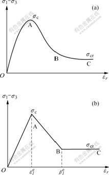
Fig.1 Curves [9-10] of conventional tri-axial compression tests: (a) (��1-��3)����r curve; (b) (��1-��3)����r simplification curve
2.2 Large strain analysis
The small strain in the elastic zone and the large stain in the plastic zone are adopted. The strain��displacement relationship with the small strain theory in the elastic zone is:
![]()
![]() (2)
(2)
The large strain effect adopted the logarithmic strains in the plastic zone. The strains are defined as:
![]()
![]() (3)
(3)
where r0 and u are the radii of a point during loading, in the initial state and the radial displacement of a point in the soil mass, respectively.
2.3 Non-associated flow rule
At the same time, it was decided in this work to adopt the non-associated flow rule in the plastic zone.
![]() (4)
(4)
where h is the softening parameter.
2.4 Conical shear failure
Based on the observations of GRAF [3], the ground surface uplift is associated with a conical shearing failure above the grout bulb. It is reasonable to assume that, at the onset of ground surface upward pressure, the upward pressure exerted by the grout bulb equals the total downward force resulted from the weight of the cone of soil above the grout bulb plus the downward shearing resistance along the cone surface, as shown in Fig.2.
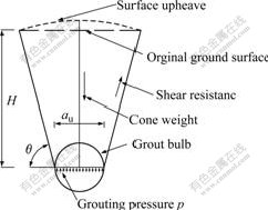
Fig.2 Conical shearing failure above grout bulb
The model governing the upward pressure exerted by the grouted mass in the condition of conical failure above the grout bulb is used according to the above assumption [11-15]. This model is given by the following expression:
 (5)
(5)
where H, pu, ��, ![]() and �� are the injection depth, the injection pressure, the unit weight of the soil, the angle of internal friction and the angle of failure surface to the horizontal, respectively.
and �� are the injection depth, the injection pressure, the unit weight of the soil, the angle of internal friction and the angle of failure surface to the horizontal, respectively.
The growing grout bulb is analogous to a spherical cavity expanding in the stress��strain softening soil mass. According to the assumption, the compaction grout bulb is modeled as an expanding spherical cavity in an isotropic elastic-plastic continuum. Consider an ideal situation in which a grout bulb is injected into the ground after initial without disturbing, the surrounding soil and rock are firmly sealed with the grout pipe. At the beginning of injection, the radius of the bulb, or cavity, is the initial radius a0 and the soil has an isotropic initial pressure p0, as shown in Fig.3. When a uniformly distributed internal pressure at the grout-soil interface, or cavity wall, is increased to pu, the grout bulb radius expands in all the directions to au, and a spherical zone of radius rp around the grout bulb will pass into the state of plastic equilibrium. Beyond the elastic-plastic interface, the soil remains a state of elastic equilibrium. It is assumed that any variation in stress due to body force is negligible when it is compared with the existing and newly applied stresses. Hence, the condition of spherical symmetry holds for the expansion process. The behavior could be described in terms of the spherical polar coordinates, and the equilibrium equation of an element in the plastic zone, at distance r from the center, is given by
![]() (6)
(6)
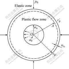
Fig.3 Sketch of cavity expansion
3 Solutions to spherical cavity
3.1 Stress, strain and displacement fields in elastic zone
By means of the elasticity theory, the solutions to the stresses and displacement fields in the elastic zone can be found as
 (7)
(7)
According to the boundary conditions of ��r��r=rp=��rp and ��r=p0, Eqn.(8) is obtained.
![]() (8)
(8)
By using Eqns.(7) and (8) the following expression is obtained:
![]() (9)
(9)
where k is a factor.
3.2 Stress fields in strain softening zone and ultimate grouting pressure
According to the assumption, after initial yielding, the total strain increments can be assumed as the sum of elastic and plastic component:
![]() ,
, ![]() (10)
(10)
where ![]() and
and ![]() denote the radial plastic strain and the circumferential plastic strain in the zone considered, respectively.
denote the radial plastic strain and the circumferential plastic strain in the zone considered, respectively.
Combining Eqns.(2)-(4), the compatibility equation of the strain in the strain softening zone is obtained:
![]() (11)
(11)
The following solution can be obtained by considering boundary conditions at the cavity wall and solving Eqn.(11)
 (12)
(12)
By using the Taylor formulation and ignoring higher order terms of urp/r, as the cavity continues to expand indefinitely, namely when a0/au��0, then rp/a��rp/au, Eqn.(13) is obtained:
![]() (13)
(13)
Combining Eqns.(1) and (6), according to the boundary conditions of ![]() , the radius stress in the strain softening zone becomes:
, the radius stress in the strain softening zone becomes:
![]() (14)
(14)
Considering the boundary conditions of ![]() and ��c=��cr in the cavity wall, the ultimate pressure of the compaction grouting becomes:
and ��c=��cr in the cavity wall, the ultimate pressure of the compaction grouting becomes:
![]()
 (15)
(15)
Eqn.(15) is the grouting pressure at the interface between the grout bulb and the cavity wall.
4 Numerical results
4.1 Limiting injection pressure
The model given by Eqn.(15) is assumed to represent the mechanics and soil response during injection, while that given by Eqn.(5) represents the at failure condition. This pressure value is defined as the upheaval pressure puph which is the onset pressure of ground surface uplift. Although the ultimate pressure has a finite value, as given by Eqn.(15), it could not be attained physically as it requires unlimited growth of the grout bulb. In modeling the compaction grouting technique, it is assumed that the injection process continues until reaching a limiting condition, but in most cases, ground surface uplift is the limiting condition. At ground surface upward pressure, the upward pressure exerted by the grout bulb causes conical shearing failure and upward movement of the truncated cone above the grout bulb. The model given by Eqn.(5) governs this upheaval pressure puph. Therefore, the limiting injection pressure at the grout-soil interface will be governed by puph or pu as shown in Eqn.(15), which is smaller.
4.2 Comparison with actual data
To validate the proposed model, the predicted limiting pressures by the proposed model are compared with those from the real application of compaction grouting. The reported data however does not give specific values of limiting pressures for the given injection depths, but only a wide range. WARNER and BROWN [12] reported that typical maximum pressures experienced at the grout injection point vary from 0.35 to 1.70 MPa when injection is within 1.5 or 1.8 m of the surface and to 3.50 MPa or more when working at depths in excess of 6.0 m. This wide range of maximum pressure values may reflect natural soil heterogeneity. GRAF [3] also reported that the pressures of 2.75-3.50 MPa could be reached normally at depths over 6.0-9.0 m, depending upon the nature of the soil.
WARNER and BROWN [12] reported data for loose Chattahoo-Chee River sand that can be used in this comparison. These data, summarized in Table 1, are the
Table 1 Properties of loose Chattahoo-Chee River sand used in model validation

results of a standard tri-axial test program aimed at investigating the mechanical behavior of the granular materials under high stresses.
Based on the proposed model, Fig.4 shows the curves of ultimate pressures at depths of 3.0 and 6.0 m, using the data of soils B-4 and B-6 in Table 1. The lower and upper limits of the reported actual pressures are 0.35 and 3.50 MPa, respectively.
The ultimate pressure pult and the yield stress pu are shown in Fig.4. The basic parameters [13] are shown as follows: E=1.0 MPa, ��=34.6?, ��=19.6 kN/m3, ��c=1 MPa, k=��cr/��c, ��=0.3.
As seen in Fig.4, all the predicted limiting pressures

Fig.4 Curves of ultimate pressure pult and yield stress: (a) H=3.0 m; (b) H=6.0 m
are within the range of the reported real ones. Although the predicted limiting pressures are all within the reported range, it is noted that the predicted limiting pressures for the 6.0 m in depth injections range from 1.30 to 2.10 MPa, which is considerably less than the maximum reported value of 3.50 MPa. Among grouting techniques, compaction grouting represents an extreme of the range in which the stiffest mortars are injected into the soil. Therefore, the pipe pressure is transferred to the surrounding soil at the grout-soil interface after being attenuated within the grout material. In other words, the pipe pressure is divided into two components: the attenuated pressure (lost in the grout material) and the interface pressure. The model presented herein considers the interface pressure. However, the attenuation factor, which of course, depends on the properties of grout material, is an issue that needs to be investigated. We consider the effects of injections depth being greater than 6.0 m, and the effects of the staged-grouting procedure, existing overlying structure and attenuation of grout material.
5 Conclusions
(1) Experimental results show that strain softening elastic-plastic constitutive model is able to represent fairly satisfactorily the behavior of almost all types of soft soils. Based on the theories of spherical cavity expansion and conical shearing failure above the grout bulb in the strain softening soils, a rational yield function of the soil for the strain softening phase is proposed by using the tri-linear model established from the results of the conventional compression test and the theory of large strain in the plastic zone. The analytical solutions to the compaction grouting pressure are presented.
(2) The comparison indicates reasonable agreement, and shows a good potential of the proposed model for rationally optimizing the design of compaction grouting operations. The proposed model gives an improved understanding of the mechanics associated with compaction grouting and shows a good potential for rationally optimizing the compaction grouting operations.
(3) The model in specific conditions is confirmed, and the model at failure is developed for the given cohesive-frictional soils, considering the effect of injection rate.
References
[1] BOLTON M D, WHITTLE R W. A non-linear elastic/perfectly plastic analysis for plane strain undrained expansion tests [J]. Geotechnique, 1999, 49(1): 133-141.
[2] MILLER E A, ROYCROFT G A. Compaction grouting test program for liquefaction control [J]. Journal of Geotechnical and Geoenvironmental Engineering, 2004, 130(4): 355-361.
[3] GRAF E D. Compaction grouting [J]. Geotechnical Special Publication, 1992, 30(1): 275-287.
[4] NICHOL S C, GOODINGS D J. Physical model testing of compaction grouting in cohesionless soil [J]. Journal of Geotechnical and Geoenvironmental Engineering, 2000, 126(9): 848-852.
[5] YU H S. Expansion of a think cylinder of soils [J]. Computers and Geotechnics, 1992, 14(1): 21-41.
[6] YANG Xiao-li. Seismic displacement of rock slopes with nonlinear Hoek-Brown failure criterion [J]. International Journal of Rock Mechanics and Mining Sciences, 2007, 44(6): 948-953.
[7] YANG Xiao-li, LI Liang, YIN Jian-hua. Seismic and static stability analysis for rock slopes by a kinematical approach [J]. Geotechnique, 2004, 54(8): 543-549.
[8] YANG Xiao-li, YIN Jian-hua. Slope stability analysis with nonlinear failure criterion [J]. Journal of Engineering Mechanics, 2004, 130(3): 267-273.
[9] JIANG Ming-jing, SHEN Zhu-jiang. On expansion of cylindrical cavity with linear softening and shear dilation behavior [J]. Chinese Journal of Rock Mechanics and Engineering, 1997, 16(6): 550-557. (in Chinese)
[10] WANG Jia-lai, XIONG Jian-hua. An analytical solution to cylindrical cavity expansion in softening soil mass [J]. Chinese Journal of Applied Mechanics, 1999, 16(4): 58-62. (in Chinese)
[11] YU H S. Cavity expansion theory and its application to the analysis of pressuremeters [D]. London: University of Oxford, 1990.
[12] WARNER J, BROWN D R. Planning and performing compaction grouting [J]. Journal Geotechnical Engineering, 1986, 100(6): 653-666.
[13] VANDERPOOL W, NORRIS G, ELFASS S. Warning: Low mobility grout may not equal compaction grout [J]. Geotechnical News, 2008, 26(1): 44-50.
[14] WANG Guang-guo, DU Ming-fang, MIAO Xing-cheng. Mechanism of compaction grouting and effect examination [J]. Chinese Journal of Rock Mechanics and Engineering, 2000, 19(5): 670-673. (in Chinese)
[15] EI-KELESH A M, MATSUI T. Calibration chamber modeling of compaction grouting [J]. Geotechnical Testing Journal, 2008, 31(4): 295-370.
(Edited by YANG You-ping)
Foundation item: Project (200550) supported by the Foundation for the Author of National Excellent Doctoral Dissertation of China; Project (09JJ1008) supported by Hunan Provincial Natural Science Foundation of China
Received date: 2008-09-01; Accepted date: 2008-12-21
Corresponding author: YANG Xiao-li, Professor; Tel: +86-731-82656248; E-mail: yxnc@yahoo.com.cn
