
J. Cent. South Univ. (2012) 19: 1610-1614
DOI: 10.1007/s11771-012-1183-2![]()
Heat transfer analysis and experimental verification of cast heat exchanger
YU Jie(���), DONG Lei(����), ZHANG Huan(�Ż�), YOU Shi-jun(������)
School of Environment Science and Technology, Tianjin University, Tianjin 300072, China
? Central South University Press and Springer-Verlag Berlin Heidelberg 2012
Abstract:
From the viewpoints of environmental conservation and energy efficiency, seawater-source heat pump system (SWHP) to provide district cooling and heating is applied in coastal areas. Based on the system, a heat transfer model was established for cast heat exchanger (CHE) adopted by SWHP systems. The CHE consists of pipes immersed in the seawater and used for transferring heat between the seawater and the heat exchanger pipes of SWHP system. An experimental study was carried out to test the validity of the model. A program was developed in VB language and the effects of inlet temperature, flow rate of the secondary refrigerant and length of CHE on the results were investigated. The results of the numerical simulation are in consistence with the experiments in both winter and summer conditions. As a result, application of SWHP systems with CHE in coastal areas in China is feasible due to the favorable geographical conditions and environment.
Key words:
1 Introduction
Recently, new energy installation of HVAC systems in commercial buildings is recommended from the viewpoints of environmental conservation and energy reduction. The new energy is divided into two types, which are natural energy and recycled energy. Seawater is grouped as natural energy. Seawater-source heat pump system (SWHP) is to utilize the seawater for both residential and commercial applications and it offers significant energy use and demand reductions on the power grid [1-4]. Tianjin is an important port in China and is rich in seawater. The geographical factors and recent energy policy provide convenient conditions for the application of SWHP project [5-7].
The application and performance of SWHP system have been paid academic attention. For instance, seawater was used as heat source and sink for district cooling and heating in Dalian, China [8]. AITTOM?KI studied the possibility of using lake water as heat source for heat pump heating in cold climate [9]. B?Y?KALACA et al investigated the Seyhan River and dam lake as heat source�Csink for a heat pump [10]. The project at Cornell University uses the deep, cold water of nearby Cayuga Lake supplying cooling for its campus [11]. The common intake way of SWHP system is composed of the CHE intake way and direct intake way. The direct intake way can be classified into direct and indirect SWHP systems according to whether or not the seawater goes into the unit directly. The CHE intake way belongs to indirect SWHP system [12-14]. Most researches about SWHP use the seawater directly. But one of the biggest challenges of the open loop system is scaling. The water used by the system needs to be recharged to the seawater, so the chemical method cannot be applied. In spite of this, when seawater temperature is low in winter in cold regions, the efficiency of the unit will be greatly reduced, or even the unit would freeze so that the unit cannot run.
Therefore, for the purpose of overcoming the disadvantages of the open loop SWHP in winter in cold regions, a closed loop SWHP system with cast heat exchanger (CHE) is presented in this work. The unit of the closed loop system doesn��t contact with the seawater directly, so there is no scaling in this system. Moreover, because there is no need to overcome the resistance from the distribution point to the unit, the energy consumption in the closed loop system is less than the open loop. In winter operation, the antifreeze solution can be used in this system to avoid freezing. And in the closed loop system, the heat exchanger can get more temperature difference between inlet and outlet fluid to reduce the water flow rate. In the present work, the mathematical model that describes heat transfer process of CHE was established. The validation and parameter studies were conducted and a computer code was implemented to simulate the performance of the cast heat exchanger.
2 Mathematical modeling
The heat transfer between the secondary refrigerant flowing in CHE and seawater outside the heat exchanger goes through three processes as follows:
1) Convective heat transfer between seawater and the outside wall of the pipe;
2) Conductive heat transfer through the pipe wall;
3) Convective heat transfer between the fluid inside the pipe and the inside wall of the pipe.
A schematic diagram of a CHE control volume for heat transfer is illustrated in Fig. 1. The flow direction of the secondary refrigerant is also given in Fig. 1. The CHE is divided into N control volumes equally along the flow direction. And the length of every control volume is ?x. The analysis of every control volume based on the energy balance is performed subjected to the following assumptions [15]:
1) Thermal properties of the pipe and seawater are constant;
2) The temperature and flow rate of fluid in the pipe are uniform at any cross-section;
3) The effect of the curve radius is neglected;
4) The conductive heat transfer along the fluid channels is very small and therefore can be neglected;
5) The model is in the steady state.
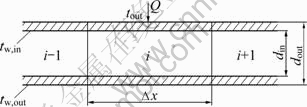
Fig. 1 Schematic diagram of heat transfer between control volume of each segment and seawater
The heat flux due can be written using the following equation:
![]() (1)
(1)
where dout is the diameter of the outer pipe; tsea is seawater temperature; tw,out,i is the temperature of the outer pipe; ro is the fouling coefficient, which is equal to 0.000 6 m2��K/W.
![]() (2)
(2)
where Prsea and Grsea mean Prandtl number and Grashof number, respectively, C is equivalent to 0.48 and n is 0.25 according to the low flow rate of seawater.
![]() (3)
(3)
where din is the diameter of the inner pipe; tw,in,i is the temperature of the pipe inner wall; ��w is thermal conductivity of the pipe, which is equal to 0.49 W/m��K.
![]() (4)
(4)
The flow regime of the fluid in the pipe is forced turbulent flow, so, hin can be determined with the Dittus�C Boelter correlation:
![]() (5)
(5)
where n=0.4 for heating and n=0.3 for cooling.
![]() (6)
(6)
![]() (7)
(7)
where the subscript ��in�� and ��f�� denote the fluid inside the pipe; Prin, uin, ��in are Prandtl number, velocity and kinetic viscosity coefficient, respectively; tf,i is the temperature of the fluid in the pipe.
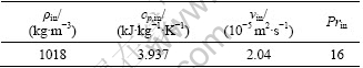
In the present work, a simulation program is developed based on the Visual Basic software. Main parameters for simulation calculations are listed in Table 1. The equations need to be solved iteratively. Using all the equations above, the distribution of temperature along the CHE can be calculated. The fluid temperature distribution along the CHE might be calculated by dividing the whole pipe into small parts in order to calculate fluid inlet and outlet temperature profile along the pipe.
Table 1 Properties of water-ethylene glycol mixture
3 Description of experimental system
In order to validate the mathematic model established above, an experimental rig which simulated the heat transfer process of the CHE was built, as shown in Figs. 2 and 3. It was installed in a towing tank laboratory in Tianjin University. It mainly consisted of the CHE, the heat pump system, the indoor air-condition system and a data acquisition.
A water to water heat pump unit with a hermetic scroll compressor was used here. Its rated power was 3.51 kW and the nominal refrigeration load was 11.4 kW. To avoid freezing of water under the working conditions and during cold winter days, water-ethylene glycol mixture (10% by mass fraction) was used. The refrigerant circuit was built on the closed-loop tubing and the working fluid was R-22. The system can be used for both heating and cooling. The circulations of the glycol solution and the cooling water were driven by circulation pumps. The maximum flow rate of the circulating pumps was 6 m3/h. The CHE consisted of a high-density polyethylene pipe (HDPE) which had 200 m in length and 32 mm in outer diameter submersed in a water reservoir at 3 m. The model of the CHE is shown in Fig. 4.

Fig. 2 Flow diagram of experimental system in winter mode: 1-Fan coil; 2-Heat pump unit; 3-Expansion tank; 4-Electric heater; 5-Contact type voltage regulator; 6-Stem thermometer; 7-Pressure meter; 8-Cast heat exchanger; 9-Automatic exhaust valve; 10-Float-flow-meter; 11-Pump
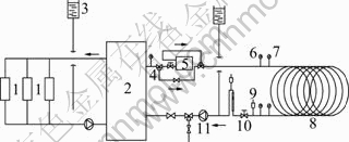
Fig. 3 Flow diagram of experimental system in summer mode: 1-Fan coil; 2-Heat pump unit; 3-Expansion tank; 4, 6-Stem thermometer; 5-Fan coil pipe; 7-Pressure meter; 8-Cast heat exchanger; 9-Automatic exhaust valve; 10-Float-flow-meter; 11-Pump

Fig. 4 Configuration view of CHE model
The glycol solution is circulated through the polyethylene pipe by pump to extract the energy of the water as a heat source or a heat sink. In winter operation, the heat obtained from the water through the CHE is dissipated to the heating space; in summer operation, the heat obtained from the conditioned space (i.e. building) is dissipated to water through CHE.
In order to measure the glycol solution temperature distribution along the CHE, seventeen T-type copper- constantan thermocouples with ��0.5 �� accuracy are embedded every other 10 m along the wall of the CHE. To make sure the accuracy of the test temperature, the welded parts were wrapped in heat insulating material. Before the installation, all sensors were calibrated by constant-temperature water bath with ��0.1 �� accuracy. The layout of the temperature sensors is shown in Fig. 5.

Fig. 5 Layout of temperature sensors
4 Experimental validation
The parameters correlated with the model validation in the experimental system are listed in Tables 1 and 2.
Table 2 Properties of surface water
![]()
For the CHE model, the test may be performed by the comparison on the outlet temperature of CHE between the experimental value and the calculated value by the model under the given inlet temperature and flow rate.
When the flow rate is 0.8 m3/h, the calculated temperature distribution along CHE and corresponding test data in winter and summer operation are compared respectively. The results are shown in Figs. 6 and 7. The relative error is less than 5%, which is acceptable in engineering application and simulation results show great agreement with experimental data. This means that the mathematical model developed above can simulate effectively the heat transfer process of CHE.
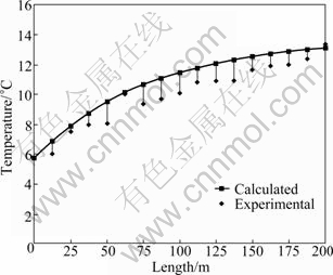
Fig. 6 Comparison of calculated temperature distribution along CHE and test value in winter mode
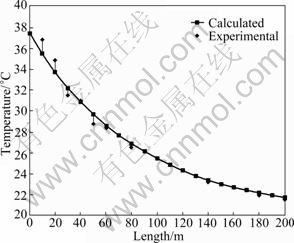
Fig. 7 Comparison of calculated temperature distribution along CHE and test value in summer mode
5 Parametric studies
The heat transfer performance of the CHE involves many factors. A parametric study provides the information to determine the relative importance of each factor and thus to improve the heat transfer performance of CHE. The parameters selected for investigation were: pipe length, inlet temperature, flow rate in the pipe and temperature of seawater.
As the basis for comparison, a base run was completed with the following parameters and operation conditions: 1) for 32 mm nominal diameter high-density polyethylene (HDPE) pipe, the pipe length is 200 m; 2) inlet temperature of the fluid in the pipe is 0 ��; 3) temperature of seawater is 5 ��; 4) circulation solution in the pipe is water-ethylene mixture (10% by mass fraction).
5.1 Pipe length
The pipe length is an important parameter of CHE design. In order to analyze the effect of pipe length on heat transfer performance, an operation condition with the flow rate of fluid at 0.4, 0.5 and 0.6 m/s is performed. Figure 8 shows the effect of pipe length on heat transfer performance at different flow rates. It can be found that there is a comparatively large curve slope with the cast heat exchanger length from 60 m to 160 m. While the length increases from 160 m to 200 m, the enhancement of heat transfer performance is inclined to even and the heat transfer performance increase can be neglected with the length increasing from 220 m to 280 m. With the increase of CHE length, the frictional resistance which losses along the pipe will also increase. So it is not cost effective to have a very long heat exchanger.
5.2 Inlet temperature
In the heat transfer process, the fluid inlet temperature influences the heat transfer performance of CHE. Figure 9 presents that the heat transfer rate of CHE varies with the fluid inlet temperature from -3 �� to 3 �� with the flow rate of fluid at 0.4, 0.5 and 0.6 m/s. It can be detected from Fig. 9 that the trend of the heat transfer performance variation is approximately the same as the tendency of the secondary coolant inlet temperature under different flow rates. This indicates that the heat flux drops linearly with the inlet temperature enhancing. This is because under the low inlet temperature, the temperature difference between the secondary coolant and seawater is comparatively large, so the heat transfer is strengthened.
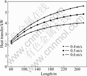
Fig. 8 Effect of pipe length on heat transfer under different flow rates
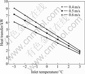
Fig. 9 Effect of inlet temperature on heat transfer under different flow rates
5.3 Flow rate in heat exchanger
Flow rate in the CHE is also an important influencing factor on the heat transfer performance. Flow rate in the heat exchanger affects coefficient of heat transfer, and influences the heat transfer performance. Figure 10 displays that the variation trend of the heat flux is approximately the same as the flow rate at different inlet temperatures. When the inlet temperature is constant, the heat flux increases as the flow rate rises. However, the variation tendency is slow. It can be seen that when the flow rate is increased from 0.4 m/s to 0.55 m/s, the slope of curve becomes large, demonstrating the heat flux has a great increase as the flow rate changes from 0.4 m/s to 0.55 m/s; when the flow rate increases from 0.55 m/s to 0.7 m/s, the heat flux variation can be neglected. This indicates that the increase rate of heat flux decreases with per-unit flow rate increasing and the increase of the flow rate. Moreover, with the increasing flow velocity, the frictional resistance losses with the pipe increasing. So the energy consumption by the circulation pump increases. It can be found from Fig. 9 that the amount of heat transfer increases at 0.4 m/s with respect to 0.6 m/s is about 32.9%, while the frictional resistance losses along the pipe increase by 103.3%.
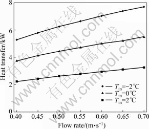
Fig. 10 Effect of flow rate on heat transfer under different inlet temperatures
6 Conclusions
1) The pipe length, flow rate and seawater temperature are used in computer simulation and the results are satisfactory. The temperature distributions along the CHE of the simulation are very close to the temperatures measured from the experimental work. The relative error is less than 5%, which is acceptable in engineering application.
2) At the constant inlet temperature and flow rate of the secondary coolant, the heat flux increases with the increase of the pipe length. But with the pipe length increasing, the frictional resistance losses along the pipe increase.
3) The heat flux increases with increasing the flow rate and the increasing rate is slow when the inlet temperature of the secondary coolant is constant. But with the increase of the flow rate, the pump lift rises.
4) The heat flux per pipe length can be increased when the temperature difference between inlet and seawater temperature becomes larger.
5) The use of ocean thermal energy in Tianjin shows a promising prospect in the near future and has great potential for development in coastal cities in China.
References
[1] SONG Y, YASUNORI A. Effects of utilizing seawater as a cooling source system in a commercial complex [J]. Energy and Buildings, 2006, 39: 1080-1087.
[2] WU Rong-hua, ZHANG Cheng-hu. Energy-saving and environ- mental evaluation of surface-water source heat-pump system [J]. Journal of Harbin Institute of Technology, 2008, 40: 226-229. (in Chinese)
[3] CHEN Xiao, ZHANG Guo-qiang, PENG Jian-guo. The performance of an open-loop lake water heat pump system in south China [J]. Applied Thermal Engineering, 2006, 26: 2255-2261.
[4] YANG H, CUI P, FANG Z. Vertical-borehole ground-coupled heat pumps: A review of models and systems [J]. Applied Energy, 2009, 87: 16-27.
[5] V?rtan Ropsten��the largest seawater heat pump facility worldwide, with 6 Unitop? 50FY and 180MW total capacity [EB/OL]. [2008]. http:// www.friotherm.com/downloads/vaertan_e008_uk.pdf.
[6] SATORU O. A heat pump system with a latent heat storage utilizing seawater installed in an aquarium [J]. Energy and Buildings, 2005, 38: 121-128.
[7] YU Yan-shun, MA Zui-liang, LI Xian-ting. A new integrated system with cooling storage in soil and ground-coupled heat pump ground source heat pump description and preliminary results of the eco house system [J]. Applied Thermal Engineering, 2007, 28: 1450- 1462.
[8] LI Zhen, LIN D, SHU H. District cooling and heating with seawater as heat source and sink in Dalian, China [J]. Renewable Energy, 2007, 32: 2603-2616.
[9] AITTOM?KI A. Lakes as a heat source in cold climate [C]// Proceedings of 21st IIR International Congress of Refrigeration. Washington, 2003: 88-92.
[10] B?Y?KALACA O, EKINCI F, YILMAZ T. Experimental investigation of Seyhan River and dam lake as heat source-sink for a heat pump [J]. Energy, 2003, 28: 157-169.
[11] TIM P, JOYCE W. Lake-source cooling [J]. ASHRAE Journal, 2002, 44: 37-39.
[12] KAVANAUGH S, RAFFERTY K. Ground-source heat pump: Design of geothermal systems for commercial and institutional buildings [M]. Atlanta: ASHRAE Inc, 1997: 145-197.
[13] PARSONS R. ASHRAE handbook-heating, ventilating, and air- conditioning systems and applications [M]. Atlanta: ASHRAE Inc, 1987: 249-288.
[14] PARSONS R. ASHRAE handbook-systems [M]. Atlanta: ASHRAE Inc, 1980.
[15] TAO Wen-shuan. Numerical heat transfer [M]. 2nd Edition. Xi��an: Xi��an Jiaotong University Press, 2001: 1-47. (in Chinese)
Foundation item: Project(2006BAJ04A15-03) supported by the National Science and Technology Pillar Program during the Eleventh Five-year Plan Period
Received date: 2011-07-26; Accepted date: 2011-11-14
Corresponding author: ZHANG Huan, Professor; Tel: +86-22-27892626; E-mail: zhhuan@tju.edu.cn
Abstract: From the viewpoints of environmental conservation and energy efficiency, seawater-source heat pump system (SWHP) to provide district cooling and heating is applied in coastal areas. Based on the system, a heat transfer model was established for cast heat exchanger (CHE) adopted by SWHP systems. The CHE consists of pipes immersed in the seawater and used for transferring heat between the seawater and the heat exchanger pipes of SWHP system. An experimental study was carried out to test the validity of the model. A program was developed in VB language and the effects of inlet temperature, flow rate of the secondary refrigerant and length of CHE on the results were investigated. The results of the numerical simulation are in consistence with the experiments in both winter and summer conditions. As a result, application of SWHP systems with CHE in coastal areas in China is feasible due to the favorable geographical conditions and environment.
