
J. Cent. South Univ. (2012) 19: 2152-2157
DOI: 10.1007/s11771-012-1258-0![]()
Electromagnetic analysis and design of in-wheel motor of micro-electric vehicle based on Maxwell
CHEN Qi-ping(����ƽ)1, SHU Hong-yu(�����)1, REN Kai(�ο�)1,
ZHUANG Shen(ׯ��)1, XIE An-yuan(л��Դ)2
1. State Key Laboratory of Mechanical Transmission (Chongqing University), Chongqing 400030, China;
2. Chongqing Senci Electrical & Mechanical Co., Ltd., Chongqing 400700, China
? Central South University Press and Springer-Verlag Berlin Heidelberg 2012
Abstract:
To obtain a good drivability and high efficiency of the micro-electric vehicle, a new driving in-wheel motor design was analyzed and optimized. Maxwell software was used to build finite element simulation model of the driving in-wheel motor. The basic features and starting process were analyzed by field-circuit coupled finite element method. The internal complicated magnetic field distribution and dynamic performance simulation were obtained in different positions. No-load and load characteristics of the driving in-wheel motor was simulated, and the power consumption of materials was computed. The conformity of the final simulation results with the experimental data indicates that this method can be used to provide a theoretical basis to make further optimal design of this new driving in-wheel motor and its control system, so as to improve the starting torque and reduce torque ripple of the motor. This method can shorten the development cycle of in-wheel motors and save development costs, which has a wide range of engineering application value.
Key words:
micro-electric vehicle; in-wheel motor; Maxwell; simulation; optimization��
1 Introduction
In recent years, electric vehicles have an extraordinary development in many countries of the world because of their advantages of emission-free, low noise, energy saving and high efficiency, and the micro-electric vehicle used for short distance transport is a hot research issue today [1-3]. So, a new permanent magnet brushless direct circuit in-wheel motor for the micro-electric vehicle had been designed and developed. This new kind of motor is installed in the wheel of micro-electric vehicle, and by this form the utilization of body space could increase and the traditional clutch, gear, transmission bridge and other mechanical components could be abandoned [4]. In-wheel motor has the advantages of reducing mass, cutting down mechanical losses and improving the driving sensitivity. Therefore, it is necessary to study a new type driving in-wheel motor of micro-electric vehicle which possesses the merits of high efficiency, high starting torque, low noise, no excitation loss, high reliability and good velocity modulation performance, in order to meet the development requirements of micro-electric vehicle in lightweight, safety, energy conservation and environmental protection.
Since in-wheel motor is important for the electric vehicle, it is necessary to design and research. General Motors Corporation designed a kind of in-wheel motor which was applied to the Chevrolet S-10. Keio University in Japan developed IZA, ECO, KAZ and other electric vehicles, which also adopted the driving in-wheel motor. Tongji University developed the ��springfield�� series fuel cell concept vehicle, which used a brushless direct circuit in-wheel motor to drive each wheel independently [5-6]. Although their researches have improved the power, torque and acceleration performance of in-wheel motor, the speed modulation and overall performance are not very satisfactory. There are many performance analysis methods about the in-wheel motor, such as direct circuit motor analysis, state equation simulation, analytic method of electromagnetic field and electromagnetic finite element numerical method. In particular, finite element numerical analysis method is widely used in the analysis and calculation of various electrical equipments, and it can consider the circumstance of nonlinear ferromagnetic materials, as well as the changes of parameters in motor [3]. The electromagnetic analysis software of Maxwell was adopted to emulate the basic characteristics and the starting process of the complex in-wheel motor. The results show this method is rational and feasible.
2 Establishment of mathematical model
Circuit equation of driving in-wheel motor is a six-star connected three-winding state operation [3]. When the in-wheel motor is in the converter mode, the three-phase windings are on powered simultaneously. The circuit equation is shown as Eq. (1) and the midpoint potential is shown as Eq. (2).
 (1)
(1)
![]() (2)
(2)
The performance analysis of in-wheel motor is based on time-domain mathematical model, so the phase voltage equation in matrix form is shown as
 (3)
(3)
where ua, ub and uc are terminal voltages of points a, b and c; um is the center point electric potential of the star winding; w is the revolution in the form of electrical radians; r is the armature winding resistance; la is d-axis synchronous inductance; lb is q-axis synchronous inductance; lc is o-axis inductance. Under these voltages, current and total power loss of input power and output power are shown in Eqs. (4)-(5). The output mechanical torque is shown as Eq. (6), and motor efficiency is shown as Eq. (7):
![]() (4)
(4)
![]() (5)
(5)
Tout=Pout/w1 (6)
![]() (7)
(7)
3 Establishment of two-dimensional finite element model
The model of driving in-wheel motor was established and analyzed by Maxwell software. At first, according to the requirement of the micro-electric vehicle��s control system, the main technical parameters of the in-wheel motor could be optimized, as given in Table 1. Then, two-dimensional finite element model was established by Maxwell 2D software, as shown in Fig. 1. Finally the no-load and load of in-wheel motor were computed and analyzed in the transient state module of Maxwell 2D.
Table 1 Main technical parameters
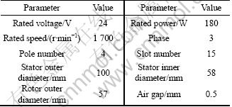
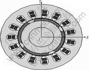
Fig. 1 Two-dimensional finite element model (Time: 0.03 s)
3.1 Control circuit system
To make an accurate simulation analysis, Maxwell circuit editor module in Ansoft software was adopted to establish the external circuit model and a complete finite element model along with the geometric model was established [7]. Control circuit system of the driving in-wheel motor is mainly made up of the model of drive circuit and power converter. Control circuit system is shown in Fig. 2. Here, V32 and V33 are voltage sources; D34-D45 are diodes; S_46-S_51 are voltage controlled switches; V14-V19 are pulse voltage sources; IVc1- IVc6 are voltmeters; VIA-VIC are ampere meters.
MOSFET power controllable switches and diodes were applied to simulate controllable switch silicon devices in the actual brushless DC in-wheel motor circuit. Diodes which were in series with the controllable switch were used to set the actual voltage drop. Besides, eight diodes were required as freewheeling loop. Pulse voltage sources, ground voltage meters and resistors were applied to the drive circuit model.
3.2 Subdivision of finite element grid
To ensure the accuracy of magnetic circuit calculation and magnetic field analysis, finite element grid was subdivided by manual mode. The magnetic field was divided into 20 094 units by the methods of inside selection and surface approximation [8-10]. The overall subdivision model and the partial enlargement model are shown in Figs. 3(a) and (b), respectively.
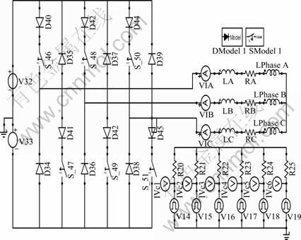
Fig. 2 Control circuit system
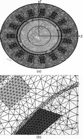
Fig. 3 Grid subdivision model (Time=0.03 s): (a) Overall subdivision model; (b) Partial enlargement model
The subdivision of finite element grid is relatively uniformly distributed on the whole, and the grid subdivision has a higher density in the field where the magnetic field is relatively strong and changes greatly, such as the air-gap part. Therefore, the subdivision of finite element grid can reach the desired effect and satisfy the accuracy of finite element calculation.
4 Simulation and results analysis
A two-dimensional transient simulation of the driving in-wheel motor in the Maxwell 2D module of software Ansoft and a motor bench experiment were made in this work.
4.1 Analysis of electromagnetic field
Analysis and research of the distribution of magnetic line and the cloud map of the magnetic flux density were made at the transient simulation time of 30 ms. The results are shown in Figs. 4 and 5, respectively. And the remaining can also be analyzed in the same way. Figure 4 shows that the red magnetic line of force is positive extreme, the blue magnetic line of force is negative extreme and there must be flux leakage in stator slots. Figure 5 shows that the magnetic flux density is higher in yoke department of the motor and exhibits deeper color which results from permanent magnets.
The air gap electromagnetism is a key structure design parameter of the driving in-wheel motor, and the size of the micro-gap has an important influence on the starting performance of micro-electric vehicles. Through
the simulation and computation of the air gap electromagnetism, the flux density distribution of air gap (Mag_B) in the different paths was obtained, as shown in Fig. 6, and three-dimensional images of center air gap is shown in Fig. 7. Figures 6 and 7 show that flux density distribution of the different paths is quite even, which can reduce the start torque ripple of the driving in-wheel motor, thereby improving the drive performance of micro-electric vehicles [11].
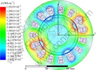
Fig. 4 Distribution of magnetic line
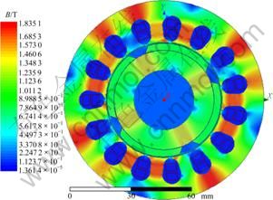
Fig. 5 Cloud map of magnetic flux density
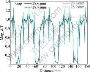
Fig. 6 Flux density distribution of different paths
Through analyzing the distribution of magnetic line, cloud map of the magnetic flux density and the air gap electromagnetism, the specific distribution of internal
complicated magnetic field in the motor and magnetic saturate situation of each part can be ascertained in this work, so as to provide a better theoretical basis to optimize the structure of the motor.
4.2 Analysis of dynamic process
The induced voltages of the no-load and load of in-wheel motor were carried on simulation computation, and the simulation results were compared, as shown in Fig. 8. Figure 8 shows that the load voltage distribution of stator winding is non-sinusoidal and approximately less than no-load voltage of sinusoidal distribution. The armature magnetic field of load current can demagnetize. At the same time, Fig. 8 can also vividly describe the change phase process of in-wheel motor.
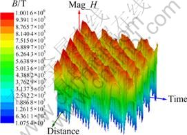
Fig. 7 Three-dimensional distribution of center air gap
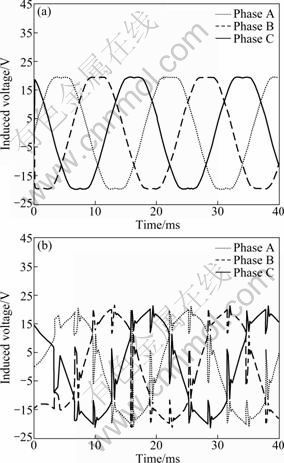
Fig. 8 Coil induced voltage contrast: (a) No-load induced voltage; (b) Load induced voltage
4.3 Analysis of power loss
Under the pulse width modulation control voltage, to obtain the ferromagnetic material losses of the stator and rotor, ferromagnetic material loss based on bertotti separation iron loss computation model, which was supplied by the standard sine voltage, should be calculated firstly [12-13].
![]() (8)
(8)
![]() (9)
(9)
![]() (10)
(10)
where f is the magnetic field frequency; T is the magnetic field cycle; Ped is the eddy current loss; Ked is the coefficient of eddy current loss; Pan is abnormal loss; Kan is the coefficient of abnormal loss; Phy and x are the hysteresis loss; Khy is the coefficient of hysteresis loss; Bam is the flux density amplitude.
In the alternating voltage supply model, if the instantaneous value of the total voltage and fundamental always maintain the same direction, it is easy to infer the following equations:
u(t)=uamsin(wt) (11)
![]() (12)
(12)
Psin=Ped+Phy+Pan (13)
![]()
![]() (14)
(14)
where u(t) is the standard sinusoidal voltage; uam is the standard sinusoidal voltage amplitude; N is the number of turns; S is cross-sectional area of ferrite core.
When PWM (pulse width modulation) supplies power, if the carrier ratio is large enough, it can be approximately considered that the PWM average voltage is equal to the fundamental voltage, and then their hysteresis losses are also equal. The material loss of PWM power supply can be derived from the material loss of the sinusoidal power supply:
 (15)
(15)
where Jn is the Bessel function; n and h are a natural number; M is carrier ratio; usin_rms is the effective value of fundamental wave.
The in-wheel motor designed made use of Toyota Corporation��s prius ferrite core material. According to the previous equations, it is easy to describe the material loss curves of different frequencies, as shown in Fig. 9.
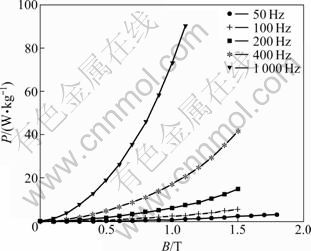
Fig. 9 Material loss curves of different frequencies
Figure 10 shows that the torque ripple has a relatively large influence on the motor power loss during the starting, but during stable operation, the power loss influence is relatively small, approximately 3 W. Therefore, this in-wheel motor possesses higher efficiency, which can perfectly meet the micro-electric vehicle needs.
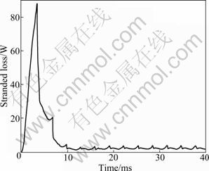
Fig. 10 Power loss curve
4.4 Experiment
To observe the changes of performance parameters between the initial moment and steady-running moment, when in-wheel motor was in load starting, the simulation of mechanical transient state was operated [14-15]. A motor bench experiment was made to confirm simulation results. The experiment method depended on the national standard GB/T 1311��2008, and the boundary condition adopted the vector potential boundary. Comparison of electromagnetic torque and comparison of speed are shown in Fig. 11. The simulation and experimental results are basically consistent. Figure 11(a) shows that there are comparatively heavy torque ripple among the initial 8 ms, but the torque ripple becomes relatively small after 8 ms, which results from the equilibrium of torque. This can be improved by the change of the structure and control strategy of the permanent magnets. The speed curve is shown in Fig. 11(b). The driving in-wheel motor could reach steady state about 8 ms, so it could fully meet the starting needs of micro-electric vehicles. Experiment and simulation error is less than 3%, which can meet the rotary motor national standard GB 755��2008.
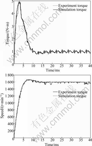
Fig. 11 Comparison of experiment and simulation: (a) Comparison of electromagnetic torque; (b) Comparison of speed
5 Conclusions
1) The finite element analysis software Maxwell 2D is adopted to establish the simulation model of brushless direct circuit in-wheel motor which drives micro-electric vehicle, and the dynamic performance research of driving in-wheel motor is accurately accomplished. Simulation results show that the internal magnetic field distribution is reflected accurately, and also provide a theoretical basis to make further optimal design this new type in-wheel motor structure.
2) The main properties of in-wheel motors include electromagnetic torque, speed, winding induced voltage and power loss, etc., which can provide a reference to reduce torque ripple, improve the starting torque and make further optimal design of control system.
3) This method can shorten the development cycle of in-wheel motors and save development costs, which has a wide range of engineering application value.
References
[1] CHU W Q, GU C. Applications and developing trend of in-wheel motors home and abroad [J]. Small Electrical Machines, 2007, 40(7): 77-81.
[2] GU C. Comprehensive review of electric vehicle PM wheel motors [J]. Micromotor, 2008, 41(2): 56-59.
[3] LIU Rui-fang, YAN Deng-jun, HU Min-qiang. Field circuit and movement coupled time stepping finite element analysis on permanent magnet brushless DC motors [J]. Proceedings of the CSEE, 2007, 27(12): 59-64. (in Chinese)
[4] LORENZO R, ENRICO B, FABI O. Preliminary experimental evaluation of a four wheel motors, batteries plus ultracapacitors and series hybrid powertrain [J]. Applied Energy, 2011, 88(2): 442-448.
[5] SON H, LEE K. Two DOF magnetic orientation sensor using distributed multipole models for spherical wheel motor [J]. Mechatronics, 2011, 21(1): 156-165.
[6] WANG J, WANG Q, JIN L, SONG C. Independent wheel torque control of 4WD electric vehicle for differential drive assisted steering [J]. Mechatronics, 2011, 21(1): 63-76.
[7] ZHAO Bo, ZHANG Hong-liang. Ansoft 12 in project electromagnetic field application [M]. Beijing: China Water Power Publications, 2010: 153-174. (in Chinese)
[8] YANG Z B, HUANG Z Y, ZHANG X H. Simulation and analysis starting performance of switched reluctance motor based on ansoft/maxwell 2D [J]. Micromotor, 2009, 42(8): 19-22.
[9] ZHANG Wen-ming, LI Wei-li, SHEN Jia-feng. Calculation and simulation of the back EMF and cogging torque of brushless DC motor [J]. Journal of Harbin Institute of Technology, 2006, 38(2): 297-300. (in Chinese)
[10] WANG Ji-qiang, WANG Feng-xiang, KONG Xiao-guang. Design and analysis of electromagnetic properties for high speed PM generator [J]. Proceedings of the CSEE, 2008, 28(20): 105-110. (in Chinese)
[11] HYUNG B I, HONG H Y, CHUNG J T. Dynamic analysis of a BLDC motor with mechanical and electromagnetic interaction due to air gap variation [J]. Journal of Sound and Vibration, 2011, 330(8): 1680-1691.
[12] HUANG Ping-lin, HU Qian-sheng, CUI Yang, HUANG Yun-kai. Analytical calculation of the iron losses of electric machine fed by PWM inverter [J]. Proceedings of the CSEE, 2007, 27(12): 19-26. (in Chinese)
[13] XU P, HOU Z, GUO G F, XU G, CAO B G, LIU Z C. Driving and control of torque for direct-wheel-driven electric vehicle with motors in serial [J]. Expert Systems with Applications, 2011, 38(1): 80-86.
[14] HWANG C C, CHANG J J. Design and analysis of a high power density and high efficiency permanent magnet DC motor [J]. Journal of Magnetism and Magnetic Materials, 2000, 209(2): 234-236.
[15] WANG R, CHEN Y, FENG D W, HUANG X Y, WANG J M. Development and performance characterization of an electric ground vehicle with independently actuated in-wheel motors [J]. Journal of Power Sources, 2011, 196(8): 3962-3971.
(Edited by DENG L��-xiang)
Foundation item: Project(CSTC2009AC6051) supported by Ministry of Major Science & Technology of Chongqing, China; Project(CDJXS12110010) supported by the Fundamental Research Funds for the Central Universities, China
Received date: 2011-05-20; Accepted date: 2011-07-18
Corresponding author: SHU Hong-yu, Professor, PhD; Tel: +86-23-65103568; E-mail: 284416392@qq.com
Abstract: To obtain a good drivability and high efficiency of the micro-electric vehicle, a new driving in-wheel motor design was analyzed and optimized. Maxwell software was used to build finite element simulation model of the driving in-wheel motor. The basic features and starting process were analyzed by field-circuit coupled finite element method. The internal complicated magnetic field distribution and dynamic performance simulation were obtained in different positions. No-load and load characteristics of the driving in-wheel motor was simulated, and the power consumption of materials was computed. The conformity of the final simulation results with the experimental data indicates that this method can be used to provide a theoretical basis to make further optimal design of this new driving in-wheel motor and its control system, so as to improve the starting torque and reduce torque ripple of the motor. This method can shorten the development cycle of in-wheel motors and save development costs, which has a wide range of engineering application value.
