
DOI: 10.11817/j.issn.1672-7207.2017.02.011
�������������ϱ������쳤�ȵĹ�ϵ
���ľ֣꣬�ϣ��μ�����������������ʣ�����
(���ϴ�ѧ �����ܸ�����������ص�ʵ���ң����� ��ɳ��410083)
ժ Ҫ��
�������������ϱ������쳤��֮��Ĺ�ϵ��������������ʵ���о�Ԥ����ϱȺ�Ԥ�����쳤����Ϊ��ֹͣ�⣬ʵ����ϱȺ�ʵ�����쳤�ȵķֲ����ɡ��о����������Ԥ����ϱ���Ϊ��ֹͣ�������£�ʵ�����쳤�ȵ���ɢ��С��0.5 mm��Ԥ�����쳤����Ϊ��ֹͣ�������£�����Ԥ�����쳤�ȵ����ӣ�ʵ����ϱȵ���ɢ����1.13%���ӵ�21.16%����Ԥ�����쳤����12.0~12.6 mmʱ��ʵ����ϱ�y���������쳤��x֮��������Թ�ϵy = 177.3-6.5x�����о�Ϊ������������������칤�����豸�ĸĽ����Ż��ṩ�����뼼��������
�ؼ��ʣ�
�������������ϱ������쳤������������ӳ���ϵ��
��ͼ����ţ�TN253 ���ױ�־�룺A ���±�ţ�1672-7207(2017)02-0343-05
Relationship between coupling ration and elongation length for fused tapered optical fiber couplers
LI Wenjuan, ZHENG Yu, DUAN Jian, WANG Lijun, LI Jipan, L Wen
Wen
(State Key Laboratory of High Performance Complex Manufacturing, Central South University, Changsha 410083, China)
Abstract: In order to explore the relationship between coupling ration and elongation length for fused tapered optical fiber couplers, the preset coupling ratio and the preset elongation length as the elongation stopping criterion were discussed, and also the regularities of distribution about the actual coupling ratio and elongation length were researched on the basis of the experiments about fused biconical taper. The results show that when the preset coupling ratio is treated as stopping criterion, the dispersion of actual elongation length is less than 0.5 mm; when the preset elongation length is treated as the stopping criterion, the dispersion of actual couping ratio increases from 1.13% to 21.16% with the increase of the elongation length. There is a linear relationship: y=177.3-6.5x, between the actual coupling ratio (y) and the elongation length (x) when the elongation length is undulate in 12.0 to 12.6 mm. This research provides the theoretical principle and supporting technology for improving and optimizing the manufacturing process and equipment in fiber baconical taper.
Key words: optical fiber coupler; coupling ratio; drawing length; fused biconical tapered; mapping relationship
�����������һ���ǽ��Ⲩ��1�������з�����������л��߽���������к���1�����˵���Դ�������ڹ���ͨ������˴��е������й㷺��Ӧ��[1-4]�������췽ʽ������������ѧʽ�Լ��Ⲩ��ʽ3��[4-6]������ͨ��������(ͨ������4)��һ����������������죻ͨ�����ϴ�(ͨ������8)��һ����ùⲨ�������졣���������ǽ�2����Ϳ����Ĺ��˲���һ���������죬ʹ����о����һ�𣬻��ڵ�ģ���˼����ų����ϵ�ԭ�����Դﵽ�Ⲩ��ϡ����۷����ж��֣���������[7]�������[8]���������[9-10]�ȣ�Ŀǰ���õ�����������ȣ�����̲����������豸�Ļ�е����(�����ղ���)�����ƣ�������ͷ���ȸ߶ȡ����������������ٶ��Լ�����ʱ��ȣ���ֹͣ����Ԥ����ϱ�Ϊ�����������������ɹ�ѧԭ����ṹ��ơ�����ԭ���빤����ȷ����������������ʹ�Ⲩ�ڹ���-�����Ͻ������Ԥ����Ϊ��ʵ�ֹ�ѧԭ���빦�ܵĹ��̣����ѧ���������칤�ղ���ǿ����������������[5-6]������������о���Ա���������[2-4]�����칤�����豸[14]��������ò[11-13]����ѧ����(�總����ġ�ƫ�������ġ������Ե�)[15-18]�����������о�������ĿǰΪֹ�����е���ֹͣ�������Ԥ����ϱ�Ϊ������Ԥ����ϱȺ�ʵ�����쳤���к�ӳ���ϵ���ܷ���Ԥ�����쳤����Ϊֹͣ�⡢Ԥ�����쳤����ʵ����ϱ��к�ӳ���ϵ�������������ױ���������������1��2�Ĺ������������������Ϊ�о�����ͨ��Ԥ����ϱȺ�Ԥ�����쳤����Ϊ��ֹͣ�⣬��̽��Ԥ����ϱȺ�ʵ�����쳤�ȵķֲ�������ӳ���ϵ���Լ�Ԥ�����쳤����ʵ����ϱȵķֲ�������ӳ���ϵ��
1 ʵ��
1.1 ʵ��װ��
����ʵ����������ʵ��ƽ̨���豸������ṹ��ͼ��ͼ1��ʾ����ƽ̨�ɹ�Դ���˶�ƽ̨������ϵͳ���������ϵͳ��ɡ���Դ���ü����Դ�����ṩ1 310��1 550 nm˫�����Ĺ⣻�������˶�ƽ̨�������˼оߡ���װ�á��մɻ�ͷ�Լ���װ�о��ƶ�װ�ã�����ϵͳ��I/O�ӿڽ���������̽�������������������������ӣ��������ϵͳ���ڼгֹ��ˡ�
ʵ��ƽ̨����ʱ���ԳƵĹ��˼г�װ���ڲ�������������ص������趨�����ٶ��������ƶ������̽������̽��Ĺ��ת���ɵ��ź�, ����ģ��ת����·ת���������źŲ����͵������ϵͳ, ���������Щ���ݴ�����, ������Ӧ�ķֹ�ȡ�������ĺ�����ĵȲ���, ��ʵʱ��ʾ����ʾ���ϣ�������˴ﵽԤ���趨�ķֹ�Ȼ����쳤��ʱ, ����������Զ�ֹͣ����, ����ƽ̨�Զ�ֹͣ���������˳����档
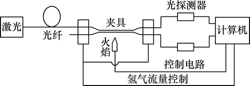
ͼ1 ���������ʵ���ͼ
Fig. 1 Experimental system of optical fiber coupler
1.2 ʵ�����
ʵ��ѡ�ÿ���SMF-28e���ˣ���о�������ڹⲨ����1 550 nm��Ϊ1.465 8��о��Ϊ 8.2 ��m��о���������ʲ�Ϊ0.36%���⾶Ϊ125 ��m�������Դ����Ϊ1 550 nm��ʵ���������ٶȦ�Ϊ150 ��m/s����ͷ�߶�Ϊ5.75 mm������Ϊ23 �桢��������Ϊ180 cm3/s������֤Ԥ����������Ť�ʳ̶Ⱥͽ��һ���������½��еģ��豸�����������ȶ���״̬��
���������ղ����£�ʵ��1ͨ���ı�Ԥ����ϱȣ���ò�ͬԤ����ϱ���ʵ�ʵ���ϱȺ�ʵ�ʵ����쳤�ȣ�ÿ�μ�¼50�����ݡ���ͬ���Ĺ��������£�ʵ��2ͨ���ı�Ԥ�����쳤�ȣ�����ڲ�ͬԤ�����쳤����ʵ�ʵ����쳤�Ⱥ�ʵ�ʵ���ϱȣ�ͬ��ÿ�μ�¼50�����ݡ�ʵ��1��ʵ��2�ĸ�����Ŀ�����0.3 dB�ڡ�ʵ��1������ĵ�ƽ��ֵΪ0.10~0.13 dB����ƫ��Ϊ0.04~0.06 dB��ʵ��2������ĵ�ƽ��ֵΪ0.12~0.15 dB����ƫ��Ϊ0.05~0.07��ͼ1��ͼ2��ʾΪ������ĵ���ɢ�ֲ������
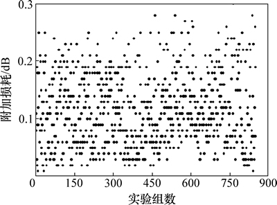
ͼ2 ʵ��1������ĵķֲ�
Fig. 2 Distribution of excess loss for experiment 1
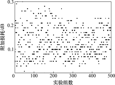
ͼ3 ʵ��2������ĵķֲ�
Fig. 3 Distribution of excess loss for experiment 2
2 ����������
2.1 Ԥ����ϱ���
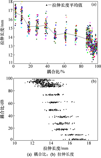
ͼ4��ʾΪ��Ԥ���趨��ϱȵ������£�ʵ�ʻ�õ���ϱ���ʵ�����쳤��֮��Ķ�Ӧ��ϵ��ʵ����ͨ���ı���ϱ�Ԥ��ֵ����ò�ͬԤ����ϱ���������Ӧ�����쳤�ȣ���ÿ�μ�¼50�����ݽ��й���ͳ�ơ�ͼ4(a)��ʾΪ���������»�õ�ʵ����ϱ���ʵ�����쳤�ȵ���ɢ��(��������ɢ�ȶ���Ϊ50��ʵ��������ϱȺ���ϳ��ȵı�ƫ��)�Ĺ�ϵ����ϱ������쳤�ȵĹ�ϵΪ���������������ߵݼ��Ľ����ϵ����ͼ4(b)��ʾ��
��ͼ4(a)��ʾ��Ԥ����ϱ�ʵ���У���Ԥ����ϱ���100%��ν���0ʱ�����쳤���� 12~18 mm֮��仯����һ����ƫ�Χ�ڣ���Ԥ����ϱ�Ϊ10%~90%ʱ�����쳤�ȵ�����仯���Ƚ�С������Ԥ����ϱ�Ϊ90%~100%ʱ�����쳤�ȵı仯��������������ϱ���ɢ��С�� 1%��ʵ�����쳤�ȵ���ɢ��С�� 0.5 mm�����е�Ԥ����ϱ�Ϊ 10%ʱ������õ�50��ʵ�������У�ƽ����ϱ�Ϊ 2.37%����ϱȵ���ɢ��Ϊ 0.32%��ƽ�����쳤��Ϊ 16.71 mm��ʵ�����쳤�ȵ���ɢ��Ϊ 0.5 mm��ʵ����ϱȵIJ�����С����Ԥ����ϱ���40%ʱ����ϱȺ����쳤�ȵĹ�ϵ�����½����Ƽ�������������õ�50��ʵ�������У�ƽ����ϱ�Ϊ 27.64%��ʵ����ϱȵ���ɢ��Ϊ 0.89%��ƽ�����쳤��Ϊ 15.18 mm��ʵ�����쳤�ȵ���ɢ��Ϊ 0.6 mm����Ԥ����ϱ�Ϊ10%ʱʵ��������ϱȺ����쳤����ȣ�����ɢ�Ƚϴ���Ԥ����ϱ�Ϊ90%ʱ���½������ٶ�����ƽ����ϱ�Ϊ86.47%��ʵ����ϱȵ���ɢ��Ϊ0.27%���䲨���̶ȼ�С��ƽ�����쳤��Ϊ 13.8 mm��ʵ�����쳤�ȵ���ɢ��Ϊ 0.62 mm�������ϴ�
ͼ5��ʾΪͼ4(a)�ľֲ��Ŵ�ͼ����ʾԤ����ϱ���90%~100%������ϱ������쳤�ȵĶ�Ӧ��ϵ��
ͼ4 Ԥ����ϱ�ʱ��ϱ������쳤�ȵĹ�ϵ����ɢ��
Fig. 4 Relationship and deviation of coupling ratio and length in presetting coupling ratio
ͼ5 Ԥ�趨��ϱ�ʱ��ϱ������쳤�ȵĹ�ϵ����ɢ��(��ϱ�Ϊ80%~100%)
Fig. 5 Relationship and deviation of coupling ratio and length in presetting coupling ratio when coupling ratio is between 80% and 100%
������ϱȵ���ɢ�ȶ��� 0.2%�ڣ����쳤�ȵ���ɢ��Ϊ 0.5 mm���ҡ�Ԥ����ϱ���90%~96%�ڣ�ʵ�����쳤������ϱȵļ�С�����͵ķ�������Ԥ���Ϊ96%~100%ʱ��ƽ�������У���Ԥ����ϱ�Ϊ93%ʱ��ƽ����ϱ�Ϊ90.27%��ʵ����ϱȵ���ɢ��Ϊ 0.18%��ƽ�����쳤��Ϊ 13.9 mm��ʵ�����쳤�ȵ���ɢ��Ϊ 0.67 mm������ɢ�̶���ʵ�����������Ԥ����ϱ�Ϊ99%ʱ��ƽ����ϱ�Ϊ 98.39%����ɢ��Ϊ0.08%��ƽ�����쳤��Ϊ 12.97 mm����ɢ��Ϊ 0.43 mm������ɢ�̶�Ϊȫ����������С��
2.2 Ԥ�����쳤����
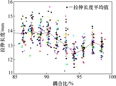
ͼ6��ʾΪ��Ԥ���趨���쳤�ȵ�ʵ���У�ʵ�ʵ����쳤����ʵ����ϱȵ�ӳ���ϵ����ͼ6��֪�������쳤�����ӣ�ʵ����ϱȵ���ɢ�ȳ����������ӵ����ƣ��������ݵ���ɢ���� 1.1%���ӵ�21.1%�������쳤�ȵ�����ʵ����ϱȵ���ɢ������ʵ�����쳤�ȵ���ɢ���� 0.007 mm���Ҳ�����
ͼ6 Ԥ�����쳤��ʱ��ϱ������쳤�ȵĹ�ϵ����ɢ��
Fig. 6 Relationship and deviation of coupling ratio and length under presetting length
ͼ6�У���Ԥ�����쳤��Ϊ12.0~13.0 mmʱ��ʵ�ʵ���ϱȾ�ֵ���ֵ����������۶�Ӧ��ϵ�������ɢ�Ⱥ�С������13.0 mm�Ժ�ʵ����ϱȾ�ֵ�仯���Ʊ仺����������ɢ�ȵ�����Ԥ�����쳤���ڴ���13.8 mm���ִ�����½���
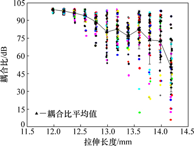
ͼ7��ʾΪͼ6�оֲ�����ķŴ�ͼ����ͼ7�ɼ���Ԥ�����쳤���� 12.0~12.6 mm��仯���Ƚ�С������������״̬�����������Ϊy=177.3-6.5x����Ԥ�����쳤��Ϊ 12.0 mmʱ��ʵ��ƽ�����쳤��Ϊ 11.98 mm����ɢ��Ϊ 0.007 7 mm��ʵ����ϱȾ�ֵΪ99.36%��ʵ����ϱ���ɢ��Ϊ1.13%��ʵ�����쳤����ʵ����ϱȵ���ɢ�ȶ���С��ͼ6�У���Ԥ�����쳤��Ϊ13.0 mmʱ��ƽ�����쳤��Ϊ12.98 mm����ɢ��Ϊ0.006 8 mm��ʵ����ϱȾ�ֵΪ80.29%����ɢ��Ϊ13.29%����Ԥ�����쳤��Ϊ12.0 mmʱ�����ɢ�̶��нϴ�������Ԥ�����쳤��Ϊ13.6 mmʱ��ƽ�����쳤��Ϊ13.58 mm����ɢ��Ϊ0.007 9 mm��ʵ����ϱȾ�ֵΪ82.22%��ʵ����ϱȵ���ɢ��Ϊ16.3%����Ԥ�����쳤��Ϊ13.0 mmʱ�����ɢ�����нϴ����ӡ���Ԥ�����쳤��Ϊ 14.2 mmʱ��ƽ�����쳤��Ϊ14.18 mm��ʵ�����쳤�ȵ���ɢ��Ϊ0.007 9 mm��ʵ����ϱȾ�ֵΪ50.79%��ʵ����ϱ���ɢ��Ϊ 21.16%����ɢ�ȽϿ�ʼʱ���쳤��Ϊ 12.0 mmʱ����ɢ���нϴ����ӡ�
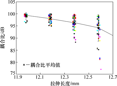
ͼ7 Ԥ�����쳤��ʱ��ϱ������쳤��ӳ���ϵ����ɢ��(���쳤��Ϊ12.0~12.6 mm)
Fig. 7 Relationship and deviation of coupling ratio and length under presetting the length when length is between 12.0 mm and 12.6 mm
3 ����
1) ��Ԥ����ϱ���Ϊ��ֹͣ��ʱ���ڵ�1����������ڣ�ʵ�����쳤�ȵ���ɢ��С�� 0.5 mm��
2) ��Ԥ�����쳤����Ϊ��ֹͣ�������£��������쳤�ȵ����ӣ�ʵ����ϱȵ���ɢ����1.13%���ӵ�21.16%�������쳤��Ϊ12.0~12.6 mm��ʵ����ϱ�y���������쳤��x�����1�����Թ�ϵ����y=177.3-6.5x��
�ο����ף�
[1] ���·, ¦����. ���������������ĵ�ʵ���о�[J]. ����ӡ�����, 2010, 21(10): 1459-1461.
LI Huanlu, LOU Shuqin. Experimental study on the loss of the fused tapered optical fiber couple[J]. Journal of Optoelectronics. Laser, 2010, 21(10): 1459-1461.
[2] �ν���, ������. ���͵�ģ�����������һ����ģ��[J]. �뵼����, 2011, 32(1): 18-23.
REN Jianguo, HU Yongming. A united model of fused single-mode fiber coupler[J]. Semiconductor Optoelectronics, 2011, 32(1): 18-23.
[3] PAL B P, CHAUDHURI P R, SHENOY M R. Fabrication and modeling of fused biconical tapered fiber couplers[J]. Fiber and Inte-grated Optics, 2003, 22(2): 97-117.
[4] �����, ֣��, ������, ��. ���ͱ�ƫ������������ϵ������[J]. �����Ƽ���ѧѧ��, 2007, 29(2): 292-295.
WANG jine, ZHENG Yu, WU Yulie, et al. Coupling coefficient analysis of fused polarization-maintaining fiber couplers[J]. Journal of National University of Defense Technology, 2007, 29(2): 292-295.
[5] HSU C M, SU C T, LIAO D. A novel approach for optimizing the optical performance of the broadband tap coupler[J]. International Journal of Systems Science, 2003, 34(3): 215-220.
[6] WONG W Y, CHOY L K. The manufacturing of an optical fiber coupler by the fusion elongation method[J]. Journal of Materials Processing Technology, 1997, 63(1): 301-310.
[7] YOKOHAMA I, OKAMOTO K. Fiber-coupler fabrication with automatic fusion-elongation processes for low excess loss and high coupling-ratio accuracy[J]. Journal of Lightwave Technology, 1987, 5(7): 910-915.
[8] TAKEUCHI Y, NODA J. Novel fiber coupler tapering process using a microheater[J]. Photonics Technology Letters, IEEE, 1992, 4(5): 465-467.
[9] TIMOTHY E D, GEORGE K, TIMOTHY A B. Carbon dioxide laser fabrication of fused-fiber couplers and tapers[J]. Applied Optics, 1999, 33(38): 6845-6848.
[10] BAYLE F, MEUNIER J P. Efficient fabrication of fused-fiber biconical taper structures by a scanned CO2 laser beam technique[J]. Applied Optics, 2005, 44(30): 6405-6411.
[11] ���·, ¦����. �����������������״������ĵ�Ӱ��[J]. �����뼤���, 2009, 38(S11): 292-295.
LI Huanlu, LOU Shuqin. Experimental study on the relationship between profile and loss of fused tapered optical fibre coupler[J]. Infrared and Laser Engineering, 2009, 38(S11): 292-295.
[12] �ľ�, ��Ծ��. ����������������״���Ե��о�[J]. ��ͨ���о�, 2006, 30(6): 17-18.
XIA Juan, ZHU Yuejin. Research on fused taper shape performances in fused tapering process[J]. Study On Optical Communications, 2006, 30(6): 17-18.
[13] HONG Zehua, LI Xinwan, ZHOU Lijie. Coupling characteristics between two conical micro/nano fibers: simulation and experiment[J]. Optics Express, 2011, 19(5): 3854-3861.
[14] YONGMIN J, GILBERTO B, DAVID J. Optical microfiber coupler for broadband single-mode operation[J]. Optics Express, 2009, 17(7): 5273-5278.
[15] LIN Bo, WANG Pengfei, SEMENOVA Y. High sensitivity fiber refractometer based on an optical microfiber coupler[J]. Photonics Technology Letters, IEEE, 2013, 25(3): 228-230.
[16] YUAN Libo, LIU Zhihai, YANG Jun. Bitapered fiber coupling characteristics between single-mode single-core fiber and single-mode multicore fiber[J]. Applied Optics, 2008, 47(18): 3307-3312.
[17] LIU Jianguo, CHENG T H, YEO T Y. Light beam coupling between standard single mode fibers and highly nonlinear photonic crystal fibers based on the fused biconical tapering technique[J]. Optics Express, 2009, 17(5): 3115-3123.
[18] PAL P, KNOX W H. Fabrication and characterization of fused microfiber resonators[J]. Photonics Technology Letters, IEEE, 2009, 21(12): 766-768.
(�༭ �°���)
�ո����ڣ�2016-03-15�������ڣ�2016-05-29
������Ŀ(Foundation item)��������Ȼ��ѧ����������Ŀ(51475479��51075402)���ߵ�ѧУ��ʿ�����������Ŀ(20110162130004)�����Ҹ����о���չ�ƻ�(863�ƻ�)��Ŀ(2012AA040406)������ʡ��Ȼ��ѧ����������Ŀ(14JJ2010)(Projects (51475479; 51075402) supported by the National Science Foundation of China; Project (2012AA040406) supported by the Ph.D. Programs Foundation of Ministry of Education of China; Project (2012AA040406) supported by the National High Technology Research and Development Program of China (863 Program))
ͨ�����ߣ�֣�ϣ������ڣ����¼��ɹ���������װ���������뼼���о���E-mail��zhengyu@csu.edu.cn
ժҪ��Ϊ̽����������������������ϱ������쳤��֮��Ĺ�ϵ��������������ʵ���о�Ԥ����ϱȺ�Ԥ�����쳤����Ϊ��ֹͣ�⣬ʵ����ϱȺ�ʵ�����쳤�ȵķֲ����ɡ��о����������Ԥ����ϱ���Ϊ��ֹͣ�������£�ʵ�����쳤�ȵ���ɢ��С��0.5 mm��Ԥ�����쳤����Ϊ��ֹͣ�������£�����Ԥ�����쳤�ȵ����ӣ�ʵ����ϱȵ���ɢ����1.13%���ӵ�21.16%����Ԥ�����쳤����12.0~12.6 mmʱ��ʵ����ϱ�y���������쳤��x֮��������Թ�ϵy = 177.3-6.5x�����о�Ϊ������������������칤�����豸�ĸĽ����Ż��ṩ�����뼼��������
[1] ���·, ¦����. ���������������ĵ�ʵ���о�[J]. ����ӡ�����, 2010, 21(10): 1459-1461.
[2] �ν���, ������. ���͵�ģ�����������һ����ģ��[J]. �뵼����, 2011, 32(1): 18-23.
[4] �����, ֣��, ������, ��. ���ͱ�ƫ������������ϵ������[J]. �����Ƽ���ѧѧ��, 2007, 29(2): 292-295.
[11] ���·, ¦����. �����������������״������ĵ�Ӱ��[J]. �����뼤���, 2009, 38(S11): 292-295.
[12] �ľ�, ��Ծ��. ����������������״���Ե��о�[J]. ��ͨ���о�, 2006, 30(6): 17-18.
