
J. Cent. South Univ. (2013) 20: 312�C317
DOI: 10.1007/s11771-013-1489-8

Effects of static aeroelasticity on composite wing characteristics under different flight attitudes
HUO Shi-hui(������), YUAN Zhe(Ԭ��), WANG Fu-sheng(������), YUE Zhu-feng(�����)
Advanced Materials Test Center, School of Mechanics and Civil Engineering & Architecture,
Northwestern Polytechnical University, xi��an 710129, China
 Central South University Press and Springer-Verlag Berlin Heidelberg 2013
Abstract:
Composite wing static aeroelasticity was analyzed through a loosely coupled method and the effects on composite wing characteristics under different flight attitudes were presented. Structural analysis and aerodynamic analysis were carried out through finite element method (FEM) software NASTRAN and computational fluid dynamics (CFD) software FLUENT, respectively. Correlative data transfer and mesh regenerate procedure were applied to couple the results of computational structure dynamics (CSD) and CFD. After static aeroelasticity analysis under different flight attitudes, it can be seen that lift increases with the increase of flight speed and the incremental value enlarges gradually in both rigid and elastic wings. Lift presents a linear increment relationship with the increase of attack angle when the flight speed is 0.4Ma or 0.6Ma, but nonlinear increment in elastic wing when flight speed is 0.8Ma. On the effect of aeroelasticity, the maximum of deformation increases with the increase of flight speed and attack angle, and the incremental value decreases with the increase of flight speed while uniform with different attack angles. The results provide a reference for engineering applications.
Key words:
1 Introduction
Aeroelasticity is always the major concern in aircraft design. Aircraft structure is elastic. Elastic deformation, which is the result of initial aerodynamic function, will lead to additional aerodynamic. Additional aerodynamic will lead to a new elastic deformation. Aircraft structure will obtain a balanced state or deform gradually until structural damage happens [1�C4].
Static aeroelasticity which is related to deformation, aerodynamic load distribution and control surface efficiency plays an important role in aircraft design. Many scholars dedicated to research in this field and a lot of aeroelasticity analysis methods were put forward. QIN [5�C6], HADDADPOUR et al [7] and NA et al [8] investigated the aeroelasticity stability of an aircraft wing modeled with an anisotropic composite thin-walled beam. With the development of computation fluid dynamic, a coupled computational fluid dynamics (CFD) and computational structure dynamics (CSD) method for aeroelasticity computation had been adopted widely [9�C16]. KAMAKOTI and SHYY [17], WONG et al [18] and HUO et al [19] studied moving grid computations for CFD. In the data transfer, GOURA et al [20] and SADEGHI and LIU [21] investigated the application of three-dimensional interfaces in aeroelasticity computation. JOSPH et al [22], MA et al [23], SHI et al [24] and CHEN et al [25] studied the structure response to the effect of aeroelasticity.
Combination of high-precision CFD and CSD software for aeroelasticity problem is an effective method. In the present work, static aeroelasticity is analyzed based on CFD and CSD software and effects on the composite wing characteristics are analyzed.
2 Static aeroelasticity analysis
Static aeroelasticity analysis is an iterative solving process. First of all, aerodynamic calculation of the initial wing model is carried out. The deformation under the function of aerodynamic load above is obtained through structure analysis. Then the mesh for next aerodynamic calculation is regenerated based on deformed wing configuration. Structural analysis is carried out again until both aerodynamic load and deformation are convergent. Here static aeroelasticity parameters including aerodynamic and structural characteristics are obtained.
There are two basic method, loosely coupled method and fully coupled method, in static aeroelasticity analysis. In loosely coupled method, the solving processes of aerodynamic equation and structural equation are independent. It is just data transfer process that need to be considered in loosely coupled method while the whole aerodynamic and structural equations need to be solved together in fully coupled method. Computational efficiency is a key problem for fully coupled method. Loosely coupled method is adopted in the present work. Figure 1 shows the computation process of loosely coupled method.
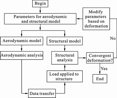
Fig. 1 Loosely coupled method in computation process
2.1 Analysis procedure
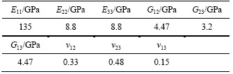
In aerodynamic model, grid on wing plane is dense and extra intensive treatment on leading and trailing edges, while uniform three-node or four-node grids are adopted widely in structural model. The finite element structural model includes 2941 Quad elements and 140 Tri elements. Figures 2 and 3 show the wing plane grid of aerodynamic and structural analysis, respectively. The wing is mainly composed of skin, lengthwise and transverse components. Lengthwise components include spar and stringer while transverse components include rib and thin-walled jointed structure. Skin, spar and stringer are made of composite material T300/QY8911. Its material properties are given in Table 1. Rib is made of titanium alloy. Its elastic modulus is 135 GPa, and Poisson ratio is 0.3.
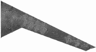
Fig. 2 Wing plane grid of aerodynamic analysis
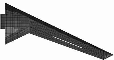
Fig. 3 Grid of structural analysis
Table 1 Material properties of T300/QY8911
CFD software FLUENT is adopted for aerodynamic analysis while FEM software NASTRAN for structural analysis. Pressure distribution on the coupled surface can be obtained through aerodynamic analysis, but load for structural analysis often needs to be applied directly on structural nodes or elements. The locations of node and element are different in these two models. So data transfer is necessary. Pressure distribution of wing plane is extracted from FLUENT computational results firstly. Three directions compression force of CFD nodes can be obtained through
 (1)
(1)
where Gx, Gy and Gz are compression forces in three directions, S is the applied area of pressure P, nx ny and nz are normal vectors of coupled surface in three directions, respectively. For each CFD node, three CSD nodes surrounding it with the smallest area are selected. Each CSD node is associated with several CFD nodes. The ultimate load information of CSD node is the combination of correlative CFD nodes data transfer results. It can be written as
 (2)
(2)
where F is the ultimate load of CSD node,  is the transferred load of each CFD node. can be obtained through
 (3)
(3)
where Fx, i, Fy, i and Fz, i are load applied on structure, Ai and A are areas of two triangles, the former is formed by one CFD node and two CSD nodes while the latter is formed by three CSD nodes.
Structural analysis is carried out through software NASTRAN. Flow field mesh for next aerodynamic analysis is generated based on the deformed wing configuration. Mesh regeneration method is adopted in the present work. Model building and mesh generating are carried out through preprocessing software GAMBIT. As shown in Fig. 4, ten characteristic lines are selected based on the changing of wing configuration. A number of coordinates of index points are obtained based on the initial coordinates and deformation. Wing configuration is regenerated through fitting the characteristic lines. Aerodynamic mesh generating is carried out through GAMBIT too. Iterative computation is performed until both aerodynamic force and deformation are convergent.
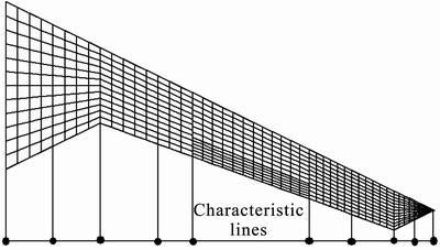
Fig. 4 Characteristic lines of wing
2.2 Static aeroelasticity results
Static aeroelasticity of the wing is analyzed under the flight attitude of 0.6Ma and attack angle of 1.12��. After being iterated nine times, deformation and lift are convergent. The deformation converges at 230.14 mm while lift converges at 2 650.17 N. Figures 5 and 6 show deformation and torsion angle of cross section. It can be seen from Fig. 5 that deformation of wing root which is restrained is 0 mm while wing tip has the maximum deformation. Intermediate section deforms glossily. Unfortunately, torsion angle of cross section is not so regular. It can be seen from Fig. 6 that torsion angle of cross section convexes and glossily increases with the increase of nondimensional span before 38% of span. Then a nearly linear increment happens at a range from 38% to 76% of span, which is caused by aileron. Finally, torsion angle drives to smooth and reaches its maximum value. Torsion angle of the wing reduces practical attack angle. It leads to the decrease of lift.
3 Effects on aerodynamic characteristics
The lifts of rigid and elastic wing under different flight attitudes are analyzed. Figure 7 shows the
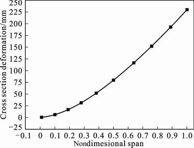
Fig. 5 Deformation of cross section
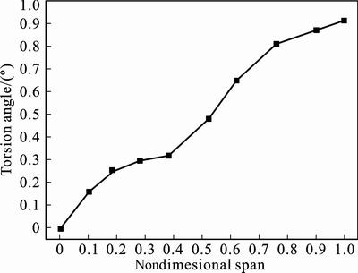
Fig. 6 Torsion angle of cross section
changing of lift with the increase of flight speed at different attack angles. It can be seen from Fig. 7 that lift of elastic wing is obviously less than that of rigid wing under the same flight attitude. It is caused by static aeroelasticity, which leads to a wing cross section torsion. Lift increases with the increase of flight speed and the incremental value enlarges gradually, which shows the same trend in both rigid and elastic wings. Figure 8 shows the changing of lift with increase of attack angle under different flight speeds. It can be seen from Fig. 8 that lift of elastic wing is obviously less than that of rigid wing under the same flight attitude. In rigid wing, lift shows a linear increment with the increase of attack angle, which has the same conclusion at 0.4Ma, 0.6Ma and 0.8Ma. But in elastic wing, lift shows a nearly linear increment with the increase of attack angle at 0.4Ma and 0.6Ma while it is nonlinear in 0.8Ma. It is because that, when the flight speed is 0.8Ma, air flow speed which is influenced by elastic deformation maybe larger than 0.8Ma, which leads to a nonlinear relationship.
4 Effects on structural characteristics
Cross section deformations under different flight
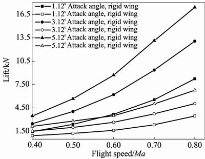
Fig. 7 Lift with increase of flight speed under different attack angles
Fig. 8 Lift with increase of attack angle under different flight speeds
attitudes are shown in Figs. 9�C14. Figures 9�C11 show cross section deformation under different flight speeds when attack angle keeps at 1.12��, 3.12�� and 5.12��, respectively. It can be seen from Figs. 9�C11 that deformation of wing root is 0 mm while wing tip has the maximum deformation. The maximum deformation increases with the increase of flight speed, but the incremental value decreases with the increase of flight speed.
Figures 12�C14 show cross section deformation under different attack angles when flight speed keeps at 0.4Ma, 0.6Ma and 0.8Ma, respectively. It can be seen from Figs. 12�C14 that deformation of wing root is 0 mm while wing tip has the maximum deformation too. The maximum deformation increases with the increase of attack angle, but the incremental value is uniform, which is different from above. This is because that all the attack angles discussed are below stall speed. Lift shows a linear increase with the increase of attack angle, which leads to a uniform value of maximum deformation increment.
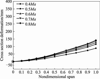
Fig. 9 Cross section deformation under different flight speeds and attack angle of 1.12��
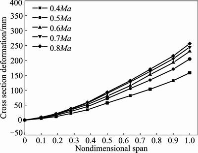
Fig. 10 Cross section deformation under different flight speeds and attack angle of 3.12��
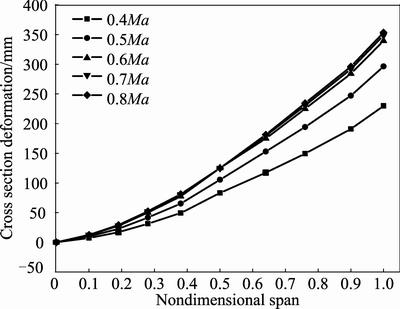
Fig. 11 Cross section deformation under different flight speeds and attack angle of 5.12��
Cross section deformation of elastic wing increases with the increase of flight speed and attack angle. But uniform incremental value keeps with the increase of attack angle while gradually reduces incremental value with the increase of flight speed.
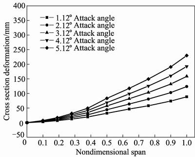
Fig. 12 Cross section deformation under different attack angles and 0.4Ma
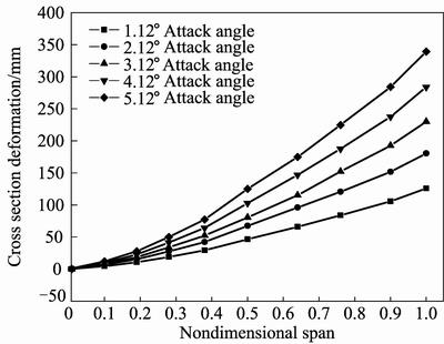
Fig. 13 Cross section deformation under different attack angles and 0.6Ma
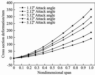
Fig. 14 Cross section deformation under different attack angles and 0.8Ma
5 Conclusions
1) Lift of elastic wing is obviously less than that of rigid wing under the same flight attitude. It is caused by static aeroelasticity which leads to a wing cross section torsion and decreases practical attack angle.
2) Lift increases with the increase of flight speed and the incremental value enlarges gradually, which shows the same trend in both rigid and elastic wings.
3) Lift presents a linear increment relationship with the increase of attack angle in both rigid and elastic wings when the flight speed is 0.4Ma or 0.6Ma, while nonlinear increment in elastic wing when the flight speed is 0.8Ma.
4) On the effect of aeroelasticity, deformation of wing root is 0 mm while wing tip has the maximum value. The maximum deformation increases with the increase of flight speed and attack angle, and the incremental value decreases with the increase of flight speed while uniform with different attack angles.
Reference
[1] PALACIOS R, CESNIK C. Static nonlinear aeroelasticity of flexible slender wings in compressible flow [J]. AIAA Paper, 2005, AIAA-2005-1945.
[2] AHREM R, BECKERT A, WENDLAND H. Recovering rotations in aeroelasticity [J]. Journal of Fluids and Structures, 2007, 23(6): 874�C884.
[3] SVACEK P. Application of finite element method in aeroelasticity [J]. Journal of Computational and Applied Mathematics, 2008, 215(2): 586�C594.
[4] ATTORNI A, CAVAGNA L, QUARANTA G. Aircraft T-tail flutter predictions using computational fluid dynamics [J]. Journal of Fluids and Structures, 2011, 27(2): 161�C174.
[5] QIN Z. Vibration and aeroelasticity of advanced aircraft wings modeled as thin-walled beams �C dynamics, stability and control [D]. Blacksburg: Virginia Polytechnic Institute and State University, 2001.
[6] QIN Z, LIBRESCU L. Aeroelastic instability of aircraft wings modeled as anisotropic composite thin-walled beams in incompressible flow [J]. Journal of Fluids and Structures, 2003, 18(1): 43�C61.
[7] HADDADPOUR H, KOUCHAKZADEH M A, SHADMEHRI F. Aeroelastic instability of aircraft composite wings in an incompressible flow [J]. Composite Structures, 2008, 83(1): 93�C99.
[8] NA S, SONG J, CHOO J H, QIN Zhan-ming. Dynamic aeroelastic response and active control of composite thin-walled beam structures in compressible flow [J]. Journal of Sound and Vibration, 2011, 330(5): 4998�C5013.
[9] SMITH M J, HODGES D H, CESNIK C E S. Evaluation of computational algorithms suitable for fluid-structure interactions [J]. Journal of Aircraft, 2000, 37(2): 282�C294.
[10] DOWELL E H, HALL K C. Modeling of fluid-structure interaction [J]. Annual Review of Fluid Mechanics, 2001, 33(1): 445�C490.
[11] CAI J, LIU F, TSAI H M. Static aero-elastic computation with a coupled CFD and CSD method [J]. AIAA Paper, 2001, AIAA�C2001�C0717.
[12] KAMAKOTI R, SHYY W. Fluid-structure interaction for aeroelastic applications [J]. Progress in Aerospace Sciences, 2004, 40(8): 535�C558.
[13] GURUSWAMY G. A new modular approach for tightly coupled fluid/structure analysis [J]. AIAA Paper, 2004, AIAA�C2004�C4547.
[14] DANG Hui-xue, YANG Zhi-chun, LI Yi. Accelerated loosely-coupled CFD/CSD method for nonlinear static aeroelasticity analysis [J]. Aerospace Science and Technology, 2010, 14(4): 250�C258.
[15] SHYY W, AONO H, CHIMAKURTHI S K. Recent progress in flapping wing aerodynamic and aeroelasticity [J]. Progress in Aerospace Sciences, 2010, 46(7): 284�C327.
[16] DEMASI L, LIVNE E. Aeroelastic coupling of geometrically nonlinear structures and linear unsteady aerodynamics: two formulations [J]. Journal of Fluids and Structures, 2009, 25(5): 918�C935.
[17] KAMAKOTI R, SHYY W. Moving grid computations for turbulent, aeroelastic flows [J]. AIAA Paper, 2003, AIAA�C2003�C3719.
[18] WONG A, TSAI H, CAI J, ZHU Y, LIU F. Unsteady flow calculations with a moving mesh algorithm [J]. AIAA Paper, 2000, AIAA�C2000�C1002.
[19] HUO Shi-hui, WANG Fu-sheng, YAN Wu-zhu, YUE Zhu-feng.
Layered elastic solid method for the generation of unstructured dynamic mesh [J]. Finite Element in Analysis and Design, 2010, 46(10): 949�C955.
[20] GOURA G S L, BADCOCK K J, WOODGATE M A. A data exchange method for fluid-structure interaction problems [J]. Journal of Aircraft, 2001, 38(2): 282�C342.
[21] SADEGHI M, LIU F. Application of three-dimensional interfaces for data transfer in aero-elastic computations [J]. AIAA Paper, 2004, AIAA-2004-5376.
[22] JOSEPH A, GARCIA, GURU P G. Static aeroelastic characteristics of an advanced wing with a control surface using navier-stokes equations [J]. AIAA Paper, AIAA�C1999�C0796, 1999.
[23] MA Tie-lin, MA Dong-li, ZHANG Hua. Aerodynamic characteristic analysis of high-aspect ratio elastic wing [J]. Journal of Beijing University of Aeronautics and Astronautics, 2007, 33(7): 781�C784.
[24] SHI Ai-ming, YANG Yong-nian, WANG Gang. Investigations of characteristics of static aeroelasticity for elastic wing in transonic flow [J]. Engineering Mechanics, 2006, 23(5): 173�C176.
[25] CHEN Zhi-min, XU M, CHEN Shi-lu. An analysis of structure response for transonic static aeroelasticity [J]. Journal of Air Force Engineering University, 2005, 6(1): 1�C4.
(Edited by HE Yun-bin)
Foundation item: Project(50905142) supported by the National Natural Science Foundation of China; Project(2009JQ1006) supported by the Natural Science Foundation of shaanxi province, China
Received date: 2012�C04�C16; Accepted date: 2012�C12�C16
Corresponding author: HUO Shi-hui, PhD; Tel: +86�C29�C88431002; E-mail: hshxin1985@163.com
Abstract: Composite wing static aeroelasticity was analyzed through a loosely coupled method and the effects on composite wing characteristics under different flight attitudes were presented. Structural analysis and aerodynamic analysis were carried out through finite element method (FEM) software NASTRAN and computational fluid dynamics (CFD) software FLUENT, respectively. Correlative data transfer and mesh regenerate procedure were applied to couple the results of computational structure dynamics (CSD) and CFD. After static aeroelasticity analysis under different flight attitudes, it can be seen that lift increases with the increase of flight speed and the incremental value enlarges gradually in both rigid and elastic wings. Lift presents a linear increment relationship with the increase of attack angle when the flight speed is 0.4Ma or 0.6Ma, but nonlinear increment in elastic wing when flight speed is 0.8Ma. On the effect of aeroelasticity, the maximum of deformation increases with the increase of flight speed and attack angle, and the incremental value decreases with the increase of flight speed while uniform with different attack angles. The results provide a reference for engineering applications.
