

Influence of load on sliding tribology of C/C composite with
40Cr steel couple coated by Cr
GE Yi-cheng(�����), YI Mao-zhong(���), LI Li-ya(�����)
State Key Laboratory for Powder Metallurgy, Central South University, Changsha 410083, China
Received 8 September 2006; accepted 10 January 2007
Abstract:
With the 40Cr steel couple coated by Cr, the sliding tribology behavior of two kinds of C/C composites with different matrix was tested using a M2000 wear tester. The results show that with the increasing of load, the friction coefficients of the composite with resin carbon matrix(RC) decrease quickly from 0.156 under 60 N to 0.123 under 150 N, while those of the composite with rough lamination/smooth lamination /resin carbon (RL/SL/RC) change only between 0.122 and 0.101. The wear volume loss of the two composites increases except for under 100 N. The SEM morphology shows that with the increasing of load, the worn surface of the composite with RC becomes more and more integrated while the size of the debris becomes less and less. The Raman spectrum shows that the graphitization on the worn surface of the fibers draws down after 100 N, the graphitization of the boundary between the fiber and the matrix carbon rises up to 150 N, but the graphitization of the matrix carbon draws down all the while. With the increasing of load, the graphitization on the worn surface of all the worn areas becomes closer and closer, which indicates the worn surface of the different component has the similar friction ability. The composites with RL/SL/RC have better tribological characteristic than the composite with RC.
Key words:
C/C composite; sliding tribology; load; 40Cr steel;
1 Introduction
Recently, the C/C composite has been widely used in the field of airplane brake system due to its high strength, high module, high thermal conductivity, low density, low heat expansion coefficient and excellent self-lubrication properties[1-4]. And now C/C composite has become one of the suitable materials used as seal ring of the main axis of aero-engine[5]. However, most researches were only focused on the braking tribology behavior using C/C composite couple, such as the influence of the fiber types and the perform[2,6], the matrix carbon structure [7-10], the graphitization[8,11], sample geometry[12], worn surface morphologies[7,13], gas[14], contact energy[6-8,14-15] and temperature[15]. It was found that the C/C composites with rough lamination pyrocarbon matrix have excellent tribology properties and are the proper materials used as braking material. But when they were used as a seal ring with some steel couples, the braking tribology does not agree with that of the continuously sliding tribology behavior. Some studies showed that the proper matrix carbon of the C/C used as seal ring might be the rough lamination/smooth lamination/resin carbon, which was different from the braking materials[16].
Since the testing load is one of the important factors influencing the sliding tribology behavior of C/C composites[2,5,7], this study investigated the influence of the load.
2 Experimental
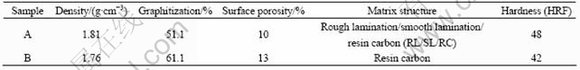
Two types of C/C composites were made from a three-dimensional needled carbon fiber preform, which was fabricated by needling the stack of alternating layers of unidirectional non-woven carbon cloth and carbon felt made from chopped fibers. One composite was densified by chemical vapor infiltration (CVI) in C3H6+N2 atmosphere to the density of 1.5 g/cm3 at first and then by the impregnation and carbonization of furan resin, the other was densified only by the impregnation and carbo- nization of furan resin. The volume fraction of carbon fibers in the materials was 33%. The specimens were finally heat treated at 2 100 ��. The optical micro- structures were observed with an inverse microscope with Nicols polarizer. The graphitization degree and LC were measured with X-ray diffractometer. The hardness was measured with HD9-45 apparatus using a steel ball with the diameter of 1.588 mm. The properties of the C/C composites are listed in Table 1.
Table 1 Properties of C/C composite specimens
The wear test was conducted on a M2000 tester in air at room temperature without lubrication. The test machine held a rotor ring and a stator block. Block specimens for the friction testing were C/C composite with the size of 20 mm��12 mm��6 mm and the wear surface was 20 mm��12 mm. Prior to testing, all samples were mechanically polished to 1200# grit level, followed by ultrasonic cleaning to remove debris on surface. The couple was 40Cr steel coated by Cr with the size of d (40-16) mm��10 mm. The testing loads were 60, 80, 100, 120 and 150 N, respectively. The linear speed between the couples was 0.42 m/s.
The morphology of wear surface was observed with a JSM-35C SEM apparatus. The change of the graphitization on the worn surface was measured with a RM2000 Raman spectroscopy apparatus. The breadth of grinding marks was measured by a MeF3A optical microscope to calculate the bulk wear loss.
3 Results and discussion
3.1 Wear test
Fig.1 shows the results of wear test of the two composites under different testing loads. As shown in Fig.1(a), the friction coefficient of composite A draws down at first and then rises between 80-120 N and draws down at last, but the friction coefficient of composite B draws down quickly at first and then remains stable up to 150 N; under any load, the friction coefficient of composite A has lower value and changing extent than that of composite B. The volume loss of composite A is also lower than that of composite B under all loads (Fig.1(b)), but the volume loss of the two composites has the similar change trend. The results indicate that composite A has better tribological characteristic than composite B.
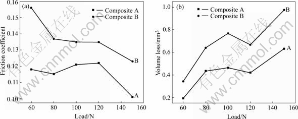
Fig.1 Friction coefficient (a) and volume loss (b) of two C/C composites under different loads
The friction coefficients of the two composites under different loads with the increasing of time are shown in Fig.2. It shows that the friction coefficients of composite A remain stable after 1 h test (Fig.2(a)), but those of composite B remain the similar decreasing trend after 1 h test. Since the friction coefficients of composite A can reach stability more quickly and have lower changing extent than those of composite B, which indicates again that composite A has better tribological characteristic.
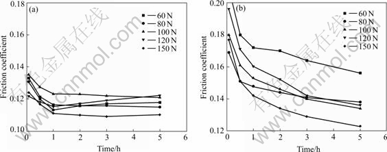
Fig.2 Friction coefficients of composites A (a) and B (b) with time under different loads
3.2 SEM and Raman spectroscopy analysis
The SEM morphologies of the worn surface of composite B under 60 N and 150 N are shown in Fig.3. As shown in Fig.3(a), three types of worn morphology are found on the worn surface after the test under 60 N. The first type is black surface composed of some smooth friction film and some fibers without integrated friction film. The second type is the right surface composed of the smooth debris film with large cracks. The third type is the debris loosely piled. Large grinding cracks exist on the integrated friction film in Fig.3(b). After the test under 150 N, two types of worn surface are found in Fig.3(c). One is the black, integrated surface with grinding cracks and large cracks; the other is the right, smooth and integrated debris film. Many fiber tips exist on the worn surface without thick debris film covered (Fig.3(d)), which indicates that the surface is worn more seriously than that under low load.
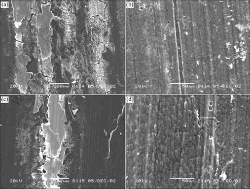
Fig.3 SEM morphologies of worn surface after test under 60 N ((a), (b)) and 150 N((c), (d)), respectively
Typical morphologies of the debris under different loads of composite B are demonstrated in Fig.4. As shown in Fig.4(a), the debris under 60 N have sheet or particles-gathering morphologies; a multi-layer piled debris film exist on the edge of the friction film. The reason is that some debris are moved and piled up on the edge of the friction film because they can not form the debris film quickly under low load, after the debris piled on the edge are enough, the integrated friction film forms slowly. And then others debris pile up and form the film on the edge again. Under 100 N, the debris have the particle shape (Fig.4(b)). Under 150 N, the debris also have the particle shape with the least in the quantity among the three morphologies (Fig.4(c)).
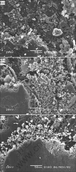
Fig.4 SEM morphologies of debris of composite B under 60 N (a), 100 N (b) and 150 N (c), respectively
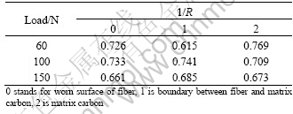
In Raman spectroscopy of carbon material, there exist two main peaks that are at 1 333.49 cm-1 (ID) and 1 584.16 cm-1 (IG) corresponding to turbostratic carbon and graphitoid carbon, respectively. The IG/ID ratio (1/R) can indicate the change of graphitization on the surface layer[15]. Table 2 displays the 1/R on the worn surface of the different components of composite B after the test under different loads. It is shown that with the increasing of load, the 1/R on the worn surface of the fiber remains stable up to 150 N, which means the graphitization remains stable up to 150 N, those of the boundary between the matrix and the fibers rise up to 150 N, but those of the matrix carbon drown down all the while.The difference of the 1/R of the different worn surfaces is reduced with the increasing of load, which indicates that the worn surfaces of the different components have the similar friction characteristic.
Table 2 1/R on different wear surfaces of composite B after test under different loads
3.3 Discussion
With the increasing of load, more particles on the worn surface contact with the couple, and the deformation of the particles increases, which increases the real contact areas; and during the ring-block sliding test, the contact form between the couples changes from linear contact to face contact, which increases the real contact area and forms integrated film, so the friction coefficient is reduced.
The debris from the matrix carbon is easy to form the integrated friction film under low load, but the debris from the fibers is difficult to be crashed and is easy to destroy the friction film, which makes the worn surface rough. Under high-test load, most debris are easy to form the friction film that decreases the friction coefficient. With the increasing of time, the changing extent of friction coefficients under high load is lower than that under low load, which indicates that the real contact area and the frictional force of the friction film are the main factors influencing the friction coefficient.
Since the matrix has high graphitization and low hardness, the worn surface is easy to be destroyed under all test loads, which leads to the 1/R decrease all the while with the increasing of load. For the fibers, the 1/R remains stable until 150 N. The reason is that the worn surface of the fibers is covered by some debris moved from the matrix and the debris forms the integrated film under low and middle loads, so the 1/R remains high value. But under high load, both the matrix debris and the fiber are worn seriously, which decreases the arrangement of the graphite micro-crystal on the wear surface of the fiber quickly, so the 1/R decreases. For the boundary, the main factor is the impacted degree of the debris filled in the boundary. Under low load, the debris is not smashed enough to form the integrated film with regular-arrangement graphite micro-crystals, which makes it have the lowest 1/R among the three types surface. With the increasing of load, the debris filled in the boundary is impacted tightly and forms the integrated film, so the 1/R increases. But under high load, such film is destroyed seriously and the 1/R decreases again.
With the increasing of load, the debris from different components is smashed and mixed and distributed equably on the surface, so the difference of the debris and the 1/R of different worn surfaces decreases.
Since the RL/SL/RC matrix has high hardness and good wearability to form integrated and compacted friction film[5,16-17], composite A with RL/SL/RC has better friction characteristic than composite B with RC matrix.
4 Conclusions
With 40Cr steel coated by Cr as couple, the friction coefficient of the composite with RC draws down quickly from 0.156 under 60 N to 0.123 under 150 N, while that of the composite with RL/SL/RC only changes between 0.122 and 0.101. The volume loss of the two composites increases except for that under 100 N. With the increasing of time, the change extent of friction coefficients under high load is lower than that under low load. The SEM morphology shows that with the increasing of load, the worn surface of the composite with RC becomes more and more integrated while the size of the debris becomes less and less. The results of Raman spectroscopy analysis indicate that with the increasing of load, the graphitization of the fibers decreases after 100 N, and that of the boundary between the fiber and the matrix carbon increases up to 150 N, but that of the matrix carbon decreases all the while. The graphitization of the different worn surface becomes closer and closer, which indicates that all the worn surfaces have the similar friction ability. Since the composite with RL/SL/RC has less friction coefficient and less volume loss than the composite with RC under all testing loads, it is a proper material to be used as seal ring.
References[1] YUAN Yi-dong, LUO Rui-ying, ZHANG Fu-kuan, LI Jin-song, LIU Tao, ZHOU Wan-cheng. Influence of high temperature heat treatment on the friction properties of carbon/carbon composites under wet conditions [J]. Materials Science and Engineering A, 2005, 402: 203-207.
[2] MOHAMED S, ALY-HASSAN, HIROSHI H. Comparison of 2D and 3D carbon/carbon composites with respect to damage and fracture resistance [J]. Carbon, 2003, 41(5): 1069-1078.
[3] GUSTIN J, JONESON A, MAHINFALAH M. Low velocity impact of combination Kevlar/carbon fiber sandwich composites [J]. Composite Structures, 2005, 69: 396-406.
[4] OZTURK A. The influence of cyclic fatigue damage on the fracture toughness of carbon-carbon composites [J]. Composites (Part A), 1996, 27: 641-646.
[5] GE Yi-cheng, YI Mao-zhong. Influence of load, time, speed on sliding tribology behavior of C/C composites [J]. The Chinese Journal of Nonferrous Metals, 2006, 16(2): 241-246. (in Chinese)
[6] ZHANG Zhao-zhu, SU Feng-hua, WANG Kun. Study on the friction and wear properties of carbon fabric composites reinforced with micro- and nano-particles [J]. Materials Science and Engineering A, 2005, 404: 251-258.
[7] YEN B K, ISHIHARA T. The surface and morphology and structure of carbon-carbon composites in high-energy sliding contact [J]. Wear, 1994, 174: 111-117.
[8] GUELLALI M, OBERACKER R, HOFFMANN M J. Influence of the matrix microstructure on the mechanical properties of CVI-infiltrated carbon fiber felts [J]. Carbon, 2005, 43(7): 1954-1960.
[9] XIONG Xiang, HUANG Bai-yun, YI Jiang-hong, XU Hui-juan. Friction behaviors of carbon/carbon composites with different pyrolytic carbon textures [J]. Carbon, 2006, 44(3): 463-467.
[10] SHIN H K, LEE H B, KIM K S. Tribological properties of pitch-based 2-D carbon-carbon composites [J]. Carbon, 2001,39(5): 959-970.
[11] ZOU Lin-hua, HUANG Bai-yun, HUANG Yong, HUANG Qi-zhong, WANG Chang-an. An investigation of heterogeneity of the degree of graphitization in carbon-carbon composites [J]. Materials Chemistry and Physics, 2003, 82: 654-662.
[12] VENKATARAMAN B, SUNDARARAJAN G. The influence of sample geometry on the friction behaviour of carbon-carbon composites [J]. Acta Materialia, 2002, 50: 1153-1163.
[13] LEE K J, CHERN J H, JU C P. Surface effect on braking behavior of PAN-pitch carbon-carbon composites [J]. Wear, 1996, 199: 228-236.
[14] YEN B K. Influence of water vapor and oxygen on the tribologyof carbon materials with sp2 valence configuration [J]. Wear, 1996, 192: 208-215.
[15] YEN B K, ISHIHARA T. On the temperature-dependant tribological regimes and oxidation of carbon-carbon composites up to 1 800 �� [J]. Wear, 1996, 196: 254-262.
[16] YI Mao-zhong, GE Yi-cheng, HUANG Bai-yun. Charasteristics of wear surface morphology and wear mechanism of C/C composite with different matrix carbon [J]. The Chinese Journal of Nonferrous Metals, 2006, 16(6): 929-936. (in Chinese)
[17] GE Yi-cheng, YI Mao-zhong. Influence of carbon matrix on the tribology of C/C composites used as shaft sealing ring [J]. Acta Aeronautica Et Astronautica Sinica, 2004, 25(6): 619-624. (in Chinese)
Foundation item: Project(2006CB600906) supported by the National Basic Research Program of China
Corresponding author: YI Mao-zhong; Tel: +86-731-8830894; E-mail: yimaozhong@126.com
Abstract: With the 40Cr steel couple coated by Cr, the sliding tribology behavior of two kinds of C/C composites with different matrix was tested using a M2000 wear tester. The results show that with the increasing of load, the friction coefficients of the composite with resin carbon matrix(RC) decrease quickly from 0.156 under 60 N to 0.123 under 150 N, while those of the composite with rough lamination/smooth lamination /resin carbon (RL/SL/RC) change only between 0.122 and 0.101. The wear volume loss of the two composites increases except for under 100 N. The SEM morphology shows that with the increasing of load, the worn surface of the composite with RC becomes more and more integrated while the size of the debris becomes less and less. The Raman spectrum shows that the graphitization on the worn surface of the fibers draws down after 100 N, the graphitization of the boundary between the fiber and the matrix carbon rises up to 150 N, but the graphitization of the matrix carbon draws down all the while. With the increasing of load, the graphitization on the worn surface of all the worn areas becomes closer and closer, which indicates the worn surface of the different component has the similar friction ability. The composites with RL/SL/RC have better tribological characteristic than the composite with RC.
