
Trans. Nonferrous Met. Soc. China 29(2019) 1889-1902
Fabrication, microstructure, friction and wear properties of SiC3D/Al brake disc-graphite/SiC pad tribo-couple for high-speed train
Lan JIANG1,2, Yan-li JIANG3, Liang YU3, Hong-liang YANG1,2, Zi-shen LI1,2, You-dong DING1,2, Gao-feng FU1,2
1. Key Laboratory for Ecological Metallurgy of Multimetallic Mineral (Ministry of Education), Northeastern University, Shenyang 110819, China;
2. School of Metallurgy, Northeastern University, Shenyang 110819, China;
3. Key Laboratory of New Processing Technology for Nonferrous Metals & Materials, Ministry of Education, Guilin University of Technology, Guilin 541004, China
Received 18 September 2018; accepted 16 July 2019
Abstract:
The friction and wear properties of interpenetrating phase composites (IPC) SiC3D/Al sliding against graphite/SiC (G/SiC) composites were investigated using a sub-scale brake dynamometer. The testing conditions included a braking pressure of 1.25 MPa and an initial braking speed (IBS) of 200-350 km/h in a braking process of high-speed train according to the scale-conversion rules. The tribo-couple materials were characterized using scanning electron microscopy (SEM), X-ray diffractometry (XRD), and energy-dispersive X-ray spectrometry (EDS). It is found that the matching tribo-couple features low friction surface temperature, reliable friction factor, and high durability. The continuous lubricating mechanically-mixed layer (MML) forms gradually on the worn surfaces of ring in the friction process. The MML is heterogeneous, which greatly controls wear rate and coefficient of friction (COF) of the composites. The wear mechanism of SiC3D/Al is typically abrasive wear at an IBS of 200-300 km/h. When the IBS increases to 350 km/h, oxidation wear and delamination are observed. The friction behavior of the tribo-couple predicted using Solidwork simulation software agrees well with the experimental results. The tribo-couple meets the requirement of emergency braking of high-speed train.
Key words:
SiC3D/Al; graphite/SiC; tribo-couple; wear; microstructure; sub-scale brake test;
1 Introduction
A tribo-couple is comprised of a brake disc and a friction pad, and functions as an energy converter transforming kinetic energy of vehicle into heat energy [1]. About 95% of the braking heat energy is absorbed by the brake disc, which causes serious problems such as hot band, hot spot, thermal plastic deformation, friction stability, and thermal mechanical fatigue [2]. Aluminum metal-matrix composite (Al- MMCs) brake discs instead of the cast iron (steel) brake discs have been investigated for many years with the aim of saving energy consumption and maintaining a good dry friction and wear performance when being applied to the high-speed trains (HSTs) [3-5]. The SiC3D/Al alloy composites are one of the new types of Al-MMCs, which consist of two interpenetrating continuous topological networks, one being Al alloy and the other SiC reticulated porosity ceramics (SiC RPCs) [6]. SiC3D/Al composite materials have many advantages such as low density [7], large toughness [8], little fragility [9], and high thermal conductivity [10]. The SiC3D/Al composites reinforced by SiC RPCs have better tribology properties than SiCp/Al composites containing the same content of particles reinforcement, since SiC RPCs reinforcement endures the braking pressure and improves the high-temperature capabilities [11].
The pad materials commonly used for HSTs braking system are powder metallurgy materials (PMM) [12], C/C-SiC composites [13], and metal-matrix composites (MMC) [14,15]. These pad materials display many advantages such as stable coefficient of friction (COF), low noise, high thermal conductivity and good running-in characteristics. However, the mismatch between the SiC3D/Al brake disc and the common pads can damage the pads, which greatly reduces the service life of pads. Compared to these pads, carbon/ceramic pads can absorb more friction heat at high sliding speed and withstand greater wear resistance [16]. Graphite/SiC (G/SiC) can develop the friction characteristics, which could be used in dry and wet conditions compared to C/C-SiC pads [17]. The characteristics of the friction materials are determined by their compositions, manufacturing, and operating conditions of the brake. However, limited information is available on the friction behavior between SiC3D/Al disc and G/SiC pad materials up to today. In this study, G/SiC is used as the pad material, and SiC3D/Al as a disc material. G/SiC is aimed to obtain stable physical properties, mechanical properties and good frictional properties of matching tribo-couples under the testing conditions of the braking pressure and initial breaking speed (IBS) in a HST emergency braking process. The sub-scale brake dynamometer friction testing has the potential to reduce/shorten brake system development cost and time [18]. Moreover, the wear behavior was simulated with the finite element (FE) method.
2 Experimental
2.1 Fabrication of brake disc material
SiC RPCs were fabricated by the polymer replica method [19]. The raw materials used for preparing SiC coating slurry were ��-SiC powder (d50<0.3 ��m, purity >98%, ��=3.18 g/cm3, from Tangshan Hexagon Co., Ltd., Hebei Province, China), h-BN powder (d50<2 ��m, purity >98%, ��=2.27 g/cm3, from Yingkou Tianyuan Chemical Research Institute Co., Ltd., Liaoning Province, China), and B4C powder (d50<3 ��m, purity >96%, ��= 2.52 g/cm3, from Mudanjiang Forward Carbide Boron Co., Ltd., Heilongjiang Province, China). Dolapix CE-64 (Zschimmer & Schwarz) was used as the dispersant, polyvinyl alcohol PVA (Guilin Baer Chemical Reagents Co., Ltd., China) as the binder, and sodium carboxymethyl-cellulose CMC (Guilin Baer Chemical Reagents Co., Ltd., China) as the thickening agent. The contents of Dolapix CE-64, CMC and PVA were 2, 0.5, and 0.5 wt.% in SiC slurry, respectively. Aqueous SiC suspensions with about 50 vol.% solid were fabricated by adding the required contents of SiC, h-BN and B4C powders (98, 0.5 and 1.5 wt.%) in distilled water. The additives (Dolapix CE-64, CMC and PVA) were used based on the mass fraction of the solid in the distilled water. The SiC slurry was stirred for 12 h with ball milling processes using a Nylon tank equipped with ZrO2 balls of 10 mm in diameter. The pH of all suspensions was kept at 9-9.8. The polyurethane open-cell sponge templates (15 pores/inch) with dimensions of 200 mm �� 200 mm �� 7.5 mm were immersed into the SiC slurry, followed by passing through preset roller to remove excessive slurry. Remaining closed pores were eliminated by blowing compressed air through the sponge structure. After microwave drying for 15-20 min, the green SiC bodies with reticulated porosity and good handling strength were produced. Black polyurethane sponge was coated by SiC layers of 0.8-1 mm in thickness. After sintering at 2050 ��C for 60 min in a graphite resistor furnace, with argon gas as the sintering atmosphere, the green SiC bodies were sintered to form the SiC RPCs with a shrinkage of 16%. The SiC RPC preforms were heated at 1200 ��C for 2-4 h in a stationary air ambient. The SiC3D/Al composites were fabricated via a low-pressure casting method (LPCM). Molten Al alloy (6.8-7.5 wt.% Si, 1.8-2.3 wt.% Cu, 0.33-0.50 wt.% Mg, 0.15 wt.% Ti, 0.07-0.1 wt.% Fe, 0.003 wt.% Sr, and balance Al) from Youhua Aluminum Group Corporation, Jiangsu Province, China, was cast into the oxidized SiC PRCs using the low-pressure casting equipment (Zhejiang Wanfeng Technology Development Co., Ltd., Zhejiang Province, China). The process of LPCM is shown in Fig. 1. After pouring molten Al alloy into the mold, a max pressure of 0.25 MPa was applied on the molten Al alloy for infiltration. The SiC RPC preforms were attached to the bottom of the hot-working die steel mold. The preheating temperature of the preforms and the mold was 400-500 ��C. Molten Al alloy of about 700 ��C was poured into the mold [20]. The Al alloy filled the SiC RPCs to form the SiC3D/Al composites. T6 heat treatment was used to improve the performance. The prepared process of the composites was described in details [21].
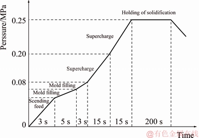
Fig. 1 Process of low-pressure casting to fabricate SiC3D/Al composites
2.2 Fabrication of pad material
The raw materials were graphite particles (��=2.2 g/cm3, d50<200 ��m, from Huasheng Graphite Factory, Heilongjiang Province, China) and ��-SiC powders (��=3.18 g/cm3, purity >99%, d50<0.5 ��m, from Tangshan Hexagon Co., Ltd., Hebei province, China). The volume ratio of SiC to graphite was 2:3. The phenol formaldehyde resin was used as the binding agent. The graphite particle was coated by SiC powder. The powder was pressed at 50 MPa inside a steel die with 42 mm in diameter to form pellets with 12 mm in height to increase the strength of green compact. The green compact was heated at 250 ��C for 24 h, and then sintered at 2050 ��C for 60 min at 30 MPa in graphite moulds at vacuum of about 30 Pa by using the impulsion hot pressing furnace (Jinxing Co., Ltd., Liaoning Province, China). The heating rate was 5 ��C/min.
2.3 Test equipment and procedure
2.3.1 Phase composition
The composites were crushed into powders and analyzed by XRD, via a computer-controlled diffractometer (PANALYTICL B.V/PW3040/60, Netherlands) with Cu K�� radiation at 40 kV and 100 mA. Data were digitally recorded in a continuous scanning mode in an angle (2��) range of 10��-90�� with a scanning rate of 0.02 (��)/s.
2.3.2 Microstructure
The microstructure of the composites was characterized using optical metallography (OM, GX71, Olympus, Japan), and scanning electron microscopy (SEM, SU4800, Shimadzu, Japan). The worn surface was observed after 30 min ultrasonic cleaning to remove most debris attached on the worn surface. The worn surface was observed by confocal laser scanning microscope (CLSM, Axio-Imager LSM-800, Zeiss, Germany). The element composition analysis was conducted by an energy-dispersive X-ray spectrometer (EDS).
2.3.3 Friction and wear properties test
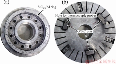
Fig. 2 Macro-morphologies of SiC3D/Al rotating brake ring (a) and G/SiC pins (b) before testing
The rotating brake ring shown in Fig. 2(a) was machined from SiC3D/Al with an outer diameter of 140 mm, an inner diameter of 118 mm, and a thickness of 10 mm. The effective radius of the braking ring was 64.5 mm. The counterparts (pins) shown in Fig. 2(b) were machined from G/SiC with a thickness and a surface area of 8 mm and 2 cm2, respectively. G/SiC pins were fixed on the stationary disc. The hole (indicated by the red arrow) was used to measure the friction surface temperature of the G/SiC pins with a stainless steel sheath (diameter of 0.40 mm) chromel-alumel thermo- couple probe, which was embedded in a hole of 2 mm in diameter, 3-4 mm in depth and beneath 1.0 mm from wear surface of the G/SiC pins. An infrared thermometer was used as well to acquire the temperature data of the SiC3D/Al ring.
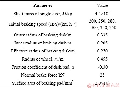
Tests of friction and wear properties of the samples were carried out on the MM3000-type sub-scale testing machine (Xi��an Shuntong Technical Research Institute, Shanxi Province, China) at room temperature and a relative humidity of 45%, and more details about the testing can be found in the literature [22]. Based on a scale-conversion rule [23,24], the braking inertia and the normal brake pressure are set as 1.05 kg��m2 and 1.25 MPa, respectively. The simulation data at the emergency braking conditions of real HSTs are listed in Table 1.
Table 1 Parameters of real HSTs under emergency braking conditions
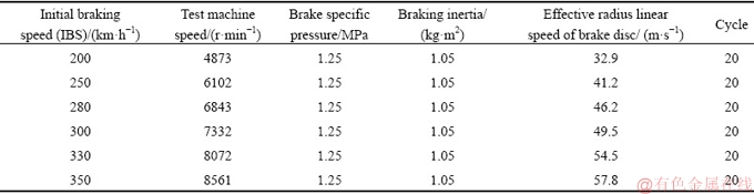
The experimental parameters for sub-scale testing are listed in Table 2. The applied initial rotation speed was 4873-8561 r/min (32.9-57.8 m/s in effective radius linear velocity of brake disc), corresponding to the initial braking speed (IBS) of 200-350 km/h of the HSTs. Before data collection, pins were burnished by a bedding-in process to format in friction layer on the rubbing surfaces and to ensure a consistent braking performance. During the tests, the disc with initial inertia of 1.05 kg��m2 was rotated up to 4873-8561 r/min before each braking, and then the fixed 1.25 MPa was applied on one side of the pin through a gas-operated piston till the flywheel completely stopped. The braking parameters such as stopping distance, temperature, stopping time, COF and torque were recorded by the computer.
Table 2 Experimental parameters for sub-scale testing
A series of 20 repetitive tests were performed [25]. After each set of stops, sufficient time was given to the pins and ring to cool to the room temperature. The specimens were thoroughly cleaned with acetone in an ultrasonic cleaner before and after the wear test, and were weighed before and after each test to measure the wear rate. The mass loss during the wear test was measured using a photoelectric balance with the resolution of ��0.1 mg [26].
Average COF, ��t, is calculated by the computer system based on Eq. (1):
 (1)
(1)
where �� is the transient COF and s is the braking distance.
The stable COF, ��s, during each braking test is calculated as
 (2)
(2)
where ��max is the maximum COF during each braking test.
3 Results and discussion
3.1 Microstructure and phase composition of SiC3D/Al
The macrograph of green SiC bodies with reticulated porosity is shown in Fig. 3(a). The SiC preform before infiltration shown in Fig. 3(b) indicates that the pores are similar hexagonal holes with an average pore diameter of 1.5-2.5 mm. The predominant phases of SiC preforms are SiC and SiO2 indicated by the XRD pattern shown in Fig. 3(c). When SiC preforms are heated at 1200 ��C for 2-4 h in a stationary air ambient, SiC reacts with the oxygen to form a thin layer of SiO2 on the surface of SiC preforms, according to the reactions given by Eq. (3). This method could be effective for prohibiting a direct contact between SiC preforms and the Al alloy matrix to form Al4C3. Thin SiO2 layers formed on the SiC preforms are shown in Fig. 3(d).
2SiC+3O2��2SiO2+2CO (3a)
SiC+2O2��SiO2+CO2 (3b)
The density of SiC3D/Al composite measured by Archimedes method is 2.85 g/cm3. The relative density of SiC3D/Al is more than 99%. Figure 4 shows the microstructures of SiC3D/Al after T6 heat treatment. The molten Al alloy infiltrates the SiC RPCs completely. The microstructure of SiC3D/Al is in agreement with the co-continuous SiC/Al described in Refs. [27,28]. Al alloy matrix in the SiC3D/Al is characterized by the presence of Al dendrites, surrounded by the Si eutectic structure. Intermetallic phases, containing Fe, Mg, Cu and Si, forming during solidification and remaining undissolved by the T6 treatment, are also observed in interdendritic region, as shown in Fig. 4(a). Strengthening intermetallic precipitates induced by T6 treatment, due to their nano size, cannot be detected by OM [29]. In this work, secondary dendrite arm spacing (SDAS) with maximum size of about 20 ��m is obtained by adding Sr as the grain refiner. From the micrograph in Fig. 4(b), thin SiO2 layer may be seen at the interface of the infiltrated SiC strut and Al alloy, and no bulk second phases could be observed in the composites.
SEM and surface scanning analysis of SiC3D/Al are shown in Fig. 5. Figures 5(a, b) illustrate that the interface is clean even after SiC RPCs have been infiltrated by molten Al alloy. The continuous interfacial bonding with a thickness of 1-4 ��m forms at the Al/SiC interface. This indicates that the SiO2 layers protect the inner SiC struts from the attack of molten Al. Figures 5(d, f) indicate that the predominant phases of the layers are SiO2, which agrees well with the XRD pattern of SiC preforms. The intermetallic phases, containing Si, Mg, Fe, Mn and Cu elements, are also found, which agrees with the OM morphology analysis.
3.2 Microstructures and properties of G/SiC
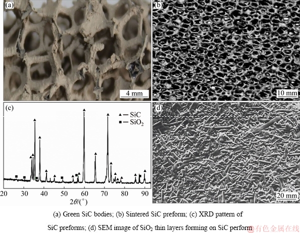
Fig. 3 Microstructures and phase constitutions of SiC preforms
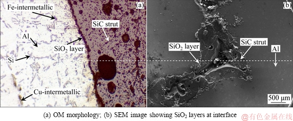
Fig. 4 Microstructures of interface of SiC3D/Al composite after T6 heat treatment
The apparent porosity, bulk density, fracture toughness and flexure strength of G/SiC composite, with a volume ratio of SiC to graphite of 2:3 sintered at 2050 ��C for 60 min at 30 MPa, are measured to be 4.0%, 2.58 g/cm3, 6.3 MPa��m1/2 and 80 MPa, respectively. Graphite particles are observed to be embedded in the SiC matrix, as shown in Fig. 6(a). The linear scan result is shown in Fig. 6(b). The phase analysis indicates that the predominant phases of the composite are graphite and SiC. The silicon atoms diffuse into the graphite phase as well. The SEM images of the fracture morphologies of G/SiC composite are shown in Figs. 6(c, d). The graphite cores are pulled out of the SiC matrix, as shown in Fig. 6(c), and the flaws are formed, as shown in Fig. 6(d). The incorporation of graphite cores into the SiC matrix forms the weak graphite/SiC interfaces. The weak graphite/SiC interfaces can absorb larger amounts of fracture work and improve the crack tolerance greatly, so the fracture toughness increases remarkably.
3.3 Frictional properties of tribo-couple
Figure 7 shows the average COF (��t) and stable COF (��s) of SiC3D/Al against G/SiC at IBS of 200-350 km/h and 1.25 MPa. The ��t decreases from 0.335 to 0.301, and the ��s decreases from 0.78 to 0.42 with an increase of IBS from 200 to 350 km/h.
Figure 8 shows the torque of SiC3D/Al against G/SiC at IBS of 200-350 km/h and 1.25 MPa. The torque exhibits the similar tendency of a ��saddle�� shape, namely a relatively smooth middle stage. The sharp peak appears at the end of the curve. The fluctuation of COF will reduce ��s. The large fluctuation of COF agrees well with the feature of the ��s in Fig. 7.
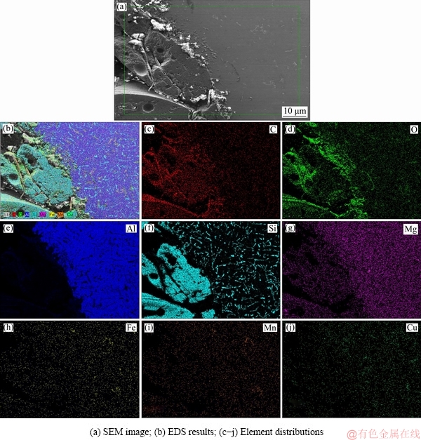
Fig. 5 SEM and EDS surface scanning analysis results of SiC3D/Al
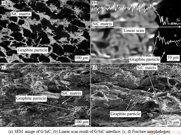
Fig. 6 Microstructures of G/SiC with volume ratio of SiC to graphite of 2:3, sintered at 2050 ��C for 60 min at 30 MPa
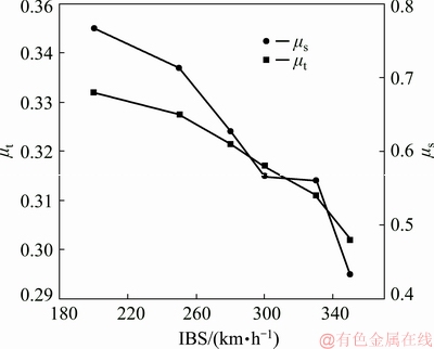
Fig. 7 Relationship between COF and IBS
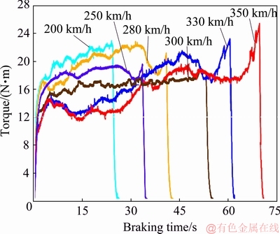
Fig. 8 Torques of SiC3D/Al against G/SiC at IBS of 200-350 km/h and 1.25 MPa
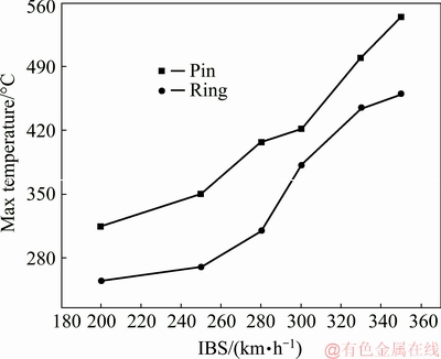
Fig. 9 Max friction surface temperature of SiC3D/Al ring and G/SiC pins at IBS of 200-350 km/h and 1.25 MPa
Figure 9 shows the max temperature of the SiC3D/Al ring and G/SiC pins at different IBSs under 1.25 MPa. The max friction surface temperature of the SiC3D/Al ring increases from 255 to 460 ��C, and the max friction surface temperature of the G/SiC pins increases from 314 to 544 ��C with an increase of IBS from 200 to 350 km/h, respectively. The high temperature or ��flash temperature�� produced by friction may be close to or exceed the melting point of Al alloy (about 600 ��C), resulting in liquid phase in the local area of ring and pin friction surface, and bonding between ring and pin friction surface, namely ��cold welding�� phenomenon. When the brake ends and the ring and pin are needed to be separated, the bonding of the ring and pin results in friction torque sharply increasing at the end of braking, especially in high braking speed conditions.
Figure 10 shows the braking distances of SiC3D/Al against G/SiC at IBS of 200-350 km/h and 1.25 MPa. The braking distances of the SiC3D/Al ring increase from 1980 to 4686 m, with the IBS increasing from 200 to 350 km/h. The test values in this study are lower than the standard values [30].
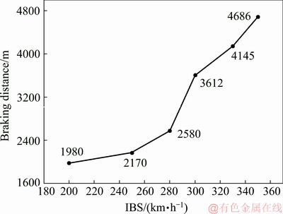
Fig. 10 Braking distances of SiC3D/Al against G/SiC at IBS of 200-350 km/h and 1.25 MPa
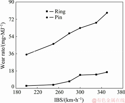
Fig. 11 Wear rates of SiC3D/Al and G/SiC at different IBSs under 1.25 MPa
Figure 11 shows the wear rate of SiC3D/Al against G/SiC at IBS of 200-350 km/h and 1.25 MPa. The wear rate of the SiC3D/Al increases from 0.38 to 14.6 mg/MJ, and the wear rate of the G/SiC increases from 32.1 to 76.4 mg/MJ with the IBS increasing from 200 to 350 km/h. SiC struts effectively support the applied pressure on the sliding surface and restrict the plastic deformation of the Al alloy matrix by the high temperature softening. Even if the friction surface temperature increasing and thermal softening of Al matrix lead to higher wear rates of SiC3D/Al at higher speeds, the test values in this study are lower than those of SiCp/Al composites and steel. The SiC3D/Al greatly improves wear-resistance at higher pressure, and the G/SiC friction materials have been put forward to upgrade the performance of heat fading resistance [31]. This indicates that SiC3D/Al-G/SiC tribo-couples have the longer service life [32].
3.4 Morphologies of SiC3D/Al worn surface
Figure 12 shows the SiC3D/Al rings and G/SiC pins after testing. It is observed that the continuous black lubricating mechanically mixed layer (MML) forms gradually on the worn surfaces during the friction process.
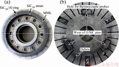
Fig. 12 Macro-morphologies of SiC3D/Al ring (a) and G/SiC pin (b) after testing
The worn surface morphology of the SiC3D/Al at IBS of 200-350 km/h and 1.25 MPa was characterized using optical metallography. The wear grooves show the evidence of severe plastic flow in the form of grooves parallel to the sliding direction (SD, arrow direction inFigs. 13(a-f)). Figure 13(a) depicts the worn surface tested at 200 km/h. Obvious parallel grooves are observed due to the abrasion of the exposed SiC struts. The average micro-cutting wear groove width is 3.5 ��m. There are still many SiC powders retained on the worn surface even after ultrasonic cleaning with acetone. Figure 13(b) depicts the worn surface tested at 250 km/h. Some SiC powders are ploughed out from both the lower and upper counter-faces of the SiC3D/Al and G/SiC during the braking tests, and these powders are embedded into worn surface again. Figure 13(c) depicts the worn surface tested at 280 km/h. The Al alloy is smeared out of the SiC struts, and then elongates along the sliding direction. The wear grooves can still be distinguished. Figure 13(d) depicts the worn surface tested at 300 km/h. The worn surface shows shallow unidirectional grooves. Figure 13(e) depicts the worn surface tested at 330 km/h. The quantity of embedded particles is increased. The spalled pieces are squeezed and rolled on the friction surface, leading to the little ��s. The metal matrix illustrates the adhesive wear with extensive plastic deformation, evidenced by smearing at the edge of the wear track [33]. Figure 13(f) depicts the worn surface tested at 350 km/h. Some SiC struts are exposed in the fracture zones, indicating that the interface of SiC and Al might be a source of the delamination fracture [34].
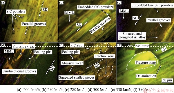
Fig. 13 OM images of worn counter-face morphologies of SiC3D/Al ring at different IBSs under 1.25 MPa
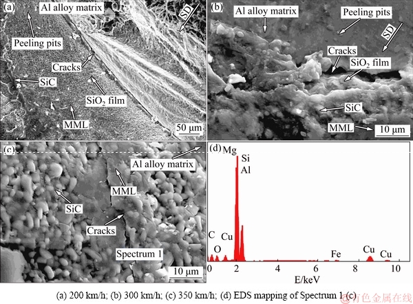
Fig. 14 SEM and EDS result of worn surface of SiC3D/Al at different IBSs under1.25 MPa
The worn surface of the SiC3D/Al at different IBSs under 1.25 MPa was characterized using SEM and EDS. Figure 14 shows magnified images of the worn surface covered with the MML after multiple braking times. It can be found that the SiO2 layers between the SiC struts and the Al alloy matrix are gradually destroyed, as compared to Fig. 4. This MML is dominated by a quite smooth tribo-oxide layer. In addition, a few exposed graphite, SiC particles, Al alloy matrix and small peeling pits are contained [33]. Moreover, many cracks perpendicular to the sliding direction appear on the tribo-oxide film owing to stress from periodic fatigue, as shown in Figs. 14(a) and (b). Graphite in the MML serves to lubricate and maintain stable friction in the period of braking, as shown in Fig. 14(c). MML improves the friction and wear performance of the brake ring at high temperature. EDS mapping of Spectrum 1 in Fig. 14(c) shows that MML contains Al, O, C, Si, Mg, Fe, Mn and Cu elements. It is also indicated that Al-rich oxides are produced on the friction surface. The MML is composed of the ductile Al abrasive particles formed by the shear of Al matrix, SiC fine powder formed by the scratch of SiC struts, as well as small graphite particles formed by the scratch of G/SiC pins. In addition, the composites tested at high IBS exhibit intense fluctuation, which is associated with the intermittent formation and removal of the MML.
Figure 15 shows the detailed CLSM analysis results of the cross-sectional images of the friction layer in SiC3D/Al at different IBSs under 1.25 MPa. In Figs. 15(a) and (c), in MML, it is convex in SiC struts, however, it is concave in Al alloy matrix, showing obvious regular fluctuation. Due to the support of high-strength and high-melting-point SiC struts, the plastic deformation and softening of Al alloy were restricted. SiC struts pin the soft Al alloy matrix at the original position without serious distortion even the Al alloy matrix is torn by force of friction. Additionally, the continuous MML is gradually destroyed, and the delamination becomes more and more remarkable. There exist more micro-holes in the MML coatings under the action of shearing force and heat due to serious wear damage at higher IBS. In Figs. 15(b) and (d), the average thicknesses of MML obtained at 200 and 350 km/h are 15 and 20 ��m, respectively.
3.5 Morphologies of G/SiC worn surface
The worn surface morphologies of G/SiC pins at IBS of 200-350 km/h under 1.25 MPa are shown in Fig. 16. Figure 16(a) depicts the worn surface tested at 200 km/h. The pins are scratched by the SiC protuberances. Figure 16(b) depicts the worn surface tested at 250 km/h. The number of the shallow grooves is reduced in comparison with that in Fig. 16(a). Figure 16(c) depicts the worn surface tested at 300 km/h. The cracks are perpendicular to the siding direction, evident on the worn surfaces of G/SiC, and the density of cracks increases remarkably with an increase of IBS. Deep grooves and a few micro-cracks are clearly observed. Micro-cracks, macro-cracks and dramatic surface damage are predominant features. The size of the wear debris increases with an increase of the IBS, resulting in large wear loss at higher IBS. Figure 16(d) depicts the worn surface tested at 350 km/h. The damage to the MML is aggravated by the counter face, because the abrasive particles and SiC protuberances deeply penetrate into graphite in the pin.
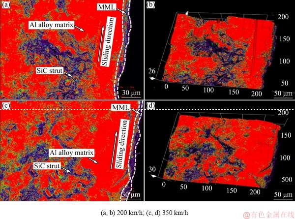
Fig. 15 CLSM analysis results of cross-sectional images of friction layer in SiC3D/Al at different IBSs under 1.25 MPa
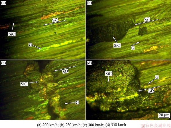
Fig. 16 Worn counter-face morphologies of G/SiC pins at different IBSs under 1.25 MPa
3.6 Composition of debris
Figure 17 shows the composition of debris at different IBS under 1.25 MPa. It is revealed that SiC3D/Al typically exhibits abrasive wear at IBS of 200 km/h in Fig. 17(a), while oxidation wear and delamination are observed when IBS is increased to 350 km/h in Fig. 17(c). The debris is rich in Al, Mg, Si and O by EDS analysis. It is noted that the composition of the debris is similar to that of the MML in Figs. 17(b) and (d), indicating that the debris is essentially peeled from the MML. The finding agrees well with the worn counter-face morphologies of SiC3D/Al ring at different IBS shown in Fig. 13. The gradual increase in the O content from the substrate to the friction surface indicates that oxidation gradually increases with braking time. The friction surface temperature and braking distance determined by the IBS are the main factors to influence braking performance of SiC3D/Al-G/SiC tribo-couples.
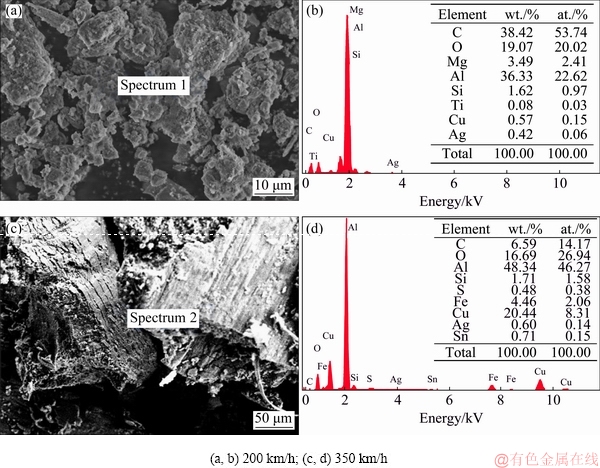
Fig. 17 Compositions of debris at different IBSs under 1.25 MPa
3.7 FE simulation of wear behavior
A simple two-phase geometry was used to represent the SiC3D/Al-G/SiC tribo-couple. Figure 18 shows the generated three-dimensional FE model (2 mm �� 2 mm �� 2 mm) of the SiC3D/Al-G/SiC tribo-couple using Solidwork2016, as well as the SiC struts, Al, graphite particles and SiC. Three-dimensional FE models with mixed tetrahedral/hexahedral meshes are generated using Solidwork2016 simulation. The properties of SiC structure are defined as elastic modulus of 450 GPa, Poisson ratio of 0.10, density of 3.15 g/cm3, ��b of 200 MPa, and shear modulus of 192 MPa. The properties of graphite are defined as elastic modulus of 25 GPa, Poisson ratio of 0.28, density of 2.24 g/cm3 and ��b of 65 MPa. The properties of Al alloy are defined as elastic modulus of 66 GPa, Poisson ratio of 0.32, density of 2.7 g/cm3, ��b of 285 MPa, ��s of 215 MPa, and shear modulus of 195 MPa. The load is applied on the top face of the unit in the z-direction. The xy and yz planes are constrained and the opposite plane is required to displace during deformation by load (z direction) and shear force (x direction), as shown in Fig. 18. The perfect bonding between the two phases is assumed in the model. Al alloy behaves in a perfectly elasto-plastic manner, while SiC and graphite are modeled as isotropic fully-elastic solids.
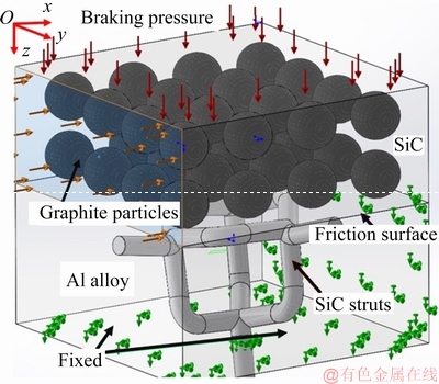
Fig. 18 FE model for SiC3D/Al-G/SiC tribo-couple
The simulation results of wear behavior of SiC3D/Al-G/SiC tribo-couple at different IBSs under 1.25 MPa computed by Solidwork2016 are shown in Fig. 19. It is revealed that IBS is a significant factor in adhesive wear. The thermal expansion (CTE) mismatch between Al alloy matrix and SiC struts during the braking process is repeatedly larger than the critical strength of Al alloy matrix. During the thermal expansion, Al alloy matrix yields upon plastic deformation around micro-voids shown in Figs. 19(c, d). The micro-voids relieve the local constraint and enable plastic deformation to compensate for the thermal strain mismatch between the matrix and reinforcement, thus reducing the CTEs of the composites to a certain extent. The FE calculation data agree well with the wear behavior of SiC3D/Al-G/SiC tribo-couple.
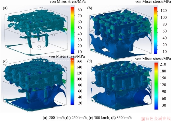
Fig. 19 Simulation results of wear behavior of SiC3D/Al-G/SiC tribo-couple at different IBSs under 1.25 MPa
3.8 Friction and wear mechanisms
It can be known from the finite element calculation that the main wear mechanisms of the SiC3D/Al-G/SiC tribo-couples are oxidation-abrasion, fatigue wear, and adhesive wear. In SiC3D/Al brake ring, oxidation-abrasion, fatigue wear, and adhesive wear always occur simultaneously, and there are mutual enhancing effects among them. For materials such as Al alloys, in which free electrons exist, the conduction of thermal energy occurs through the flow of free electrons. For materials such as SiC in which no free electrons exist, the conduction of thermal energy occurs through the flow of phonons [35]. As a result, the conduction of thermal energy occurs through the flow of free electrons in Al alloy matrix and flow of phonons in SiC struts for SiC3D/Al composite. The interface between SiC struts and Al alloy can scatter the free electrons and phonons during heat conduction. SiC3D/Al composite has less interfacial area between Al and SiC, which will lead to a smaller scattering effect during the flow of free electrons and phonons when being compared with SiCp/Al composite. This results in great improvement of thermal conductivity, which is important to lowering the friction surface temperature. So, the SiC3D/Al-G/SiC tribo- couples exhibit better friction performance than the PMM brake material-iron/steel or SiCp/Al composite tribo-couples.
4 Conclusions
(1) LPCM is adopted to fabricate the SiC3D/Al via Al alloy liquid filling the oxidized SiC RPC preforms, and hot-pressuring sintered (HPS) process is adopted to fabricate G/SiC composite.
(2) MML controls greatly the frictional and wear properties of the tribo-couples. SiC3D/Al and G/SiC tribo-couples feature low temperature, reliable friction factor, and high durability. With an increase of IBS from 200 to 350 km/h, ��t decreases from 0.335 to 0.301, ��s decreases from 0.78 to 0.42, the wear rate of the SiC3D/Al ring increases from 0.38 to 14.6 mg/MJ, the wear rate of the G/SiC increases from 32.1 to 76.4 mg/MJ, the max temperature of the SiC3D/Al ring increases from 255 to 460 ��C, and the max temperature of the G/SiC pins increases from 314 to 544 ��C.
(3) The wear mechanism of SiC3D/Al is typically abrasive wear at IBS of 200-300 km/h, with the local area characterized by oxidation-abrasion, fatigue wear, and adhesive wear. With the increase of IBS to 350 km/h, the oxidation wear and delamination are the main wear patterns. The wear behavior of the tribo-couple predicted using the Solidwork2016 simulation agrees well with the experimental results.
References
[1] ZHANG P, ZHANG L, FU K X, WU P F, CAO J W, SHIJIA C R, QU X H. Fade behaviour of copper-based brake pad during cyclic emergency braking at high speed and overload condition [J]. Wear, 2019, 428-429: 10-23.
[2] WANG D M, ZHENG Z X, LV J, XU G Q, ZHOU S A, TANG W M, WU Y C. Enhanced thermal conductive 3D-SiC/Al-Si-Mg interpenetrating composites fabricated by pressureless infiltration [J]. Ceramics International, 2017, 43(2): 1755-1761.
[3] PENG T, YAN Q Z, LI G, ZHANG X L, WEN Z F, JIN X S. The braking behaviors of Cu-based metallic brake pad for high-speed train under different initial braking speed [J]. Tribology Letters, 2017, 65(4): 135-148.
[4] YU L, JIANG Y L, LU S K, RU H Q, FANG M. FEM for brake discs of SiC 3D continuous ceramic reinforced 7075 aluminum alloy for CRH3 trains applying emergency braking [J]. Applied Mechanics and Materials, 2012, 120: 51-55.
[5] ZHU J B, YAN H. Fabrication of an A356/fly-ash-mullite interpenetrating composite and its wear properties [J]. Ceramics International, 2017, 43(15): 12996-13003.
[6] WANG B, ZHAO S, OJIMA F, YANG J F, ISHIZAKI K. Pulse electric current sintering of 3D interpenetrating SiC/Al composites [J]. Ceramics International, 2017, 43(2): 2867-2870.
[7] PAN L K, HAN J M, YANG Z Y, WANG J L, LI X, LI Z Q, LI W J. Temperature effects on the friction and wear behaviors of SiCp/A356 composite against semimetallic materials [J]. Advances in Materials Science and Engineering, 2017, 2017: 1-12.
[8] NONG X D, JIANG Y L, FANG M, YU L, LIU C Y. Numerical analysis of novel SiC3D/Al alloy co-continuous composites ventilated brake disc [J]. International Journal of Heat and Mass Transfer, 2017, 108: 1374-1382.
[9] JIN Z H, TOHGO K, FUJII T, SHIMAMURA Y. Double edge thermal crack problem for an interpenetrating phase composite: Application of a matricity-based thermal conductivity model [J]. Engineering Fracture Mechanics, 2017, 177: 167-179.
[10] DOLATA A J. Tribological properties of AlSi12-Al2O3 interpenetrating composite layers in comparison with unreinforced matrix alloy [J]. Materials, 2017, 10(9): 1045-1059.
[11] LIU J, BINNER J, HIGGINSON R. Dry sliding wear behaviour of co-continuous ceramic foam/aluminium alloy interpenetrating composites produced by pressureless infiltration [J]. Wear, 2012, 276: 94-104.
[12] CREE D, PUGH M. Dry wear and friction properties of an A356/SiC foam interpenetrating phase composite [J]. Wear, 2011, 272(1): 88-96.
[13] AHMED F, SRIVASTAVA S, AGARWAL A B. Synthesis & characterization of Al-Ti-Cr MMC as friction material for disc brakes application [J]. Materials Today-Proceedings, 2017, 4(2): 405-414.
[14] BARROS L Y, NEIS P D, FERREIRA N F, PAVLAK R P, MASOTTI D, MATOZO L T, SUKUMARAN J, DEBAETS P, ANDO M. Morphological analysis of pad-disc system during braking operations [J]. Wear, 2016, 352-353: 112-121.
[15] BIAN G Y, WU H Z. Friction surface structure of a Cf/C-SiC composite brake disc after bedding testing on a full-scale dynamometer [J]. Tribology International, 2016, 99: 85-95.
[16] UMANATH K, PALANIKUMAR K, SELVAMANI S T. Analysis of dry sliding wear behaviour of Al6061/SiC/Al2O3 hybrid metal matrix composites [J]. Composites Part B: Engineering, 2013, 53: 159-168.
[17] RAM PRABHU T, VARMA V K, VEDANTAM S. Effect of SiC volume fraction and size on dry sliding wear of Fe/SiC/graphite hybrid composites for high sliding speed applications [J]. Wear, 2014, 309(1-2): 1-10.
[18] WANG L L, FAN Q B, LI G J, ZHANG H M, WANG F C. Experimental observation and numerical simulation of SiC3D/Al interpenetrating phase composite material subjected to a three-point bending load [J]. Computational Materials Science, 2014, 95: 408-413.
[19] JIANG Lan, JIANG Yan-li, YU Liang, SU Nan, DING You-dong. Experimental study and numerical analysis on dry friction and wear performance of co-continuous SiC/Fe-40Cr against SiC/2618 Al alloy composites [J]. Transactions of Nonferrous Metals Society of China, 2012, 22(12): 2913-2924.
[20] JIANG Lan, JIANG Yan-li, YU Liang, SU Nan, DING You-dong. Thermal analysis for brake disks of SiC/6061 Al alloy co-continuous composite for CRH3 during emergency braking considering airflow cooling [J]. Transactions of Nonferrous Metals Society of China, 2012, 22(11): 2783-2791.
[21] VOIGT C, ZIENER T, SCHUBERT P, ANEZIRIS C G, HUBALKOVA J. Reticulated porous foam ceramics with different surface chemistries [J]. Journal of the American Ceramic Society, 2014, 97(7): 2046-2053.
[22] SANDERS P G, DALKA T M, BASCH R H. A reduced-scale brake dynamometer for friction characterization [J]. Tribology International, 2001, 34(9): 609-615.
[23] ALNAQI A A, BARTON D C, BROOKS P C. Reduced scale thermal characterization of automotive disc brake [J]. Applied Thermal Engineering, 2015, 75: 658-668.
[24] KUMAR M, BIJWE J. NAO friction materials with various metal powders: Tribological evaluation on full-scale inertia dynamometer [J]. Wear, 2010, 269(11-12): 826-837.
[25] SHARIFI H, OSTOVAN K, TAYEBI M, RAJAEE A. Dry sliding wear behavior of open-cell Al-Mg/Al2O3 and Al-Mg/SiC-Al2O3 composite preforms produced by a pressureless infiltration technique [J]. Tribology International, 2017, 116: 244-255.
[26] ABARGHOUIE S M R M, REIHANI S M S. Investigation of friction and wear behaviors of 2024 Al and 2024 Al/SiCp composite at elevated temperatures [J]. Journal of Alloys and Compounds, 2010, 501(2): 326-332.
[27] RAMESH R, PRASANTH A S, RAGAVAN M, LIKHITH M. SiC/aluminium co-continuous composite synthesized by reactive metal penetration [J]. Applied Mechanics and Materials, 2014, 592-594: 847-853.
[28] ZHAO M J, LI N, ZHAO L Z, ZHANG X L. Numerical simulation on mechanical properties of SiC/Al co-continuous composites [J]. Advanced Materials Research, 2011, 213: 186-190.
[29] ZHAO L Z, ZHAO M J, LI Na, ZHANG X L, YAN H. Investigation on compression behavior of SiC/Al co-continuous composites [J]. Materials Science Forum, 2011, 689: 130-133.
[30] YU L, YANG K P, NONG X D, JIANG Y L, GE N N, FANG M. Finite element simulation and experimental analysis on fatigue behavior of SiCn/Al Co-continuous composites [C]// BERNARD D, BUFFIERE J Y, POLLOCK T, POULSEN H F, ROLLETT A, UCHIC M. Proceedings of the 2nd International Congress on 3D Materials Science, Cham: Springer International Publishing, 2016: 67-72.
[31] GIL R, JINNAPAT A, KENNEDY A R. Pressure-assisted infiltration of molten aluminium into open cell ceramic foams: Experimental observations and infiltration modeling [J]. Composites Part A: Applied Science and Manufacturing, 2012, 43(6): 880-884.
[32] VAUCHER S, KUEBLER J, BEFFORT O, BIASETTO L, ZORDAN F, COLOMBO P. Ceramic foam-reinforced Al-based micro- composites [J]. Composites Science and Technology, 2008, 68(15-16): 3202-3207.
[33] KAUSHIK N C, RAO R N. Influence of applied load on abrasive wear depth of hybrid Gr/SiC/Al-Mg-Si composites in a two-body condition [J]. Journal of Tribology, 2017, 139(6): 061601.
[34] FAN S W, ZHANG L T, CHENG L F, ZHANG J X, YANG S J, LIU H Y. Wear mechanisms of the C/SiC brake materials [J]. Tribology International, 2011, 44(1): 25-28.
[35] LI S, XIONG D G, LIU M, BAI S X, ZHAO X. Thermophysical properties of SiC/Al composites with three dimensional interpenetrating network structure [J]. Ceramics International, 2014, 40(5): 7539-7544.
�����г�SiC3D/Al�ƶ���-ʯī/SiCĦ��ƬĦ�������Ʊ������ṹ��Ħ��ĥ������
�� ��1,2��������3���� ��3�������1,2��������1,2�����Ѷ�1,2�����߷�1,2
1. ������ѧ �������������̬��ұ��������ص�ʵ���ң����� 110819��
2. ������ѧ ұ��ѧԺ������ 110819��
3. ����������ѧ ��ɫ���������ϼӹ��¼����������ص�ʵ���ң����� 541004
ժ Ҫ�����������ƶ�������о�ʯī/SiC(G/SiC)���ϲ����뻥���ิ�ϲ���(IPC) SiC3D/Al��Ħ��ĥ�����ܡ�����������ת��ԭ��ȷ�������г��ƶ������������������ƶ�ѹ��Ϊ1.25 MPa����ʼ�ƶ��ٶ�(IBS)Ϊ 200~350 km/h������ɨ��羵(SEM)��X����������(XRD)��������(EDS)��Ħ��ż���Ͻ��б��������������ƥ���Ħ��������Ħ�������¶ȵ͡�Ħ�������ȶ����;��Գ����ص㡣Ħ������ĥ�������Ħ�����������γ� �����Ļ�е��ϲ�(MML)����е��ϲ��ɶ���������ɣ�����ؿ��Ƹ��ϲ��ϵ�ĥ���ʺ�Ħ������(COF)������ʼ�ƶ��ٶ�Ϊ200~300 km/hʱ��SiC3D/Al��ĥ�����Ϊ���͵�ĥ��ĥ�𣻵���ʼ�ƶ��ٶ����ӵ�350 km/hʱ���ɹ۲쵽����ĥ��Ͱ���ֲ���������Solidwork Simulation������Ħ������ĥ����Ϊ����Ԥ�⣬����������ʵ�������ǺϽϺá�Ħ��������������г������ƶ���Ҫ��
�ؼ��ʣ�SiC3D/Al��ʯī/SiC��Ħ������ĥ������֯�������ƶ�����
(Edited by Bing YANG)
Foundation item: Project(51465014) supported by the National Natural Science Foundation of China; Project (1099043) supported by Scientific and Technological Research Program of Guangxi, China; Projects (2014GXNSFAA118351, 2014GXNSFAA118329, 2012GXNSFBA053156) supported by the Natural Science Foundation of Guangxi, China
Corresponding author: Liang YU; Tel: +86-13591633992; E-mail: 2010054@glut.edu.cn
DOI: 10.1016/S1003-6326(19)65097-1
Abstract: The friction and wear properties of interpenetrating phase composites (IPC) SiC3D/Al sliding against graphite/SiC (G/SiC) composites were investigated using a sub-scale brake dynamometer. The testing conditions included a braking pressure of 1.25 MPa and an initial braking speed (IBS) of 200-350 km/h in a braking process of high-speed train according to the scale-conversion rules. The tribo-couple materials were characterized using scanning electron microscopy (SEM), X-ray diffractometry (XRD), and energy-dispersive X-ray spectrometry (EDS). It is found that the matching tribo-couple features low friction surface temperature, reliable friction factor, and high durability. The continuous lubricating mechanically-mixed layer (MML) forms gradually on the worn surfaces of ring in the friction process. The MML is heterogeneous, which greatly controls wear rate and coefficient of friction (COF) of the composites. The wear mechanism of SiC3D/Al is typically abrasive wear at an IBS of 200-300 km/h. When the IBS increases to 350 km/h, oxidation wear and delamination are observed. The friction behavior of the tribo-couple predicted using Solidwork simulation software agrees well with the experimental results. The tribo-couple meets the requirement of emergency braking of high-speed train.
