

Development of single-action, two-step clinching system using finite element analysis
Seong-Wook LEE1, Tae-Hyung KIM2, Geun-Jo HAN3
1. Power & Industrial Systems R&D Center, Hyosung Corporation, Changwon, 641-712, Korea;
2. Department of Mechanical Engineering, K. I. T., Busan, 617-701, Korea;
3. Department of Mechanical Engineering, Dong-A University, Busan, 604-714, Korea
Received 2 March 2009; accepted 30 May 2009
Abstract:
Traditional manufacturing processes for bending and combining the upper and lower heat insulation plates for a car catalytic converter need two kinds of bending dies. This study was carried out to develop a single-action, two-step clinching system for clinching heat insulation plates. To design the operating mechanism for this clinching system, finite element analysis was used to estimate the bending load needed and to predict the bent shape of the heat insulation plate. Then a recovery and cushioning system was designed for the bending die. It is expected that this new process will improve the manufacturing quality of heat insulation plates and will reduce manufacturing cost. And a higher value-added technique for mold and pressing systems was introduced.
Key words:
catalytic converter; heat insulation plate; clinching process; FEA;
1 Introduction
Catalytic converters are important air pollution control components of car exhaust systems. A converter essentially consists of upper and lower heat insulation plates combined by a flange that encloses the catalyst and a heat insulating material around the catalyst. This heat insulating material lowers the temperature of the exhaust pipe to prevent misfire of the catalytic converter and protects the catalytic converter from damage by shocks from road or ground surfaces[1-2]. The heat insulating plates are joined by a sheet metal method known as clinching.
Clinching has been used for almost 25 years and there has been much research into this method[3-7]. The traditional clinching technique used to combine the upper and lower heat insulation plates of a catalytic converter has two steps: first, the flanges of the cases of the upper and lower heat insulation plates are combined by the clinching process, and second, the combination is finalized in a press. Therefore, two molds are needed for one joining process. Moreover, because the product must be moved between the first clinching and the press, the procedure requires significant manpower, equipment, and space.
In this study, we designed system that allows a single-action clinching of the heat insulation plates of a car catalytic converter. Our aim was to develop a single-action, two-step clinching system that could combine and bend the upper and lower heat insulation plates for the catalytic converter with one set of molds and one stroke. The operating mechanism was designed for the total system, and finite element analysis was used to predict the bending load needed for clinching and the shape after bending[8]. As a final enhancement, we also designed cushions to improve the bending of the heat insulation plates and to increase the clinching force.
2 Mechanism of single-action, two-step clinching system
2.1 First stage
As shown in Fig.1, in the first stage, the upper and lower cases of the heat insulation plates of the catalytic converter are attached to the mold. A predefined hydraulic pressure is then applied to each cushion from a hydraulic pump. Hydraulic pressure is supplied to the main cylinder that lowers the top mold, and the preparation for the clinching process is completed.
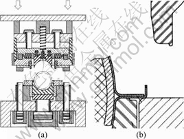
Fig.1 First stage of clinching mechanism: (a) Clinching die; (b) Clinching part
2.2 Second stage
As shown in Fig.2(a), once the main cylinder is activated and the top mold is lowered, the top plate, combined with the top mold, drops down, together with a punch casing.
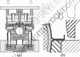
Fig.2 Second stage of clinching mechanism: (a) Clinching die; (b) Clinching part
Consequently, as shown in Fig.2(b), the punch falls onto the top surface of the bending mold, and is now ready for the clinching process.
2.3 Third stage
As shown in Fig.3(a), the fall of the punch casing is stopped by the first cushion located at the left and right sides of the bottom mold, but the top mold keeps falling because of the continuous hydraulic pressure applied to it.
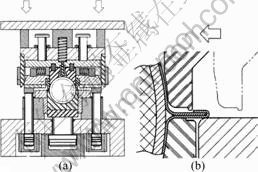
Fig.3 Third stage of clinching mechanism: (a) Clinching die; (b) Clinching part
As a result, wedging pushes the horizontal movement block inside, and the first clinching process is completed as shown in Fig.3(b).
2.4 Fourth stage
Even after the first clinching process is completed, hydraulic pressure continues to be applied to the top mold and it keeps falling.
The punch that has moved inside now bends the upper and lower cases vertically, as shown in Fig.4(b).
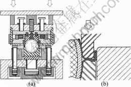
Fig.4 Fourth stage of clinching mechanism: (a) Clinching die; (b) Clinching part
Finally, the second cushion drops down to perform embossing, to increase the combining force after bending, and this completes the entire clinching process.
3 Determination of clinching load
3.1 Finite element model
This study used finite element analysis to determine the bending load required for the first and second steps of the clinching process. Finite element analysis has been widely used for the prediction of forming shapes and the estimation of bending load in the bending and clinching process[9-13]. Fig.5 illustrates the finite element model used for analysis.
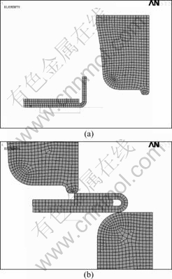
Fig.5 Finite element models of clinching part according to clinching process: (a) First clinching process; (b) Second clinching process
The upper and lower heat insulation plates are excluded from the analysis model because they are fixed by the top and bottom jigs of the molds. Therefore, the flange of each case that is bent by clinching, the punch and the bending mold are modeled and included in the finite element analysis. Because the longitudinal dimensions of the upper and lower heat insulation plates are sufficiently greater than the sectional thickness, the plane strain conditions for the finite element analysis are assumed in order to shorten convergence and analysis time[14-15].
Table 1 lists the mechanical properties of the materials used for the heat insulation plates.
Table 1 Properties of heat insulation plate materials

3.2 Load and boundary conditions
To calculate the first clinching load, as shown in Fig.5(a), the punch is forced to move from right to left while the left end of the heat insulation plate flange is held fixed, thus causing the heat insulation plate to bend.
To calculate the second clinching load, as shown in Fig.5(b), the punch is dropped while the left end of the first clinched heat insulation plate case flange is kept fixed, thus bending the heat insulation plate.
3.3 First clinching load
Fig.6(a) shows the mechanism of the first clinching process, and Fig.6(b) shows the deformed shape of the heat insulation plate after the clinching process, as obtained from finite element analysis.

Fig.6 Equivalent stress distribution of heat insulation plate after first clinching process: (a) Clinching part; (b) Equivalent stress distribution (unit: MPa)
Fig.7 shows the result of finite element analysis for the reaction generated from the fixed end of the heat insulation plate flange against the clinching movement of the punch. The reaction changed because of the variation in the plastic deformation of the heat insulation plate flange by the movement of the punch. The total load generated in the first clinching process is 554 N/mm, integrating all reactions.
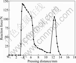
Fig.7 First clinching force variation according to pressing distance of punch
3.4 Second clinching load
Fig.8(a) shows the mechanism of the second clinching process, and Fig.8(b) shows the deformed shape of the heat insulation plate after the clinching process, as obtained from finite element analysis.
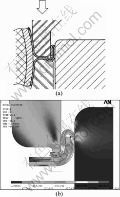
Fig.8 Equivalent stress distribution of heat insulation plate after second clinching process: (a) Clinching part; (b) Equivalent stress distribution (unit: MPa)
Fig.9 shows the result of finite element analysis for the reaction generated from the fixed end of the heat insulation plate case flange by the dropping of the punch. The total load generated in the second clinching process is 493 N/mm, integrating all reactions.
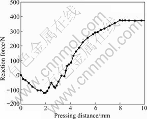
Fig.9 Second clinching force variation according to pressing distance of punch
4 Cushion design
The single-action, two-step clinching system that is the subject of this study, uses two cushions[16-17]. The first cushion supports the top mold and enables the first clinching, while the second cushion is used for embossing, to improve the combining force of the upper and lower heat insulation plates after the first and second clinching processes. Therefore, each cushion needs to be controlled. The hydraulic system shown in Fig.10 is designed to appropriately control these cushions for the bending process.
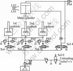
Fig.10 Hydraulic circuit diagram for cushions
Fig.11 shows a control flowchart for the hydraulic system presented in Fig.10. First, a predefined hydraulic pressure to withstand the clinching load, obtained from finite element analysis, is supplied from the hydraulic tank to each cushion. Then a solenoid valve blocks the hydraulic pressure to the cushions and the solenoid valve 4B opens to apply hydraulic pressure to the main cylinder that activates the top mold. When this hydraulic pressure pushes down the top mold, one stroke performs two clinching processes for the upper and lower heat insulation plates of the catalytic converter, by the mechanism explained in section 2.
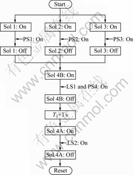
Fig.11 Control flow chart of hydraulic circuit
Then, when the second cushion drops, the hydraulic pressure applied to the main cylinder is stopped by closing the solenoid valve 4B. After one second, for embossing, hydraulic pressure to raise the main cylinder is applied to it by opening the solenoid valve 4A, returning the top mold to its original position.
Finally, when the top mold returns, the solenoid valve 4A is closed by a limit switch and the system process is complete.
5 Conclusions
This study designed an operating mechanism for a total system to provide a single-action clinching of the heat insulation plates of car catalytic converters, an operation that traditionally requires two processing actions. The new system also introduces cushions to improve clinching efficiency and combining force, and analyzes the clinching loads with finite element analysis.
The single-action, two-step clinching system described here enables the first and second clinching processes for the upper and lower heat insulation plates of the catalytic converter, with only one set of molds and one stroke. The development of this system could save manpower, equipment, space and logistics cost, and improve quality by simplifying the manufacturing process for heat insulation plates of catalytic converters.
Furthermore, because this clinching system can be applied to related pressing techniques using other molds, it should create high added value for many molding and pressing techniques.
Acknowledgements
This study was supported by research funds from Dong-A University.
References
[1] CROUSE W H, ANGLIN D L. Automotive mechanics [M]. 10th ed. USA: McGraw-Hill, 2001: 131.
[2] LEE S R, LIM B O, HA J R, KIM W B. Automotive engineering [M]. Korea: Bosunggak, 2000: 346.
[3] VARIS J P. The suitability of round clinching tools for high strength structural steel [J]. Thin-Walled Struc, 2002, 40(3): 225-238.
[4] VARIS J P. The suitability of clinching as a joining method for high-strength structural steel [J]. J Mater Proc Technol, 2003, 132(1/3): 242-249.
[5] VARIS J P, LEPISTO J. A simple testing-based procedure and simulation of the clinching process using finite element analysis for establishing clinching parameters [J]. Thin-Walled Struc, 2003, 41(8): 691-709.
[6] PAULA A A, AGUILAR M T P, PERTENCE A E M, CETLIN P R. Finite element simulations of the clinch joining of metallic sheets [J]. J Mater Proc Technol, 2007, 182(1/3): 352-357.
[7] NEUGEBAUER R, KRAUS C, DIETRICH S. Advances in mechanical joining of magnesium [J]. CIRP Annals-Manu Technol, 2008, 57(1): 283-286.
[8] CHOI D O. The press for the manufacturing catalytic converter of automobile(patent id:10-0541235-0000) [P]. Korea, 2005.
[9] KAZAN R, FIRAT M, TIRYAKI A E. Prediction of springback in wipe-bending process of sheet metal using neural network [J]. Materials & Design, 2009, 30(2): 418-423.
[10] SUN Z, YANG H. FEM analysis of effect of die angle on tube inversion forming process under conical die [J]. J Mater Sci Technol, 2003, 19(1): 234-236.
[11] HAMA T, NAGATA T, TEODOSIU C, MAKINOUCHI A, TAKUDA H. Finite-element simulation of springback in sheet metal forming using local interpolation for tool surfaces [J]. Int J Mech Sci, 2008, 50(2): 175-192.
[12] POIZAT C, SCHMITT W, KRASOWSKY A, ANDRIEUX F, HAAS E, MOLL R. Evaluation and improvement of the bending process of connector elements by finite element simulations [J]. J Mater Sci Technol, 2004, 20(1): 49-51.
[13] LI G, KANG Y. FEM simulation of bending formability for laminate steel/resin/steel lightweight composite sheet [J]. J Mater Sci Technol, 2003, 19(4): 324-326.
[14] ZIENKIEWICZ O C, TAYLOR R L. The finite element method [M]. 5th ed. UK: Butterworth-Heinemann, 2000: 87.
[15] ANSYS Inc. ANSYS user��s manual (v11) [M]. USA, 2007.
[16] JOHNSON J L. Introduction to fluid power [M]. USA: Thomson Learning, 2002.
[17] SEO E S, LEE J S. Hydraulic control system [M]. Korea: Bomundang, 2000.
Corresponding author: Geun-Jo HAN; Tel: +82-51-200-7650; Fax: +82-51-200-7656; E-mail: lsw1126@naver.com
(Edited by HE Xue-feng)
[1] CROUSE W H, ANGLIN D L. Automotive mechanics [M]. 10th ed. USA: McGraw-Hill, 2001: 131.
[2] LEE S R, LIM B O, HA J R, KIM W B. Automotive engineering [M]. Korea: Bosunggak, 2000: 346.
[15] ANSYS Inc. ANSYS user��s manual (v11) [M]. USA, 2007.
[16] JOHNSON J L. Introduction to fluid power [M]. USA: Thomson Learning, 2002.
[17] SEO E S, LEE J S. Hydraulic control system [M]. Korea: Bomundang, 2000.
