

Surface treatment of 3D outside serrated integral-fin tube
manufactured by rolling and extrusion
BAI Peng-fei(������), LIU Xiao-kang(����), YAN Hui(�� ��), TANG Biao(�� ��)
School of Mechanical and Automotive Engineering, South China University of Technology,
Guangzhou 510640, China
Received 12 May 2009; accepted 3 September 2009
Abstract:
The outside serrated integral-fin tubes fabricated by rolling-plowing-extrusion processing were surface-treated through different processes of annealing in hydrogen atmosphere, electrochemical corrosion or sandblasting. The purpose was to eliminate residual stress, clear secondary micro-fins and enhance heat transfer performance. By comparing the surface characteristics, it is found that the finned tubes treated by electrochemical corrosion have the most glabrous surfaces where the fins are almost perfectly reserved. Clear layer cracks can be observed on the top of the fins. These structures are effective in enhancing heat transfer performance when being applied to flow heat exchange. Therefore, the finned tubes treated by electrochemical corrosion are proper for the tubular exchanger with water coolant. The finned tubes treated by sandblasting have rougher surfaces with layer cracks and micro gaps removed. As these structures are useful to clearing adhesive feculence, the tubes are more suitable for the tubular heat exchanger with oil coolant.
Key words:
finned tube; surface treating; heat transfer; multi-dimensional surface;
1 Introduction
The increasing price of energy sources and raw materials greatly promotes the development of efficient heat exchange components in recent years. Especially, surface heat function structure (SHFS) has been an important research subject. Micro-fin structure has prominent performance on enhancing the flow boiling among numerous kinds of surface heat function structures while the increase of flow resistance is relatively limited[1]. So, it is quickly developed and has become a prevalent approach in improving the efficiency of the heat exchanger[2-3]. As the third-generation heat exchange components[4-5], three-dimensional finned tubes can increase the heat transfer area by 2-10 times and yield a heat transfer enhancement of 50%-180%[6-9], compared with the smooth tubes of similar inner diameter under the same operation conditions. In addition, increasing nucleating cavities on heat exchange surface is an excellent way to enhance heat transfer. SCOTT and MASSOUD[10] attained three-dimensional porous SHFS in hill-piled shape by using the copper powder sintering technology. It is experimentally shown it can enhance the critical heat flux of the pool-boiling by nearly three times compared with plain surface. GRIFFITH and WALLIS[11] theoretically discussed the role of nucleating cavities on the rough heat transfer surface to enhance boiling. Surface structures have important influence on the heat transfer of exchangers. In the present research, the outside serrated integral-fin tubes were fabricated by means of rolling-plough-extrusion processing. The finned tubes have an integrated structure which can eliminate the contact thermal resistance between the tube and fins in comparison with the conventional composite finned tubes. The cracked irregularly-shaped submicroscopic structure on the top of fins not only brings about high surface roughness but also forms an excellent nucleating boiling structure.
2 Rolling-plough-extrusion processing
The experiment was carried out on the lathe C6132A1. The oxygen-free copper tubes with a diameter of 12.6 mm and a thickness of 1.25 mm were used as based tubes, and the material of tool was W18Cr4V. The parameters of blade are as follows: ��=8? and ��=14? (�� is the rake angle of blade and �� is the primary forming angle). According to the experiment, the forming process of 3D integral-fin by rolling-plough-extrusion processing methods included two steps: the rolling and the plough-extrusion (P-E)[12].
During the rolling, the outside surface of copper tube was under the press force of the rolling tool. Spiral grooves were formed by the wedge blade which pressed the surface of copper tube to make it plastically deformed, as shown in Fig.1. The height of the rolling tool was expressed as h, the diameter as Dt, and the thickness as w. Then, the following relations must be met:
![]() (1)
(1)
where Db is the root diameter; n is the number of tooth; and �� is the top angle of tooth. During the rolling process, a closely contacted stick should be inserted in the copper tube to prevent the appearance of concave wall. A movable support was installed in order to avoid the copper tube bending in the processing.
In the second step, the approximate finned structure of cubic diamond was formed by P-E processing, as shown in Fig.2, which can be disassembled into two actions: hump formation and hump plough. The extrusion face of blade made the plastic flow of the metal

Fig.1 Schematic diagram of rolling processing: (a) Rolling processing using rolling tool; (b) Surface structure after rolling processing

Fig.2 Schematic diagram of P-E processing
on extrusion face side appear. The accumulation and the formation of hump took place under the function of the rotating movement of the work-piece and the feed movement of the tool. The copper tube was driven by the rotating basic shaft to get the rotary motion; meanwhile, the rolling tool was compelled to revolve synchronously. As tool feeding, the hump was spitted by the top blade of the tool. The extrusion formation and the hump plough were carried out simultaneously.
When the hump and spiral grooves were ploughed by the top blade of the tool, the formed face of the tool extruded the right side of the metal. This caused the plastic deformation to the former irregular shape followed by the extrusion shape and trajectory of the tool. At last, fins regularly formed under the function of the friction between the extruding face of the tool and the metal[13].
When the parameters of tools were changed, different kinds of finned structures could be shaped[14]. Large cracks were generated at the top of the fins under the function of the deformation of the finned tube. The friction between the tool and the tube body led to the secondary micro-fins formed in the P-E processing, as shown in Fig.2. Though the roots of the secondary micro-fins had been broken, parts of them were still closely connected with the finned tube. These secondary micro-fins could not be effectively removed by traditional cleaning, while they would fall when they were applied to the shell and tube heat exchanger under the concussion and erosion of high-speed oil flow and thermal stress. It would not only result in the pollution to the circulating cooling oil, but also cause fatal harm to the circulation pump. Therefore, the outside finned tube surface should be treated in order to eliminate the above problems and maintain or even enhance the heat transfer performance of finned tubes.
3 Surface treatment
The surface of outside serrated integral-fin tubes fabricated by means of rolling-plowing-extrusion processing was treated by annealing in hydrogen atmosphere, electrochemical corrosion or sandblasting. The purpose of surface treatment is to eliminate secondary micro-fins which were not firmly connected with main fins and fracture debris, while the fins structure was maintained basically.
3.1 Hydrogen annealing process
In annealing process of the finned tubes in the furnace with hydrogen atmosphere, the layer cracks on the top of the tubes were fused, and residual stress was also eliminated. The heating temperature was up to 950 ��. Nitrogen was used as the protection gas when the temperature was below 500 ��. Hydrogen was used as the reductive gas when the temperature was higher than 500 ��.
From SEM images of outside surface of finned tube before and after hydrogen annealing in Fig.3, the annealing process obviously improved the surface finish of the finned tubes, effectively fused the micro-cracks, highlighted cavities on the fin surface, and at the same time, to the full extend maintained the surface characteristics of the original tube. However, the processing could not remove secondary micro-fins completely. Some secondary micro-fins that were easy to be fractured were still attached to the fin surface. But, these secondary micro-fins could be removed by ultrasonic washing and high-speed water flow cleaning,
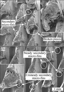
Fig.3 SEM image of outside surface of finned tube: (a) Original; (b) After hydrogen annealing
because the hardness of copper greatly decreased after the annealing processing. Yet, small burrs could not be removed by hydrogen annealing.
3.2 Electrochemical corrosion process
The electrochemical corrosion process used in this research was similar to the electrochemical polishing used commonly except a greater current and a longer working time. Experiments showed that the electrochemical corrosion process could effectively dissolve away the surface burrs of finned tubes, and remove the secondary micro-fins and fractured debris. In this process, the stainless steel was used as the cathode, and the original finned tube as the anode. The power was a 12 V battery with the maximum current up to 60 A. Battery power can provide more stable current output than the rectifier used commonly. The output current of battery had almost no ripple, which effectively prevented the electric arc generated within the sample and the dirt deposits on the cathode.
The electrolyte was mainly composed of the mixture of H3PO4 and CrO3 and the electrolysis time was 4 min. The specific process parameters are listed in Table 1 and the SEM image of the finned tube is shown in Fig.4. Electrochemical corrosion process was a very effective way to remove secondary micro-fins. The fins had an improved surface finish and a smooth micro-surface without burrs. But the top of the fins was so seriously eroded that the fins height decreased. The layered cracks dissolved out from the peak of the fins after being corroded. These layered cracks could greatly
Table 1 Parameters of electrochemical corrosion process

Fig.4 SEM image of fins after electrochemical corrosion
enhance the flow heat exchange performance. During the electrochemical corrosion process, the charge inclined to concentrate at the surface of the protruding metal, and therefore resulted in a good performance on removing fracture debris. However, the corrosion on the base of the fins was weak, which to a large extent maintained the original status.
3.3 Sandblasting process
In the sandblasting process, the size of the quartz sand particles was 50-120 ��m, the spray time was 1 min, and the blasting angle between the spray direction and finned tubes was 45?-60?. As shown in Fig.5, the sandblasting process was most effective for deburring and removing fractured micro-fins on the finned tube. Micro-pits were left at the surface of the fins, and surface roughness of the finned tube was increased, which resulted in the improvement in the heat transfer performance of the heat exchanger. Under the high-speed collision of the sand, layer cracks disappeared and the top of the fin converted to mushroom-like shape. This also resulted in the decrease of the total surface area compared with the original fin. The surface defects decreased after sandblasting, which further improved the corrosion resistance of finned tube.

Fig.5 SEM image of fins after sandblasting
3.4 Comparison of structure on heat transfer enhancement
The structural optimization of the heat transfer surface is an efficient way to improve heat transfer characteristics of the heat exchanger. Fig.6 shows the finned tube samples processed by three types of surface treatment. The large specific surface of the finned tube greatly increased the contact area between the heat transfer surface and the fluid. Staggered fins could disturb the heat boundary layer of the fluid on the surface of the tube, which made the fluid participation in heat transfer achieve the turbulence status at a lower Re number. And it was the very effective way to improve the heat transfer performance by transiting the fluid flow

Fig.6 Appearances of fins after different surface processes: (a) Hydrogen annealing; (b) Electrochemical corrosion; (c) Sandblasting
from laminar to turbulent. When the fluid boiled, the surface microspores on the finned tube became the active points where the liquid bubbles could be generated easily, and it effectively dropped the boiling superheat.
By comparing the finned tubes obtained by three kinds of processes, hydrogen annealing was found to have the least effect on the original fins. The fins maintained an integrated structure; the secondary micro-fins were kept substantially, and the finned tube had a smooth surface. Secondary micro-fins were mostly dissolved after electrochemical corrosion process, and the surface of the fins chapped many layer cracks which worked as the active points during the process of boiling heat exchange. Due to the polishing effect of the electrochemical corrosion, the finned tube after this process had an extremely glossy appearance. However, the reduction of surface roughness was slightly unfavorable to the heat exchange performance. Morphology of the fins on the finned tube changed after the sandblasting process. Under the impact of the quartz sand, the surface work-hardening happened in the fins, and both the micro-fins and the layer cracks disappeared. The top of the fins became smooth, but the height of the fins was lowered and the total specific surface also declined, which resulted in the weakened performance of breaking flow boundary layer. However, with the appearance of micro-pits under the impact of the quartz sand, the surface roughness was improved. Experimental results showed that the rough surface had about 10% increase in the critical heat load of the boiling flow[15].
Generally, the finned tubes processed by electrochemical corrosion are fit for the heat exchanger when water is used as coolant. This process not only is very effective on removing the secondary micro-fins but also makes layer cracks precipitate clearly. This process of electrochemical corrosion would also increase the corrosion resistance of the fins by improving the surface finish.
4 Conclusions
1) The 3D integral outside finned tubes fabricated by means of rolling-plowing-extrusion processing has an excellent heat transfer performance when being applied to tubular heat exchanger after the surface processing.
2) By treating the fins with three types of surface process, it is found that the finned tubes treated by electrochemical corrosion have glabrous surfaces. The fins are almost preserved perfectly. The clear layer cracks emerged from the top of the fins and are effective in enhancing heat transfer performance when being applied to boiling heat transfer. Accordingly, the finned tubes treated by electrochemical corrosion are fit for the tubular heat exchanger by using water as coolant.
3) The finned tubes treated by sandblasting have rougher surface while layer cracks and micro gaps are removed. Consequently, these structures are helpful for clearing adhesive feculence and more suitable for the tubular heat exchanger by using oil as coolant.
References
[1] ZHANG Z G, XU T, FANG X M. Experimental study on heat transfer enhancement of a helically baffled heat exchanger combined with three-dimensional finned tubes [J]. Applied Thermal Engineering, 2004, 24: 2293-2300.
[2] MIYARA A, OTSUBO Y. Condensation heat transfer of herringbone micro fin tubes [J]. International Journal of Thermal Sciences, 2002, 41(7): 639-645.
[3] OCTAVIO L, GILBERT D M, ERIK D. Study of the optimal layout of cooling fins in forced convection cooling [J]. Microelectronics Reliability, 2002, 42(7): 1101-1111.
[4] BERGLES A E. Enhanced heat transfer: Endless frontier, or mature and routine? [J]. Journal of Enhanced Heat Transfer, 1999, 6(2/4): 79-88.
[5] BERGLES A E. Advanced enhancement-third generation heat transfer technology or the ��Final Fronier�� [J]. Transaction of the Institute of Chemistry Engineering, Part A, 2001, 79: 437-444.
[6] BRIGGS A, ROSE J W. An evaluation of models for condensation heat transfer on low-finned tubes [J]. Journal of Enhanced Heat Transfer, 1999, 6(1): 51-60.
[7] MURASE T, WANG H S, ROSE J W. Effect of inundation for condensation of steam on smooth and enhanced condenser tubes [J]. International Journal of Heat and Mass Transfer, 2006, 49: 3180-3189.
[8] CAVALLINI A, DEL COL D, DORETTI L, LONGO G A, ROSSETTO L. Heat transfer and pressure drop during condensation of refrigerants inside horizontal enhanced tubes [J]. International Journal of Refrigeration, 2000, 23: 4-25.
[9] CHENG W Y, WANG C C, HU Y Z. Film condensation of HCFC-22 on horizontal enhanced tubes [J]. International Communications in Heat Transfer, 1996, 118: 79-90.
[10] SCOTT G L, MASSOUD K. Pool-boiling CHF enhancement by modulated porous-layer coating: Theory and experiment [J]. International Journal of Heat and Mass Transfer, 2001, 44: 4287-4311.
[11] GRIFFITH P, WALLIS J D. The role of surface condition in nucleate boiling [J]. Chen Eng Progr Symp Ser, 1960, 56(30): 49-63.
[12] XIANG Jian-hua, TANG Yong, YE Bang-yan, ZHOU Wei, YAN Hui, HU Zhi-hua. Compound forming technology of outside 3D integral fin of copper tubes [J]. Trans Nonferrous Met Soc China, 2009, 19: 335-340.
[13] TANG Yong, XIA Wei, LIU Shu-dao, ZENG Zhi-xin, YE Bang-yan. Fin formation model during pre-roll plough of copper 3D outside fin tube [J]. Trans Nonferrous Met Soc China, 2001, 11(5): 712-716.
[14] CHEN Pin, TANG Yong, LIU Xiao-kang, LIU Xiao-qing. Formation of intergral fins function-surface by extrusion-plough process [J]. Trans Nonferrous Met Soc China, 2006, 16: 1029-1034.
[15] WU Bin, XIA Wei, TANG Yong. Developmen t of new type 3D In tegral-fin copper tubes [J]. Chinese Mechanical Engineering, 2002, 13(13): 1134-1136.
(Edited by YANG Bing)
Foundation item: Projects(50675070, 50930005) supported by the National Natural Science Foundation of China; Project(U0834002) supported by the Natural Science Foundation of Guangdong Province, China
Corresponding author: BAI Peng-fei; Tel/Fax: +86-20-87114634; E-mail: deer_phil@yahoo.com.cn
DOI: 10.1016/S1003-6326(09)60224-7
