
J. Cent. South Univ. (2013) 20: 501�C509
DOI: 10.1007/s11771-013-1512-0

Influences of pre-existing fracture on ground deformation induced by normal faulting in mixed ground conditions
CAI Qi-peng(������)1, NG C W W(���ΰ)2 , LUO Guan-yong(�����)3, HU Ping(��ƽ)4
1. College of Civil Engineering, Huaqiao University, Xiamen 361021, China;
2. Department of Civil and Environmental Engineering,
Hong Kong University of Science and Technology, Hong Kong, China;
3. Department of Civil Engineering, South China University of Technology, Guangzhou 510640, China;
4. Earthquake Administration of Beijing Municipality, Beijing 100080, China
 Central South University Press and Springer-Verlag Berlin Heidelberg 2013
Abstract:
Physical model tests have been conducted by various researchers to investigate fault rupture propagation and ground deformation induced by bedrock faulting. However, the effects of pre-existing fracture on ground deformation are not fully understood. In this work, six centrifuge tests are reported to investigate the influence of pre-existing fracture on ground deformation induced by normal faulting in sand, clay and nine-layered soil with interbedded sand and clay layers. Shear box tests were conducted to develop a filter paper technique, which was adopted in soil model preparation to simulate the effects of pre-existing fracture in centrifuge tests. Centrifuge test results show that ground deformation mechanism in clay, sand and nine-layered soil strata is classified as a stationary zone, a shearing zone and a rigid body zone. Inclination of the strain localization is governed by the dilatancy of soil material. Moreover, the pre-existing fracture provides a preferential path for ground deformation and results in a scarp at the ground surface in sand. On the contrary, fault ruptures are observed at the ground surface in clay and nine-layered soil strata.
Key words:
centrifuge modeling; pre-existing fracture; ground deformation; normal faulting; earthquake��
1 Introduction
Physical model tests have been conducted by researchers to investigate fault rupture propagation induced by bedrock fault movement [1�C5]. These test results showed that when the magnitude of bedrock fault movement is large enough, shear localization might propagate up through soil and result in scarps at ground surface.
Except for scarps, surface fault rupture may also induced by bedrock fault movement [6�C9]. Field case studies formed a basis for current understandings of surface fault rupture [7, 10]. Physical model tests were also conducted by researchers to provided some valuable insight into surface fault rupture [11�C12]. It is found that in addition to the main rupture, extension zones or tension zones might develop at ground surface above the up thrown block in single homogeneous soil stratum. However, the mechanisms for development of surface fault ruptures in nine-layered soil strata are not fully understood.
Bray et al [10] once stated that any existing plane of weakness might affect ground deformation induced by bedrock fault movement. In spite of this awareness, the effects of a pre-existing fracture in soil on ground deformation needs further studies. Lade et al [13] conducted sandbox tests to investigate the influence of the already developed failure surfaces on subsequent propagation of new failure surfaces. In those tests, normal fault movement was first simulated to generate failure surface in the soil model. After that, the bedrock displacement was reversed to study the effects of the already developed failure surface. Finally, they came to a conclusion that the latter failure surfaces developed with shapes and locations were almost unaffected by the initial fault movements. In these tests, it is successful to simulate the reversal of initial bedrock fault movement. With this method, however, the already developed failure surfaces can not be well defined prior to the second bedrock movement.
Hu et al [14] have studied normal fault rupture propagation in three-layered, five-layered and nine-layered soil in the presence of a pre-existing fracture. In these centrifuge tests, a filter paper technique by embedding a filter paper in soil model was adopted to simulate the effects of pre-existing fracture. According to the field studies conducted by Bonilla and Lienkaemper [7], pre-existing fractures in the soil ground are not necessary to pass through the whole soil ground. This finding suggests that the tip of a pre-existing fracture might be located at a certain depth of soil ground.
To enhance the understanding of fault propagation in soil, observations are summarized based on an experimental program developed to study whether and how a pre-existing fracture will influence ground deformation induced by normal faulting in clay, sand and nine-layered soil with interbedded sand and clay layers.
2 Material properties
2.1 Soil type
Two types of soil samples used in the present work were obtained from the Changping area, in the north of Beijing, China. The firstly obtained soil is classified as clay of low plasticity (CL) according to Unified Soil Classification System. The grain size distribution of this clay is 14% sand, 73% silt and 13% clay, with a uniformity coefficient (Cu) of 29. The median particle size d50 is 32 ��m. Atterbeg limits of the clay are: 31 liquid limit (wL) and 22 plastic limit (wP), which yields a plasticity index (PI) of 9. The secondly obtained soil is classified as SPu: uniform, gravelly sand. This sand consists of 98% coarse material (79% sand size and 19% gravel size) and 2% fine material. Median particle size d50 of this sand is 0.74 mm.
2.2 Laboratory test program
To identify soil properties and to develop a technique for simulation of pre-existing fracture in centrifuge, four series of shear box tests were carried out in the laboratory. The first series and the second series of shear box tests were carried out on clay without and with a sandwiched filter paper, respectively. Comparisons between the first and the second series of shear box tests were conducted to study the effects of inclusion of a filter paper on sandwiched clay sample. The third series and the fourth series of shear box tests were carried out on sand without and with a sandwiched filter paper, respectively. These two series of shear box tests aimed at studying the effects of inclusion of a filter paper on sandwiched sand sample.
2.3 Specimen preparation
To prepare soil specimen, both clay and sand were firstly air-dried. Clay lumps were broken down by a mixer and then sieved through a sieve with a size of 2 mm. Water was then added and mixed thoroughly with the sieved clay to a targeted moisture content of 20%. For sand, the targeted water content is 5.5%. Thereafter, well-mixed wet soil samples were kept inside an impervious container for at least 24 h for moisture equalization.
The moist tamping method was selected to produce homogeneous clay and sand specimens. Each test specimen, 70 mm in diameter and 24 mm in height, was compacted in three layers in shear box with a dry unit weight of 16 kN/m3. For tests on a sandwiched soil specimen with a filter paper, each test specimen was compacted by two layers. During model compaction, a filter paper with the same cross-sectional area as that of soil sample was sandwiched between the top and bottom halves of test specimen. Figure 1 shows a sandwiched filter paper in shear box test.
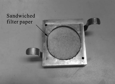
Fig. 1 Sandwiched filter paper in shear box test
2.4 Material behavior in shear box test
Figure 2(a) shows the shear box test results on clay and sandwiched clay with a filter paper. Each shear box test was tested with a vertical stress ranging from 200 kPa to 400 kPa. In shear box tests, shear stress ratio is defined as the ratio of the shear stress to the vertical stress applied to the soil sample [15]. For both clay and sandwiched clay specimens, strain-hardening behavior was observed during shearing. This is consistent with the measured contractive volumetric response shown in Fig. 2(b). The ultimate state, at which the stress ratio approached a constant value, was reached at a shear displacement of about 7 mm. It seems that inclusion of a filter paper has insignificant effect on the behavior of sandwiched clay specimen.
Figure 2(c) shows the strain-softening behavior of sand at normal stress investigated. For sandwiched sand with a filter paper, the filter paper has insignificant effect on the initial stiffness of sand before reaching the peak stage. However, the peak stress ratio is found to be reduced by the sandwiched filter paper. The prevention
of the interlocked fabric of sand particle by the filter paper is expected to be responsible for the reduction in peak strength. Regarding volumetric behavior of sand, a dilative behavior as shearing is observed (see Fig. 2(d)). As expected, the lower the applied vertical stress, the larger the soil dilated. For sandwiched sand, rate of dilation during shearing is found to be suppressed. This is consistent with the measured reduction in peak stress ratio (see Fig. 2(c)). It is therefore feasible to use filter paper to simulate a pre-existing fracture in centrifuge test.
3 Centrifuge modeling of normal faulting
3.1 Experimental program
Six centrifuge tests on modeling ground deformation induced by normal faulting were performed in the 400g-ton, 8.5 m in diameter, geotechnical beam centrifuge in the Hong Kong University of Science and Technology [16]. Each test was carried out under an effective centrifugal acceleration of 100g. The scaling between the model and the prototype is 1/N in the linear dimension.
In Series-1, centrifuge tests CnR, SnR and 9LnR were conducted on clay, sand and nine-layered soil with interbedded sand and clay layers, respectively, without considering the influence of a pre-existing fracture. In Series-2, tests CuR, SuR and 9LuR were conducted with considering a pre-existing fracture on clay, sand and nine-layered soil strata, respectively. The pre-existing fracture starts from the bedrock fault and tilts at an angle of 70o with respect to the horizontal direction (see Fig. 3). It is also assumed that the fracture extents to a depth of Dt below the ground surface. The basic parameters for each centrifuge experiment are summarized in Table 1.
3.2 Experimental set-up and instrumentation
Figure 4 shows a cross-section of experimental apparatus utilized in this work. It is an aluminum plane-strain container fitted with a 100 mm thick Perspex window, which allows observation of soil deformation during testing. The internal dimension of this experimental apparatus is 350 mm �� 1244 mm �� 851 mm (width �� length �� height).
A bedrock fault system consisting of a bedrock foot wall and a bedrock hanging wall is installed at the bottom of the experimental apparatus. The bedrock hanging wall is simulated by a hanging wall block (item 1 in Fig. 4), a roller bearing system (item 2 in Fig. 4) and a hydraulic system (item 3 in Fig. 4). The hanging wall block rests upon the roller bearings, supported by the hydraulic actuator. The bedrock foot wall is simulated by a foot wall block (item 9 in Fig. 4) and kept stationary during test. The height of this block is 231 mm to permit enough space for bedrock fault movement.
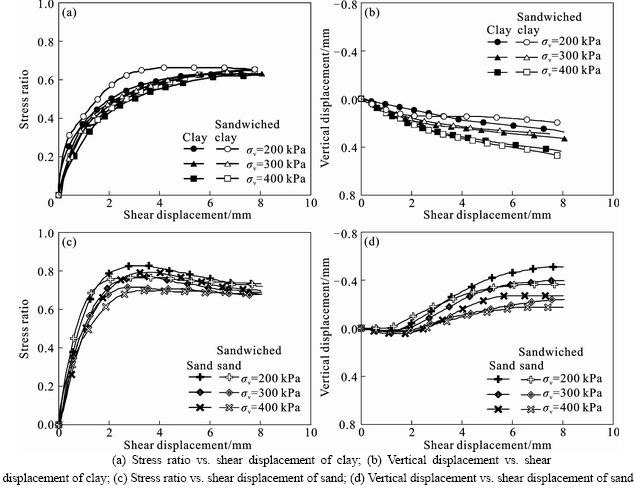
Fig. 2 Material behavior in shear box test:
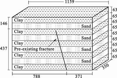
Fig. 3 Schematic diagram of nine-layered soil with a pre- existing fracture (Unit: mm)
Prior to model preparation, oil was transferred into the hydraulic cylinder to elevate the hanging wall base to the height of the foot wall block. The high pressure oil in the hydraulic cylinder maintains weight of overlying soil under both normal gravity and elevated gravity. During centrifuge test, an oil valve (item 6 in Fig. 4) was remotely controlled by a computer and was switched to release the oil in the hydraulic cylinder. The metal platen (item 3a in Fig. 4) then displaces vertically with the aid of four platen guides (item 3d in Fig. 4) around the cylinder. With the aid of the guidance system (item 13 in Fig. 4), foot wall block (item 9 in Fig. 4), roller bearings (item 2 in Fig. 4), and the hanging wall block are displaced at the desired dip angle (70��with respective to the horizontal direction). The spacing between metal platen and cylinder (item 3c in Fig. 4) could be adjusted by the base block (item 4 in Fig. 4) to simulate different magnitudes of bedrock fault movement. Based on research by Wells and Coppersmith [9], maximum surface displacement induced by bedrock fault movement ranges from less than 1 cm to about 10 m. Spacing for vertical bedrock displacement of 0.55 m and 4.20 m in prototype are then chosen in this work.
The vertical soil retaining wall (item 11 in Fig. 4) is fixed in the horizontal direction and free in vertical direction. It displaces consistently with the hanging wall block in vertical direction during modeling of normal faulting to provide a rigid boundary condition for the soil model. This rigid boundary condition represents an extreme case that horizontal displacements are restricted for the soil overlying above the bedrock hanging wall [17].
Four Canon G5 digital cameras, with a resolution of 2592��1944 pixels, were mounted 300 mm in front of the Perspex window. The dashed box shown in Fig. 4 illustrates the viewing areas of 740 mm��550 mm of the four digital cameras. The mean image scale is around 150 ��m/pixel. This value was estimated from the distance between two control markers in opposite corners of the image and used for image calibration based on the assumption of a constant image scale [18]. The ground deformation was subsequently deduced using particle image velocimetry (PIV) coupled with close-range photogrammetric correction [19]. Additional post processing allows calculation of shear strains on the deforming soil.
3.3 Model preparation
Each centrifuge model is constructed by the moist tamping method, the same as that adopted in laboratory tests. The soil model was compacted in 27 layers to a dry unit weight of 16 kN/m3. The targeted moisture contents for clay model and sand model are 20% and 5.5%, respectively. To characterize the excessive densification of the underlying layers during compaction of the succeeding layers, the soil deformation during compaction was captured by digital cameras. The digital images were then analyzed using particle image velocimetry (PIV) to obtain the change in density of the underlying soil layers. The maximum difference in dry densities found in a compacted soil model is generally less than 1%.
For the soil model with pre-existing fracture in Series-2, the soil model overlying above bedrock foot wall was firstly built with the aid of templates. The slope surface designed for the location of the pre-existing fracture was exposed to be covered by a filter paper. Afterwards, the soil model overlying above bedrock hanging wall was prepared to the height of the pre-existing fracture. Finally, the rest of the soil model was compacted until the desired model height was reached.
3.4 Centrifuge test procedure
Each model was accelerated to 100g, which was kept constant for the subsequent consolidation. In each soil model, vertical settlements substantially ceased after 2�C4 h (i.e., 2�C5 a in prototype) of consolidation. The consistent consolidation behavior for the soil models gives us the confidence in the repeatability of the model preparation procedures adopted. After consolidation, normal faulting was simulated in each test by displacing the hanging wall block downward, at a rate of about 0.1 m/s in model scale (i.e., 0.1 m/s in prototype). After each test, post experimental observations and examinations were carried out.
Table 1 Basic parameters of six centrifuge experiments
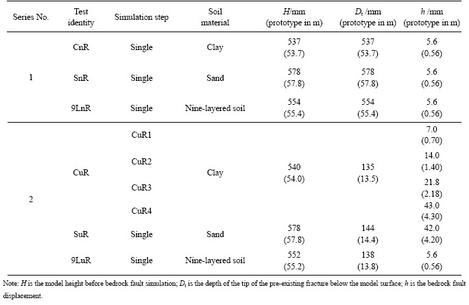
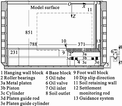
Fig. 4 Cross-section of experimental apparatus installed in plane strain container for centrifuge test (Unit: mm)
4 Results of centrifuge tests
The experimental results are analyzed to differentiate ground deformation induced by normal faulting in three different soil strata. Data presented here are converted into prototypes, unless stated otherwise. The coordinate system adopted for presenting test results is shown in Fig. 4. The soil model heights after consolidation for each test are summarized in Table 1.
4.1 Deformation mechanism in soils without a pre-existing fracture
Figure 5(a) shows the measured soil displacement vectors using the PIV technique in clay (CnR), superimposed by two contour lines of Ds/Db (the magnitude of soil displacement normalized by the magnitude of bedrock fault movement). Displacements were mostly concentrated in the soil overlying the bedrock hanging wall. According to the magnitude of soil displacements, deformed clay was divided into three regions. A stationary zone, where soil remains stationary, was located between the bedrock foot wall and the contour line of Ds/Db=0.1. Within the zone bounded between the contour lines of Ds/Db=0.1 and Ds/Db=0.9, changing magnitudes of the soil displacements indicate that the soil within this zone is likely subjected to shearing. A rigid body zone, where the soil displaces with almost the same direction and magnitude, is bounded by the contour line of Ds/Db=0.9 and the bedrock hanging wall.
Figure 5(b) shows deduced shear strains based on the measured deformation in clay. The deduced shear strain contours confirm that the ground deformation mechanism in clay is classified as a stationary zone, a shearing zone and a rigid body zone. Negligible shear strain was observed within the stationary zone and within the rigid body zone. The shear strain localization tends to develop vertically at deep depth (Z>25 m) and tends to incline to the foot wall side at shallow depth (Z<25 m). Vertical propagation of the strain localization at deep depth is likely to be due to the contractive behavior of clay during shearing, as illustrated in shear box tests on clay in Fig. 2(a). Inclination of the shear strain localization to the foot wall side at shallow depth is expected to be due to the horizontal components of displacement for soil at shallow depth within the shearing zone, as shown in Fig. 5(a).
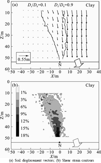
Fig. 5 Ground deformation in clay induced by normal faulting for test CnR:
Figures 6(a) and (b) show the shear strain measured in sand (SnR) and nine-layered soil strata (9LnR), respectively. These two figures are superimposed by two contour lines of Ds/Db=0.1 and Ds/Db=0.9. Consistent with what observed in centrifuge test of CnR, ground deformation mechanism in sand and nine-layered soil strata is classified as a stationary zone, a shearing zone and a rigid body zone. The shearing zone is mainly bounded between two contour lines of Ds/Db=0.1 and Ds/Db=0.9.
Figure 6(a) also shows that the shear strain localization in sand tends to bend over the hanging wall at the soil/bedrock interface. The inclination of the strain localization to the horizontal is about 75o. This inclined shear strain localization is consistent with the observations in centrifuge test results on sand, as reported by Stone and Wood [2]. Inclination of the strain localization is believed to be governed by the dilatancy of soil material.
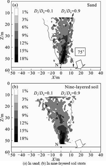
Fig. 6 Shear strain contours of soil induced by normal faulting:
As shown in Fig. 6(b), inclination of shear strain localization in nine-layered soil strata is similar with what observed in clay (see test results of CnR in Fig. 5(b)). The shear strain localization also tends to propagate upward at deep depth (Z>30 m) and tends to incline to the foot wall side at shallow depth (Z<30 m). This suggests that ground deformation in nine-layered soil strata is mainly governed by the clay layers.
4.2 Deformation mechanism in sand with a pre-existing fracture
Figure 7(a) shows ground deformation measured in sand with a pre-existing fracture (SuR), superimposed by two contour lines of Ds/Db. Even though the vertical displacement of the bedrock hanging wall in this test is increased to 4.2 m, the ground deformation mechanism is also classified into a stationary zone, a shearing zone and a rigid body zone. This shearing deformation mechanism is consistent with what observed in test on sand without a pre-existing fracture (as shown in Fig. 6(a)). However, the contour line Ds/Db=0.1 seems to coincide with the pre-existing fracture in test of SuR. The differences of displacement vectors for the soil across the pre-existing fracture are noted. It is evident that it is feasible to simulate the presence of a pre-existing fracture in sand using a filter paper. This also suggests that the pre-existing fracture provides a preferential path for ground deformation. In addition, the dash-dotted line in Fig. 7(a) shows the settlement measured at the model surface during the post experimental observation. It is clearly shown that a scarp at the ground surface above the bedrock foot wall was induced in sand with the presence of a pre-existing fracture.
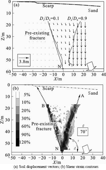
Fig. 7 Ground deformation in sand with pre-existing fracture induced by normal faulting for test SuR:
Figure 7(b) shows the deduced shear strain contours in test of SuR. Two shear strain localizations were observed. For the strain localization NA with larger shear strain, it bent over the hanging wall at the soil/bedrock interface. The location of strain localization NA was similar to that of strain localization observed in test SnR (as shown in Fig. 6(a)). From the surface differential settlement measured during the post experimental observation, it seems that the strain localization NA died out when it approached the surface. No localized differential settlement was observed at the ground surface above the strain localization NA. In contrast, the strain localization NB seems to propagate upwards toward the surface and form a scarp at the ground surface above the bedrock foot wall (located at X=�C25 m). This finding is consistent with the statement by Bray et al [10] that any existing plane of weakness might be suspected when evaluating the potential for ground movement at a project site.
4.3 Development of ground deformation with bedrock faulting
Figures 8(a)�Cd) show the development of ground deformation with four steps of normal faulting in test of CuR. In each step, no significant relative displacement was observed for the soil acrossing the pre-existing fracture. This is likely due to the fact that inclusion of a filter paper has insignificant effect on the behavior of clay, as suggested in shear box tests on sandwiched clay specimen (shown in Fig. 2(a)). It is also found that in each step, the ground deformation mechanism can be classified as a stationary zone, a shearing zone and a rigid body zone. Even though the extent of the shearing zone seems to slightly increase with the development of normal faulting, the shearing ground deformation mechanism remains the same. In addition, the dash-dotted line in Fig. 8(d) shows the settlement measured at the model surface during the post experimental observation. Different from the surface settlement observed in sand (test SuR as shown in Fig. 7(a), no obvious scarp was observed at the ground surface. It seems that clay accommodates significant bedrock faulting by warping without localized deformation.
4.4 Surface fault ruptures induced by normal faulting
Figure 9(a) shows fault ruptures observed at the ground surface in clay (tests CnR). All three surface fault ruptures were observed. The main fault rupture was mainly located around the intersection line of bedrock fault plane and the ground surface (dashed line 11). These ruptures may be generated by horizontal tension stresses on the soil, due to the increase in horizontal soil displacement within the shearing zone (as shown in Fig. 5(a)). Tension cracks at the ground surface induced by normal faulting were also observed in physical tests [11�C12] and in field studies [10]. For tests on clay with a pre-existing fracture (CuR), and three surface fault ruptures were observed (see Fig. 9(b)). Comparisons between Fig. 9(a) and Fig. 9(b) show that the influence zone of surface fault ruptures (measured along the center line of the model) reduced from 21.7 m to 10.6 m with the effects of a pre-existing fracture. The pre-existing fracture tends to reduce the influence zone of fault ruptures at ground surface.
Similar to that observed in clay, four surface fault ruptures were observed in nine-layered soil strata (9LnR) and the main rupture was mainly located around the intersection line of bedrock fault plane and the ground surface (referring to Fig. 9(c)). These observed surface fault ruptures confirm again that ground deformation in nine-layered soil strata is governed by clay layers.
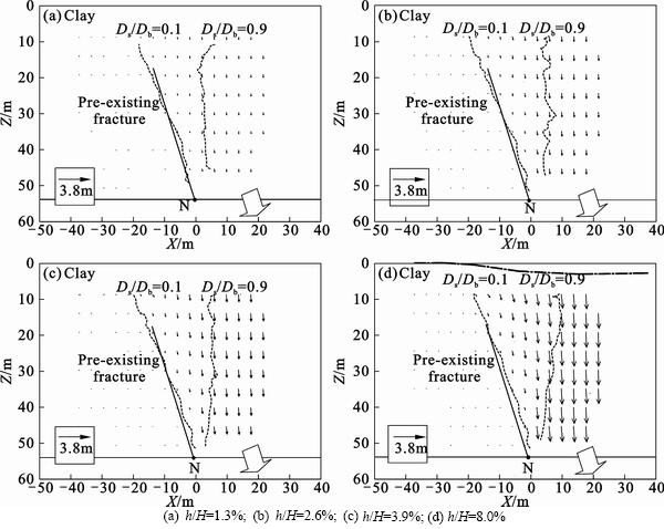
Fig. 8 Development of ground deformation in clay with pre-existing fracture for test CuR4:
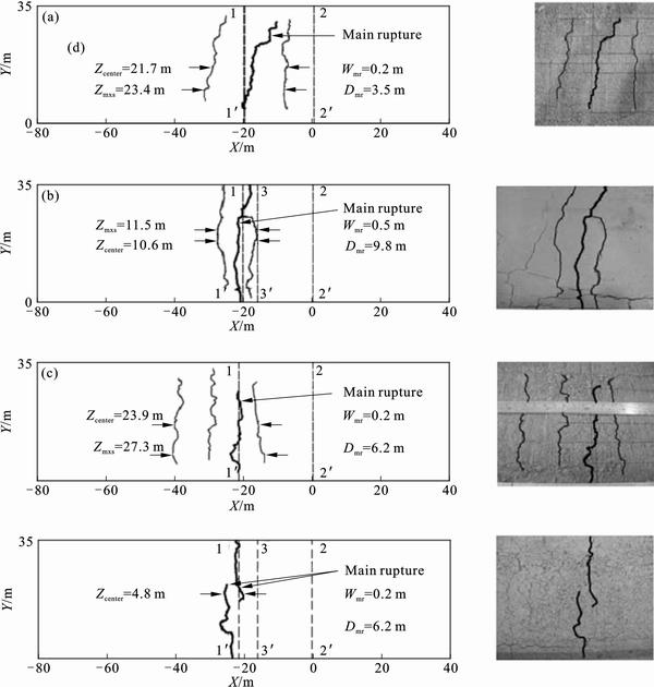
Fig. 9 Surface fault ruptures observed in clay (a), clay with a pre-existing fracture (b); nine-layered soil strata (c); and nine-layered soil strata with a pre-existing fracture (d)
Regarding the nine-layered soil with a pre-existing fracture, only two surface fault ruptures were observed (see Fig. 9(d)). The influence zone of surface fault ruptures reduced from 23.9 m to 4.8 m under the effects of the pre-existing fracture.
5 Conclusions
1) Centrifuge test results show that ground deformation mechanism in clay, sand and nine-layered soil with interbedded sand and clay layers is classified into a stationary zone, a shearing zone and a rigid body zone. In clay and nine-layered soil strata, shear strain localization tends to develop vertically at deep depth and tends to incline to the foot wall side at shallow depth. Ground deformation in nine-layered soil strata is mainly governed by the clay layers. In contrast, shear strain localization in sand tends to bend over the hanging wall at the soil/bedrock interface. Inclination of the strain localization is governed by the dilatancy of soil material.
2) Centrifuge test results on sand with a pre- existing fracture show that the pre-existing fracture provides a preferential path for ground deformation and results in strain localization along the pre-existing fracture. This strain localization seems to propagate upwards and form a scarp at the ground surface above the bedrock foot wall.
3) On the contrary, fault ruptures are observed at the ground surface for the tests on clay and nine-layered soil strata. Discrepancy in horizontal components of soil displacements generates horizontal tension stress at the soil surface and results in the surface fault ruptures. It is found that the pre-existing fracture reduces the influence zone of surface fault ruptures in clay and nine-layered soil strata.
References
[1] COLE D A J, LADE P V. Influence zones in alluvium over dip-slip faults [J]. Journal of Geotechnical Engineering, 1984, 110(5): 599�C615.
[2] STONE K J L, WOOD D M. Effects of dilatancy and particle size observed in model tests on sand [J]. Soils and Foundations, 1992, 32(4): 43�C57.
[3] LEE J W, HAMADA M. An experimental study on earthquake fault rupture propagation through a sandy soil deposit [J]. Structural Engineering/Earthquake Engineering, 2005, 22(1): 1�C13.
[4] ANASTASOPOULOS I, GAZETAS G, BRANSBY M F, DAVIES M C R, EL NAHAS A. Fault rupture propagation through sand: Finite-element analysis and validation through centrifuge experiments [J]. Journal of Geotechnical and Geoenvironmental Engineering, 2007, 133(8): 943�C958.
[5] AHMED W, BRANSBY M F. Interaction of shallow foundations with reverse faults [J]. Journal of Geotechnical and Geoenvironmental Engineering, 2009, 135(7): 914�C924.
[6] BONILLA M G. Surface faulting and related effects [M]. Englewood Cliffs: Prentice-Hall, 1970: 47�C74.
[7] BONILLA M G, LIENKAEMPER J J. Factors affecting the recognition of faults exposed in exploratory trenches [M]. Washington: U. S. Geological Survey, 1991.
[8] SHERARD J L, CLUFF L S, ALLEN C R. Potentially active faults in dam foundations [J]. Geotechnique, 1974, 24(3): 367�C428.
[9] WELLS D L, COPPERSMITH K J. New empirical relationships among magnitude, rupture length, rupture width, rupture area, and surface displacement [J]. Bulletin of the Seismological Society of America, 1994, 84(4): 974�C1002.
[10] BRAY J D, SEED R B, CLUFF L S, SEED H B. Earthquake fault rupture propagation through soil [J]. Journal of Geotechnical Engineering, 1994, 120(3): 543�C561.
[11] ROTH W H, SCOTT R F, AUSTIN I. Centrifuge modeling of fault propagation through alluvial soils [J]. Geophysical Research Letters, 1981, 8(6): 561�C564.
[12] BRAY J D, SEED R B, SEED H B. 1 g small-scale modelling of saturated cohesive soils [J]. Geotechnical Testing Journal, 1993, 16(1): 46�C53.
[13] LADE P V, COLE JR D A, CUMMINGS D. Multiple failure surfaces over dip-slip faults [J]. Journal of Geotechnical Engineering, 1984, 110(5): 616�C627.
[14] HU Ping, CAI Qi-peng, LUO Guan-yong, DING Yan-hui, NG C W W, HOU Yu-jing. Centrifuge modeling of the influence of pre-existing fractures in multilayered soils on ground deformations [C] // Proceedings of the Fifth International Conference on Recent Advances in Geotechnical Earthquake Engineering and Soil Dynamics. San Diego: Omnipress, 2010: 1.16b.
[15] POWRIE W. Soil Mechanics: concepts and applications [M]. London: E&F Spon, 1997: 67�C119.
[16] NG C W W, LI Xiang-song, Van LAAK P A, HOU Yu-jing. Centrifuge modeling of loose fill embankment subjected to uni-axial and bi-axial earthquakes [J]. Soil Dynamics and Earthquake Engineering, 2004, 24(4): 305�C318.
[17] CAI Qi-peng, HU Ping, Van LAAK P, NG C W W, CHIU A C F. Investigation of boundary conditions for simulating normal fault propagation in centrifuge [C]// Proceeding of the 4th international conference on geotechnical engineering and soil mechanics. Tehran: Millpress, 2010: 614.
[18] WHITE D J, RANDOLPH M F, THOMPSON B. An image-based deformation measurement system for the geotechnical centrifuge [J]. Int J Physical Modelling in Geotechnics, 2005, 5(3): 1�C12.
[19] WHITE D J, TAKE W A, BOLTON M D. Soil deformation measurement using particle image velocimetry (PIV) and photogrammetry [J]. Geotechnique, 2003, 53(7): 619�C631.
(Edited by HE Yun-bin)
Foundation item: Project supported by the Earthquake Administration of Beijing Municipality and the National Development and Reform Commission of China; Project(IRT1125) supported by the program for Changjiang Scholars and Innovative Research Team in University, China
Received date: 2011�C12�C02; Accepted date: 2012�C04�C03
Corresponding author: CAI Qi-peng, PhD; Tel: +86�C852�C67413318; E-mail: qipengcai@gmail.com
Abstract: Physical model tests have been conducted by various researchers to investigate fault rupture propagation and ground deformation induced by bedrock faulting. However, the effects of pre-existing fracture on ground deformation are not fully understood. In this work, six centrifuge tests are reported to investigate the influence of pre-existing fracture on ground deformation induced by normal faulting in sand, clay and nine-layered soil with interbedded sand and clay layers. Shear box tests were conducted to develop a filter paper technique, which was adopted in soil model preparation to simulate the effects of pre-existing fracture in centrifuge tests. Centrifuge test results show that ground deformation mechanism in clay, sand and nine-layered soil strata is classified as a stationary zone, a shearing zone and a rigid body zone. Inclination of the strain localization is governed by the dilatancy of soil material. Moreover, the pre-existing fracture provides a preferential path for ground deformation and results in a scarp at the ground surface in sand. On the contrary, fault ruptures are observed at the ground surface in clay and nine-layered soil strata.
