

J. Cent. South Univ. (2021) 28: 1857-1874
DOI: https://doi.org/10.1007/s11771-021-4735-5

Energy evolution mechanism and failure criteria of jointed surrounding rock under uniaxial compression
LI Peng(����)1, 2, 3, CAI Mei-feng(������)1, 2, 3
1. School of Civil and Resource Engineering, University of Science and Technology Beijing,Beijing 100083, China;
2. Key Laboratory of High-Efficient Mining and Safety of Metal Mines (Ministry of Education),
University of Science and Technology Beijing, Beijing 100083, China;
3. Beijing Key Laboratory of Urban Underground Space Engineering, University of Science and Technology Beijing, Beijing 100083, China
 Central South University Press and Springer-Verlag GmbH Germany, part of Springer Nature 2021
Abstract:
The object of this article is to investigate the energy evolution mechanism and failure criteria of cross-jointed samples containing an opening during deformation and failure based on the uniaxial compression test and rock energy principle. The results show that the energy evolution characteristics of the samples correspond to a typical progressive damage mode. The peak total energy, peak elastic energy, and total input energy of the samples all first decrease and then increase with an increase of half of the included angle, reaching their minimum values when this angle is 45��, while the dissipated energy generally increases with this angle. The existence of the opening and cross joints can obviously weaken the energy storage capacity of the rock, and the change in the included angle of the cross joint has a great influence on the elastic energy ratio of the sample before the peak stress, which leads to some differences in the distribution laws of the input energy. The continuous change and the subsequent sharp change in the rate of change in the energy consumption ratio can be used as the criteria of the crack initiation and propagation and the unstable failure of the sample, respectively.
Key words:
energy evolution mechanism; failure criteria; jointed rock mass; cross joint; uniaxial compression��
Cite this article as:
LI Peng, CAI Mei-feng. Energy evolution mechanism and failure criteria of jointed surrounding rock under uniaxial compression [J]. Journal of Central South University, 2021, 28(6): 1857-1874.
DOI:https://dx.doi.org/https://doi.org/10.1007/s11771-021-4735-51 Introduction
A rock mass is a typical non-uniform discontinuous medium that may contain a large number of fractures, joints, and faults with discontinuous structures and irregular shapes [1]. These structural planes may be randomly distributed and often cross. Rock failure usually begins at initial defects in the rock, and crack initiation, propagation, and penetration around the initial defects are important manifestations of rock failure. In addition, joints have an important influence on the strength and deformation characteristics and energy evolution of rock masses and directly control the stability of the surrounding rock of underground openings in mining engineering [2].
Energy transformation drives petrophysical processes, and rock failure is a state instability phenomenon driven by energy. In recent years, scholars worldwide have carried out a series of studies on rock energy evolution mechanisms under different working conditions, hoping to describe the deformation and failure behavior of rock masses by energy analysis. For instance, XIE et al [3] revealed the internal relations between the energy dissipation and release and the rock failure, and pointed out that rock deformation and failure are the comprehensive results of energy dissipation and release. BAGDE et al [4] investigated the energy characteristics of rocks under cyclic dynamic loading and found that the energy released by rocks decreases with increasing loading frequency, and increases with increasing loading amplitude, and the energy magnitude is related to the rock type. MENG et al [5] studied the influence of the loading rate on the energy accumulation, evolution, and dissipation characteristics of sandstone specimens under uniaxial cyclic compressive loading and unloading. CHEN et al [6] investigated the influence of confining pressure and water content on the energy damage mechanism of deeply buried carbonaceous slate, and found that the dissipated energy gradually increased at the pre-peak and post-peak stages with increasing confining pressure and water content. MENG et al [7] discussed the characteristics of energy accumulation and dissipation in rock deformation and failure under different loading and unloading schemes and revealed the evolution law of pre-peak energy accumulation and dissipation. TANG et al [8] reported that under tension, the dissipated energy increases to the peak value and then decreases rapidly; while during compression, the dissipated energy decreases rapidly and then increases stepwise with an increasing number of cycles. CHEN et al [9] stated that the energy proportion and the damage coefficient can reflect the damage evolution of rock. WANG et al [10] suggested that stress changes lead to not only the accumulation and release of elastic energy but also the degradation and damage of structural units, thus reducing the elastic energy storage capacity of rocks. The above studies have greatly promoted the development and engineering application of rock energy theory and promoted the understanding of the nature of rock failure.
However, the related studies focused mainly on the energy evolution law of intact rock during the process of deformation and failure, and paid less attention to the energy evolution mechanism of jointed rock masses, especially jointed rock masses containing an opening. Therefore, this paper investigates the energy evolution mechanism of the surrounding rock of a jointed rock mass containing an opening under uniaxial compression, analyzes the influence of different included angles of the cross joints on the energy storage capacity, energy dissipation mechanism, and damage and failure evolution mechanism, and establishes the energy criterion of instability and failure of a jointed rock mass surrounding an opening based on the defined energy consumption ratio. To explore the influence of the cross joint geometry on the mechanical properties and energy evolution of jointed rock masses containing an opening under uniaxial loading, one important cross joint parameter (the included angle) is taken into account in this study. The research results can deepen the understanding of the failure energy mechanism of jointed rock masses containing openings and guide related engineering practice.
2 Experimental
2.1 Granite material
To investigate the energy evolution mechanism and failure criteria of cross-jointed rock containing a hole under uniaxial compression, Laizhou granite was selected for experimental study. To ensure the consistency of the samples, the samples were cut from the same large granite block, which has no obvious fractures, a good integrity and lithofacies uniformity, and a low porosity and water content. This granite is a coarse-grained heterogeneous material mainly composed of plagioclase, quartz, and other minerals, as revealed by the mineral composition analysis results. The physical and mechanical properties of the granite were tested using uniaxial compression and Brazilian disk tests, as shown in Table 1.
2.2 Sample preparation
To minimize the influence of man-made damage, the large granite block was first cut into small intact cuboid samples (Figure 1) using a mechanical cutting method. The dimensions of the small intact cuboid samples were 35 mm��35 mm with a length of approximately 100 mm. Consequently, the aspect ratio of each sample was 2.86, which agrees with the International Society for Rock Mechanics (ISRM) testing standard for the unconfined compression test (i.e., the suggested aspect ratio is 2.5�C3.0) [11].
Table 1 Physical and mechanical properties of tested granite


Figure 1 Intact granite sample
An improved high-pressure water jet cutting machine was used to produce a center opening and two groups of cross joints in each cuboid sample. High-pressure water mixed with garnet sand was sprayed from a nozzle with a diameter of 0.5 mm to produce artificial joints with an aperture width of approximately 0.8 mm and openings of any size. Circular openings (10 mm in diameter) and two groups of cross joints (approximately 10 mm in length and 0.8 mm in width) with varying included angles 2�� (��=15��, 30��, 45��, 60�� and 75��) were generated. The included angles and geometric characteristics of the two groups of cross joints in each sample were the same, and the joints were symmetrically distributed at both ends of the sample, and the round hole was created at the center of the sample, as illustrated in Figure 2. Note that it was very important to ensure that the size and shape of
the joints and circular openings were as similar as possible on both sides of the samples when cutting them. After the fabrication of the openings and cross joints, all the tested samples were polished carefully to ensure that the roughness of the loading surfaces was smaller than 0.02 mm. In all the experiments, the samples were processed and tested in the same way, so the test results are comparable. According to the designed cross joint included angle, samples were divided into five groups, with three samples in each group (Figure 2). The sample number (such as UCI-45-3) represents the type of sample, �� value, and test serial number of the sample, respectively.
It is worth emphasizing that the artificial joint created by the high-pressure water jet cutting technology has a central circular small hole with a slightly greater aperture width (approximately 1.0 mm) at its starting point, since the water jet will initially produce a small hole in the process of penetrating the samples, and the existence of the small hole has been proven to have a negligible impact on the stress and strain fields close to the joint tips [12-14]. Moreover, after checking the cutting quality of the prepared samples, it was found that only a small amount of surface particles was washed away by the high-pressure water in a very narrow area near the joint, and no cracks were induced during this process. In fact, many scholars have made rock samples by containing various types of defects (such as joints, circular holes, and elliptical holes) with high-pressure water jet cutting technology to carry out rock mechanics tests and have achieved satisfactory test results [13].
2.3 Testing apparatus and procedures
A uniaxial loading configuration was applied in the experiments to investigate the energy evolution mechanism and failure criteria of the jointed rock masses. A TAW-3000 servo-controlled testing machine (Figure 3) with a maximum force of 3000 kN was employed for all the uniaxial loading tests of the cross-jointed samples with an opening. During the tests, the axial loads and displacements of the samples were monitored simultaneously and continuously. Initially, 2 kN of axial stress was applied. An axial load was applied to the loading surface of the sample and then gradually increased until the sample failed. The experiments were carried out using a displacement-controlled method with a loading rate of 0.1 mm/min, which can eliminate dynamic effects on the samples [15]. Notably, all the tests were conducted under natural and dry conditions to obtain accurate test results and allow an accurate comparison.

Figure 2 Cross-jointed samples with opening

Figure 3 TAW-3000 servo-controlled testing system
3 Mechanical properties
3.1 Stress-strain relationship
Figure 4(a) shows the axial stress-strain curve of an intact specimen under uniaxial compression. It is evident that the stress-strain curve of the intact specimen is very smooth from the initial loading to the peak strength. The axial stress drops sharply to zero with almost no residual stress after the peak strength; and at the same time, a loud failure sound was heard during the test. Therefore, in accordance with the stress-strain curve and the failure characteristics of this intact sample, we believe that the tested granite exhibits a strong brittle behavior.
The axial stress-strain curves of the cross-jointed samples with an opening are plotted in Figure 4(b). It is clear that the curve shapes of the jointed samples with an opening are quite different from that of the intact sample, particularly after the peak stress. The curves of the jointed samples with an opening exhibit plastic deformation near the peak strength. In combination with the research results provided by BIENIAWSKI et al [16], the stress-strain curves of the jointed samples with an opening can be classified into five typical stages, namely, the initial compaction stage, elastic deformation stage, stable crack propagation stage, unstable crack propagation stage, and residual strength stage. As shown in Figure 4(b), the samples manifest an initial non-linear deformation, which is derived principally from the closure of the pre-existing microscopic pores or cracks inside the samples. Then, the approximate elastic deformation is reached and sustained for a long time with increasing axial load, and the axial stress increases almost linearly with the axial strain. Moreover, obvious stress drops are observed along on the stress-strain curves of the samples when new cracks appeared near the opening and/or at the joint tips. Each large stress drop along the stress-strain curves corresponds to the propagation and coalescence of large cracks in the samples. After several stress drops, the samples will rapidly reach their peak strengths. At this time, however, the specimens did not immediately completely rupture and still resisted the external load to some extent. Eventually, unstable failure of the samples occurred with increasing axial deformation. It should be noted that the different axial stress-strain curves of the specimens reflect the effect of the included angle of the cross joints in the mechanical response. The difference in the stress-strain curves is also the external manifestation of the different propagation and evolution processes of cracks in the samples. Therefore, if time is taken as the abscissa, the stress-time curve of a specimen can reflect the propagation and evolution characteristics of cracks in the specimen to a certain extent.

Figure 4 Axial stress-strain curves of samples under uniaxial compression:
3.2 Compressive strength
The peak strengths of the cross-jointed samples with an opening and ��=15��, 30��, 45��, 60�� and 75�� are 130.72, 111.40, 97.19, 135.61 and 133.99 MPa, respectively. The relationship between the peak strengths of the samples and �� of the corresponding cross joints is illustrated in Figure 5(a). The peak strengths of the samples change nonlinearly with increasing ��. As �� increases, the peak strength shows a trend of first decreasing and then increasing, reaching the minimum value when ��=45��. When �� increases from 15�� to 45��, the peak strength decreases from 130.72 to 97.19 MPa, showing reductions of 25.65% and 12.75%, respectively. However, as �� increases from 45�� to 75��, the peak strength increases from 97.19 to 133.99 MPa, with increases of 28.33% and 27.47%, respectively. Hence, the decreasing magnitude of the peak strength from 15�� to 45�� is slightly smaller than the increasing magnitude from 45�� to 75��. On the other hand, the peak strength of the intact sample is 251.27 MPa, and the peak strength of the cross-jointed samples with an opening (�� = 15��, 30��, 45��, 60�� and 75��) was 46.03%-61.32% lower than that of the intact sample, indicating that the presence of an opening and cross joints can significantly degrade the bearing capacity of rock. The existence of the opening and cross joints changes the geometry and stress distribution of the specimen. High stress easily accumulates around these defects, resulting in early failure of the specimen.
3.3 Deformation property
The elastic modulus is defined as the mean slope of the elastic deformation stage of the stress-strain curve. The elastic modulus of the intact sample is the largest, reaching 34.61 GPa. The elastic moduli of the cross-jointed samples with an opening and ��=15��, 30��, 45��, 60�� and 75�� are 23.59, 22.72, 20.38, 23.76 and 22.64 GPa, corresponding to reductions of 30.19%, 31.84%, 34.35%, 41.12%, 31.35% and 34.59%, respectively, from the result of the intact sample. Figure 5(b) depicts the influence of �� on the elastic modulus of the samples under uniaxial compression. Non-linear trends for the elastic modulus of the samples are observed with increasing ��. As �� increases, the elastic modulus first decreases and then increases. When �� increases from 15�� to 45��, the elastic modulus decreases from 23.59 to 20.38 GPa, showing reductions of 13.61% and 10.30%, respectively. However, the elastic modulus increases from 20.38 to 22.64 GPa when �� increases from 45�� to 75��, showing increases of 14.23% and 9.98%, respectively. Clearly, the minimum elastic modulus is reached when �� is 45��. In general, compared to the peak strength, the variation in elastic modulus follows a similar trend as �� varies from 15�� to 75��. The test results show that the existence of the opening and cross joints has a significant impact on the elastic modulus of the samples, but the influence degree of the opening and cross joints on the elastic modulus is much less than that on the peak strength.
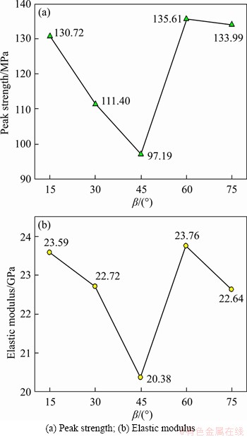
Figure 5 Influence of included angle on mechanical parameters of cross-jointed samples with opening:
In summary, the existence of the opening and cross joints, as well as the variation in the included angle, have a considerable influence on the strength and deformation properties of the cross-jointed samples. These factors will cause the sample to have different bearing capacities and significantly affect the mechanical response behavior of the sample, thus showing significant anisotropic characteristics. These findings strongly support the hypothesis that the mechanical properties of rock masses are weakened in the presence of openings and joints and influenced by the joint angle and thus have important engineering guiding significance for an in-depth understanding of the deformation, bearing capacity, and support and control of the rock surrounding underground openings.
4 Energy evolution analysis
4.1 Energy conversion during failure process
Interpreting the mechanical behavior of rock deformation and failure from the perspective of energy and establishing the correlation between the energy evolution characteristics and rock failure process not only are helpful to elucidating the nature of rock failure but also can theoretically quantify the intensity of rock engineering disasters, providing new ideas for rock theory and engineering practice. According to thermodynamics, energy transformation is the essential feature of the physical processes of matter, and material destruction is a state instability phenomenon driven by energy [3]. Rock continuously accumulates energy under the continuous action of external forces. When the accumulated energy is enough to force joint tips to fracture, cracks initiate and expand. Therefore, the deformation and failure process of rock is essentially a process of internal energy accumulation, dissipation, and release. Moreover, the energy of matter in a thermodynamic system can be transferred, its forms can be converted, and the total amount of the various forms of energy remains unchanged during the conversion and transfer process, as described by the energy conservation principle. During the loading process, the rock system exchanges energy with the outside world, and its energy transformation can be roughly divided into four processes: energy input, energy accumulation, energy dissipation, and energy release [17], as shown in Figure 6.
The work (input energy) done by an external force on rock is first stored in the rock in the form of elastic strain energy. With the continuous input of external energy, the rock begins to deform (such as crack propagation), and part of the energy dissipates in the form of plastic energy and damage energy. In the transformation of energy, the accumulation process of elastic strain energy is reversible. If the external force is unloaded, the elastic strain energy can be released, and the deformation of the rock can be reversed, but the dissipation of plastic energy and damage energy is irreversible. When the input energy is enough to cause the rock to produce fracture surfaces and lose its integral bearing capacity, the rock will rupture and be destroyed, and the remaining energy will be released mostly in the form of kinetic energy, while a small amount of energy will be released in the form of friction energy and radiation energy. The energy transformation involved in the process of the deformation and failure of rock is a dynamic evolution process, which is mainly manifested in the transformation and balance among the mechanical energy, elastic strain energy, plastic energy, and damage energy. During the process of rock deformation and failure, any specific deformation state of the rock corresponds to a specific energy state, which is a function of stress, strain, and time. Note that energy accumulation and dissipation coexist throughout the deformation and failure stage of the rock and that the energy accumulation is greater than the energy dissipation in the pre-peak stage, while the rock is destroyed instantaneously after reaching the peak value, which manifests as an energy release.

Figure 6 Energy transformation of a loaded rock system [17]
4.2 Energy calculation principle
Generally, the deformation characteristics of a rock mass in the process of energy transformation can be divided into reversible deformation and irreversible deformation. Reversible deformation can produce elastic strain energy, while irreversible deformation mainly dissipates energy through plastic deformation, damage, friction, and heat radiation, resulting in energy dissipation. According to the law of thermodynamics and ignoring the heat exchange and acoustic emission energy consumption between the test system and the surrounding environment, it is considered that the mechanical energy input per unit volume is converted into only elastic strain energy, which is stored in the rock mass, and energy dissipated by the occurrence of rock mass damage:
 (1)
(1)
where U is the total strain energy input from external sources; Ue is the releasable elastic strain energy stored in the rock; Ud is the dissipated energy, which is mainly consumed by the internal damage and plastic deformation of rock.
Based on the basic assumption that the elastic energy stored in rock is reversible, the area of the hysteresis loop can reflect the magnitude of the dissipated energy, and the elastic energy and dissipated energy of the sample can be calculated by using the stress-strain curve recorded during a uniaxial loading test. The relationship between the elastic energy density Ue and dissipated energy density Ud of the sample in the unit volume of the loading curve at a certain stress level is shown in Figure 7. The area under the loading curve in the stress-strain curve of the uniaxial loading test is the total energy density U absorbed by the sample, that is, the work done by the testing machine on the sample. The area under the unloading curve is the elastic energy density Ue accumulated by the sample. The dissipated energy density Ud is the difference between U and Ue, that is, the area between the loading and unloading curves, and causes the damage accumulation and plastic deformation inside the sample. According to Hooke��s law, the total energy density U and elastic energy density Ue of the sample under uniaxial compression can be expressed as follows:
 (2)
(2)
 (3)
(3)
where ��1 is the axial principal stress; ��1 is the axial principal strain; E0 is the elastic modulus; Eu is the unloading elastic modulus.

Figure 7 Schematic diagram of energy density calculation of rock under uniaxial compression
4.3 Energy evolution characteristics
In accordance with the stress-strain curve and energy calculation method, the changes in the total energy density, dissipated energy density, and elastic energy density with strain are obtained for the intact sample and the cross-jointed samples containing an opening, as shown in Figure 8. In general, the energy evolution patterns of all the samples are similar but have small differences. The total energy curve, elastic energy curve, and dissipated energy curve of the intact sample are very smooth, while the three energy curves of the jointed samples (especially those with �� of 30��, 45��, and 75��) show significant step-like changes. Based on the evolution law of each energy ratio and slope of the three energy curves of the intact sample with the strain plotted in Figure 8(a), the energy evolution characteristics of the intact sample can be divided into three stages, namely, the initial energy consumption stage, energy stable accumulation stage, and energy fully released stage. For the cross-jointed samples containing an opening, the energy evolution characteristics of the samples can be roughly divided into five stages, as shown in Figures 8(b)-(f).
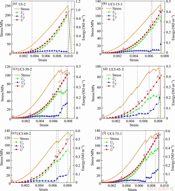
Figure 8 (a) Stress-strain and energy evolution curves of intact sample; Cross-jointed samples containing opening:(b) ��=15��; (c) ��=30��; (d) ��=45��; (e) ��=60��; (f) ��=75��
1) Initial energy consumption stage (OA). With the increase in strain, the total energy curve and elastic energy curve are concave upward, while the dissipated energy curve is S-shaped, and the dissipated energy Ud is larger than the elastic strain energy Ue, which is mainly due to the slight damage of the internal structure of the sample due to the closure and friction of the original microvoid structure in the initial loading stage. Subsequently, the slope of the elastic strain energy curve gradually increases and approaches a fixed value with the increase in strain, while the slope of the dissipated energy curve gradually decreases and approaches zero with the increase in strain, which further reveals that as the original microvoid structure in the specimen gradually completely closes, the specimen structure gradually changes to a denser structure with a higher rigidity, the friction energy consumption in the specimen gradually decreases and the energy accumulation capacity gradually increases. However, the energy conversion efficiency of the specimen is low in this stage, which is mainly characterized by energy dissipation.
2) Energy stable accumulation stage (AB). In this stage, the total energy and elastic energy increase linearly with the strain at a similar rate of increase, and the dissipated energy curve develops horizontally near a small fixed value. In the whole process, the elastic energy Ue is far greater than the dissipated energy Ud. The total energy input from external forces is basically converted into elastic energy and stored in the sample, and the dissipated energy is generally unchanged. The point (point A in this study) where elastic energy and dissipated energy are equal can be used as the dividing line between the initial energy consumption stage and the energy stable accumulation stage.
3) Energy unstable accumulation stage (BC). With a further increase in axial deformation, the energy curves of the jointed samples with an opening show the unstable characteristics of a sudden drop in elastic energy and the sudden increase in dissipated energy. This trend arises because new microcracks are preferentially generated at the joint tips and/or around the opening of the sample due to the stress concentration effect and then propagate, resulting in different degrees of sudden damage to the specimen structure at both the microscale and macroscale; consequently, this damage decreases the specimen strength. At this stage, Ue is still larger than Ud, and energy accumulation is still the main factor in the sample.
4) Energy acceleration dissipation stage (CD). With increasing axial deformation, the number and lengths of the microcracks increase, and the overall strength of the specimen decreases, which leads to a decrease in the elastic energy rate of increase and an increase in the dissipated energy rate of increase at this stage, showing a step-like evolution. This shows that the initiation and propagation of microcracks can not only weaken the mechanical properties of the specimen but also cause the input energy to dissipate via accelerating crack propagation and coalescence, thus weakening the ability of the specimen to accumulate energy.
5) Energy fully released stage (DE). When the stress reaches the peak strength, the total energy and elastic energy curves suddenly drop, and the dissipated energy curve suddenly increases. This reflects that the specimen undergoes a large plastic deformation at this time, and the internal crack instantly results in the sample losing its bearing capacity. The ability of the sample to absorb energy from external sources is obviously decreased, the elastic energy is rapidly transformed into dissipated energy, and the total energy is rapidly reduced and approaches zero. Therefore, the starting point (point D) where the slope of the total energy curve decreases can be regarded as a sign of the initiation of the overall failure of the specimen.
Based on the energy ratio and the slope characteristics of the energy curves, the energy evolution stages of the samples are divided, which can effectively reflect the damage evolution law of the samples during the process of deformation and failure. In addition, the energy evolution curves indicate that due to the uneven distribution of internal stress in the jointed samples with an opening during the process of deformation and failure, remarkable stress concentrations formed in the vicinity of the joint tips and/or the opening. These stress concentrations led to the gradual increase in the damage (mainly the number and length of cracks) and ultimately the overall failure of the sample, reflecting a typical progressive failure. However, when the axial load of the intact specimen reaches its peak strength, microcracks suddenly penetrated through the sample, causing it to rupture, which is a typical failure due to cumulative damage induced by energy mutation.
Under the action of an external load, the stress state of the rock will develop or change from the current stress state to another stress state. The transformation of the stress state corresponds to the deformation and failure of the rock, and the rock eventually forms a new stable state after failure. With the change in the stress state, the rock exhibits the characteristics of energy release at the macroscale. The elastic energy stored in the rock is released, causing the instability and failure of the rock. This is often reflected as the catastrophic failure of a rock mass in engineering, leading to the occurrence of engineering disasters, such as rockburst, caving, and large deformation of surrounding rock. After the energy is released, the internal energy of the rock decreases, and the rock returns to a stable state.
4.4 Evolution mechanism of peak energy
Table 2 shows the total energy, elastic energy, and dissipated energy at the peak point and the total input energy of the intact sample and the cross-jointed samples containing an opening under uniaxial compression. The total input energy of the intact specimen is the largest, which is 1016.25 kJ/m3. The total input energy is in the range of 397.42-569.35 kJ/m3, which is 43.98%-60.89% lower than that of the intact sample. Hence, the total input energy of the cross-jointed samples containing an opening is significantly lower than that of the intact sample, which indicates that the existence of the opening and cross joints in the sample extremely weaken the overall strength of the sample, thus reducing the energy consumption during the failure process of the sample. The peak elastic energy of the intact specimen is the largest, with a value of 912.14 kJ/m3, while the peak elastic energy of the other samples is between 231.75 and 396.51 kJ/m3, showing a reduction of 56.53%-74.59% compared to that of the intact sample. In addition, for the samples with different �� values, the peak elastic energy accounts for 61.36%-92.13% of the measured energy, and the peak dissipated energy accounts for 7.87%-38.64% of the measured energy. That is, the elastic energy is obviously greater than the dissipated energy in these samples, which means that energy storage dominates the energy conversion before peak strength. However, the energy proportions of the samples with different �� values are different, which reflects that the included angle has different influences on the energy accumulation and dissipation of the samples.
Figure 9 shows the curves of the variation in the total energy, elastic energy, and dissipated energy at the peak point and the total input energy with �� during the failure process. It can be found that the peak total energy, peak elastic energy, and total input
energy during failure of the samples all first decrease and then increase with the increase in ��, reaching the minimum values when ��=45��, that is, the above energy curves show an asymmetric V-shaped trend with the increase in ��. However, the dissipated energy increases with the increase in ��. The peak total energy can reflect the energy absorption capacity of the specimen during the loading process before the peak stress. The larger the value is, the more energy the specimen absorbs during deformation and failure. Moreover, the peak elastic energy represents the energy storage limit of the specimen. The greater the energy storage limit, the less likely the specimen is to be damaged by an energy drive. Clearly, the intact sample has the highest strength and the greatest energy storage limit of the samples tested. Compared with the intact sample, the energy storage limit of the cross-jointed samples containing an opening has declined to varying degrees, which indicates that the existence of the opening and cross joints seriously weakens the energy storage limit of those samples. The evolution law of the peak total energy and the peak elastic energy shows that the energy absorption capacity and energy storage limit of a jointed specimen with an opening show a changing trend of first decreasing and then increasing under uniaxial compression when �� increases from 15�� to 75��. However, the peak total energy and the peak elastic energy of the samples with small �� values (15�� and 30��) are smaller than those with large �� (60�� and 75��), which implies that the ability to resist deformation and failure of the samples with �� less than 45�� is weaker than that of the samples with �� greater than 45��, and the sample with �� of 45�� is the most vulnerable to deformation and failure driven by energy. That is, with the increase in ��, the resistance of the cross-jointed samples containing an opening to the energy-driven deformation and failure presents the evolution characteristics of ��high-low-high��.
Table 2 Energy values of intact sample and cross-jointed samples containing an opening


Figure 9 Variation in energy values of cross-jointed samples containing an opening with ��
4.5 Energy distribution characteristics
In a closed test system, the energy that is from external forces and absorbed by the loaded specimen is mainly converted into elastic energy and dissipated energy, and the elastic energy ratio and the dissipated energy ratio will affect the mechanical response behavior of the specimen. The evolutions of the elastic energy ratio and the dissipated energy ratio with the strain and stress of the intact specimen and the cross-jointed samples containing an opening under uniaxial loading are illustrated in Figures 10 and 11, respectively. The energy distribution patterns of each sample are generally similar. In the pre-peak stage, most of the external work (input energy) on the sample is converted into elastic energy and stored in the sample, and the elastic energy accounts for a large proportion of the total energy. Specifically, when the load is applied to the specimen, the ratio of elastic energy is close to 1.0, which is caused by the adjustment of the applied stress of the specimen. Subsequently, due to the closure of the pores and/or microcracks in the sample and the initiation and propagation of microcracks, the proportion of dissipated energy is slightly higher than that of elastic energy. Furthermore, the proportion of elastic energy increases sharply, and the proportion of elastic energy is much larger than that of dissipated energy. Therefore, in the pre-peak stage, the sample mainly accumulates elastic energy but also consumes some energy, which makes the elastic energy ratio and the dissipated energy ratio fluctuate. This stage is a process of energy dynamic transformation.

Figure 10 Changes in elastic energy ratios of tested samples with strain (a) and stress (b)

Figure 11 Changes in dissipated energy ratios of tested samples with strain (a) and stress (b)
The minimum elastic energy ratio of the intact specimen in the initial compaction stage is 13.79%, and the maximum elastic energy ratio at the peak strength is 96.97%. The minimum elastic energy ratios of the cross-jointed samples containing an opening (��=15��, 30��, 45��, 60�� and 75��) in the initial compaction stage are 19.83%, 19.20%, 24.81%, 20.84% and 21.88%, respectively, and the corresponding maximum elastic energy ratios at peak strength are 92.13%, 65.96%, 61.36%, 79.66% and 71.62%, respectively. It can be observed that the existence of the opening and cross joints, as well as the change in ��, have a great influence on the elastic energy ratio before the peak stress, which leads to some differences in the distribution law of external input energy. At peak strength, the maximum elastic energy ratio of the cross-jointed samples containing an opening is generally lower than that of the intact sample, indicating that the energy accumulation efficiency of the cross-jointed samples containing an opening is inferior to that of the intact sample, which further proves that the existence of the opening and cross joints reduces the energy input and energy accumulation efficiency and promotes the dissipation and release of energy due to sample failure.
In the post-peak stage, when the cross-jointed samples containing an opening are near failure, microcracks will be connected along the joint tip and around the opening and spread to form a macroscopic rupture surface, and the axial strain and lateral strain will increase significantly, which will cause the elastic energy accumulated in the sample to be released continuously, resulting in a gradual increase in dissipated energy. Some elastic energy remains in some samples when they are damaged, and more damage must be induced for this elastic energy to be released completely, resulting in a large proportion of elastic energy. When the broken structure of the sample is reconstructed and stabilized, the specimen with a certain residual strength still has the ability to accumulate energy, but the energy accumulation efficiency is far less than that before the peak stress.
Additionally, compared with that of the intact sample, the elastic energy ratio curves of the cross-jointed samples containing an opening show more obvious step-like mutation characteristics, which indicates that the energy distribution law of the cross-jointed samples containing an opening is more complex.
5 Energy criteria for rock failure
The failure of rock due to a local high stress does not necessarily lead to the overall failure of the rock. The current stress strength theory and failure criterion have difficulty effectively analyzing the complex strength change characteristics and overall failure behavior of rock. For a jointed rock mass containing an opening, stress concentration occurs at the joint tips and around the opening during the deformation process. Crack initiation and propagation in the stress concentration area cause energy dissipation, and the dissipated energy is converted into the surface energy of crack propagation. Energy dissipation is the essential attribute of rock deformation and failure, which reflects the process of the continuous development, strength reduction, and ultimate loss of microdefects in the rock. Therefore, energy dissipation is directly related to damage and strength loss, and the amount of energy dissipation reflects the degree of the original strength attenuation [3]. Due to the dominant guiding effect of the opening and joints, the energy release is relatively concentrated and rapid, and the dissipated energy evolves in a ��step�� shape. The process of crack propagation and evolution in a jointed rock mass containing an opening is the process of not only its failure but also the sudden change in its internal energy transformation, which can reveal the mechanism of initiation and propagation of cracks from the perspective of energy mutation.
The energy consumption ratio, K, is defined as the ratio of dissipated energy to elastic energy and characterizes the internal damage accumulation of the loaded sample, which can reflect the energy consumption and energy storage state during the process of deformation and failure of the sample. K can be calculated as:
 (4)
(4)
where K<1 means that the elastic energy accumulated in the loaded sample is much larger than the dissipated energy and that the loaded sample is in a relatively stable state; K=1 indicates that the loaded sample is in a critical stable state, and K>1 represents the unstable state of the loaded sample.
Figure 12 shows the relationship between the energy consumption ratio K and the stress-strain curve of the intact sample and the cross-jointed samples containing an opening under uniaxial loading. It can be observed that the energy consumption ratio K of the different types of samples in the initial compaction stage first increases and then decreases with strain and sharply increases when the samples fail. In the initial compression stage and elastic deformation stage, the energy consumption ratio is K=1. Moreover, the variation trends of the energy consumption ratios with the strain of the cross-jointed samples containing an opening are relatively consistent and are only slightly affected by the change in the included angle of the cross joints.
The intact specimen dissipates energy in the initial compaction stage due to the closure of microcracks, and the rate of increase in the dissipated energy is greater than that in the elastic energy, so the energy consumption ratio K increases sharply, but the loaded specimen remains in a stable state. After the energy consumption ratio increases to approximately 6.3, with the gradual closure of the microcracks, the rate of increase in the dissipated energy slows, the rate of increase in the elastic energy increases gradually, and the elastic energy mainly accumulates; thus, the corresponding energy consumption ratio K gradually decreases and to a stable value (K<1), indicating that the sample is in a stable state. Finally, when the loaded sample ruptures within a short time after the macroscopic fracture surface is generated at the peak point, the elastic energy accumulated in the loaded sample is released rapidly, and the dissipated energy increases sharply, which causes the energy consumption ratio K to suddenly increase to the maximum value (K is far greater than 1) and indicates that the intact sample is destroyed.

Figure 12 (a) Stress-strain curves and evolution laws of energy consumption ratio with strain of the intact sample; Cross-jointed samples containing opening: (b) ��=15��; (c) ��=30��; (d) ��=45��; (e) ��=60��; (f) ��=75��
For the cross-jointed samples containing an opening, in the initial compaction stage, the energy consumption ratio K increases to a large value and then decreases gradually, keeping K within the range of less than 1. The maximum energy consumption ratio K of the cross-jointed samples containing an opening in this stage is smaller than that of the intact sample (Figure 13), which may be caused by the initial damage of the cross-jointed samples containing an opening due to the prefabricated openings and cross joints in the samples. In the stable crack propagation stage and unstable crack propagation stage, the crack initiation and propagation at the tips of the two groups of cross joints, around the opening, and in the rock bridge area are more severe than they are in earlier stages, which leads to an abrupt change in the rate of change in the energy consumption ratio (dK/d��). This indicates that the cracks in the stress concentration areas such as the joint tips and in the vicinity of the opening begin to initiate and propagate. Finally, the rate of change in the energy consumption ratio (dK/d��) sharply increases (dK/d�� goes to positive infinity), and the energy consumption ratio K increases to the maximum value (K is far greater than 1), which means that the cracks basically penetrate the samples, and the samples lose their bearing capacity.

Figure 13 Evolution laws of energy consumption ratio with strain of tested samples
In summary, the continuous change in the rate of change in the energy consumption ratio (dK/d��) can be used as the criterion of crack initiation and propagation, and the subsequent sharp change in the rate of change in the energy consumption ratio (dK/d��) can be regarded as the criterion of instability and failure of the sample. By analyzing the energy transfer and transformation during the process of rock deformation and failure in detail, the energy criterion of rock instability and failure established from the perspective of energy change can reflect the failure law of rock more accurately and provide a basis for judging overall stability in rock engineering.
6 Discussion
The deformation and failure processes of the cross-jointed samples containing an opening have similar stress-strain characteristics (Figure 4(b)), and their deformation and failure modes can be regarded as stress-control types. That is, the elastic strain energy of rocks increases in the loading stage and suddenly releases when the peak stress is reached, resulting in rapid failure of the samples. In the process of loading, the external energy is gradually transformed into the internal energy of the samples. The initiation, propagation, and coalescence of cracks in the samples are driven by the internal energy, and the change law of internal energy is directly related to the failure of the samples. The cross-jointed samples containing an opening have different stress distribution patterns due to the differences in the joint geometries, which leads to great differences in the energy storage and energy release capabilities among the samples and thus their failure modes (Figure 14). Among the specimens tested, there are some differences in the shape, density, and distribution position of cracks during failure, which is closely correlated with the internal stress distribution in each specimen and reflects the difference in energy required for specimen failure to a certain extent. The development of cracks is driven by energy. During crack propagation, strain energy gradually accumulates at the crack tip, and an open crack is formed after reaching the energy storage limit, that is, the elastic strain energy and dissipated energy jointly determine the failure of the specimen. According to the previous analysis, there is a good correspondence between the macroscopic fracture morphology of the specimen and the energy required for specimen failure, which reflects the anisotropy of the failure energy and fracture characteristics of the jointed rock mass during loading. On the other hand, the macroscopic failure modes of the samples (Figure 14) show that the crack propagation modes of the jointed samples are strongly dominated by the cross joint structure and reflect that different macroscopic failure modes strictly determine the anisotropy of the energy storage and energy consumption of the samples. Therefore, the deformation and failure of rocks can be effectively described from the perspective of energy.
Generally, the failure of a small rock specimen is a mechanical state corresponding to the change or complete reduction in its energy storage capacity, while the failure of large-scale rock mass engineering occurs in an engineering state corresponding to the change or complete reduction in its load carrying capacity [18]. The direct cause of instability of rock mass engineering is due to the failure of rock materials, but the failure of rock materials does not necessarily lead to the instability and failure of rock mass engineering. Actual rock mass engineering is practiced in natural strata, which have different scales of joints, fissures, and other weak structural planes due to its geological history, excavation disturbance, and other factors, weakening the strength and stability of the rock mass to a certain extent. Moreover, a rock mass in an area affected by underground engineering is constrained by a larger range of rock mass systems, with unknown parameters. Therefore, it is impossible to accurately describe the instability and failure of the whole structure in rock mass engineering with a deterministic mathematical and mechanical model and corresponding failure criteria. The excavation process of underground rock mass engineering can be regarded as a process of both energy storage and energy dissipation. The process of rock mass engineering from a stable equilibrium state to a critical state before instability can be regarded as a quasi-static process. Hence, the whole project affected area can be regarded as a system, and the stability of the studied area can be investigated through the change in the strain energy of the system [19].
Additionally, openings are generally an indispensable supporting engineering structure in underground rock engineering, and the stability of openings may affect the safe and efficient operation of the entire underground engineering system. With the deep expansion of underground engineering, the stress in the rock increases, and the dynamic disasters induced by underground engineering excavation frequently occur. Under the conditions of deep rock under a high stress and with a complex geological structure, the energy accumulated in the surrounding rock of the opening increases significantly, which provides an energy source that may drive the occurrence of engineering disasters. In addition, in a high-stress environment, the energy accumulated in the surrounding rock of the opening can be released rapidly, thus inducing sudden and destructive disasters (such as rockburst), which makes disaster prediction more difficult. Therefore, for the stability control of the surrounding rock of a deep opening under high-stress conditions, the energy accumulation and release in the process of engineering disaster should be fully considered to reduce the accumulated energy in the surrounding rock of the opening as much as possible, and some measures may need to be taken to reduce the speed of the release of the accumulated energy in the surrounding rock. To that end, control measures for the stability of the surrounding rock should be implemented from at least two aspects: 1) Reducing energy accumulation. By optimizing the shape and size of the cross-section and reducing the excavation rate, the excavation scheme of the opening should be comprehensively determined to reduce the local high energy accumulation in the surrounding rock caused by excavation. Furthermore, loose blasting technology can be used around the opening in the surrounding rock where it is easy to accumulate high energy and form a fissure development body. 2) Reducing the energy release rate. Adopting energy-absorbing bolts, shotcrete, steel mesh, and other supporting methods to absorb the energy released during engineering disasters as much as possible, thereby reducing the energy release rate.

Figure 14 Failure pattern of tested samples:
7 Conclusions
The peak strength and elastic modulus of the cross-jointed samples containing an opening decrease with increasing �� from 15�� to 45��, reach their minimum values at 45��, and increase with increasing �� from 45�� to 75��, clearly showing nonlinear variation characteristics.
According to the change law of the energy ratio and slope of each of the three energy curves with the strain of the cross-jointed samples containing an opening, the energy evolution characteristics of the samples can be roughly divided into five stages: an initial energy consumption stage, energy stable accumulation stage, energy unstable accumulation stage, energy acceleration dissipation stage, and energy fully released stage, which reflects a typical progressive damage mode.
The peak total energy, peak elastic energy, and the total input energy during failure of the cross-jointed samples containing an opening all first decrease and then increase with the increase in ��, reaching their minimum values when �� is 45��. Thus, these energy curves show asymmetric V-shaped evolutions with the increase in ��. However, the dissipated energy generally increases with the increase in ��. Before the peak stress, most of the external work on the sample is converted into elastic energy and stored in the sample, accounting for a large proportion of the total energy. In the peak or post-peak stage, the proportion of dissipated energy increases gradually or suddenly. The opening and cross joints have an obvious energy weakening effect on the sample. The change in the included angle of the cross joints has a great influence on the elastic energy ratio of the samples before the peak stress, which leads to some differences in the distribution laws of the input energy among these samples.
The energy consumption ratio changes continuously and suddenly near the peak point, which indicates crack growth and potential failure of the specimen. The continuous change in the rate of change in the energy consumption ratio can be used as the criterion of crack initiation and propagation, and the subsequent sharp change in the rate of change in the energy consumption ratio can be regarded as the criterion of instability and failure of the cross-jointed samples containing an opening. The deformation and failure process of a loaded specimen is essentially a process of energy dissipation and release, and instability and failure are caused by the instantaneous release of elastic energy accumulated in the specimen.
Contributors
The overarching research goals were developed by LI Peng and CAI Mei-feng. LI Peng designed the project and analyzed the calculated results. The initial draft of the manuscript was written by LI Peng and checked by CAI Mei-feng. All authors replied to reviewers�� comments and revised the final version.
Conflict of interest
LI Peng and CAI Mei-feng declare that they have no conflict of interest.
References
[1] YANG Sheng-qi, YIN Peng-fei, ZHANG Yuan-chao, CHEN Miao, ZHOU Xiao-ping, JING Hong-wen, ZHANG Qiang-yong. Failure behavior and crack evolution mechanism of a non-persistent jointed rock mass containing a circular hole [J]. International Journal of Rock Mechanics and Mining Sciences, 2019, 114: 101-121. DOI: 10.1016/j.ijrmms.2018.12.017.
[2] LI De-xing, WANG En-yuan, KONG Xiang-guo, ALI M, WANG Dong-ming. Mechanical behaviors and acoustic emission fractal characteristics of coal specimens with a pre-existing flaw of various inclinations under uniaxial compression [J]. International Journal of Rock Mechanics and Mining Sciences, 2019, 116: 38-51. DOI: 10.1016/j.ijrmms. 2019.03.022.
[3] XIE He-ping, JU Yang, LI Li-yuan. Criteria for strength and structural failure of rocks based on energy dissipation and release principles[J]. Chinese Journal of Rock Mechanics and Engineering, 2005, 24(17): 3003�C3010. DOI: 10.3321/ j.issn:1000-6915.2005.17.001. (in Chinese)
[4] BAGDE M N, PETROS V. Fatigue and dynamic energy behaviour of rock subjected to cyclical loading [J]. International Journal of Rock Mechanics and Mining Sciences, 2009, 46(1): 200-209. DOI: 10.1016/j.ijrmms.2008.05.002.
[5] MENG Qing-bin, ZHANG Ming-wen, HAN Li-jun, PU Hai, NIE Tao-yi. Effects of acoustic emission and energy evolution of rock specimens under the uniaxial cyclic loading and unloading compression [J]. Rock Mechanics and Rock Engineering, 2016, 49: 3873-3886. DOI: 10.1007/s00603-016-1077-y.
[6] CHEN Zi-quan, HE Chuan, WU Di, XU Guo-wen, YANG Wen-bo. Fracture evolution and energy mechanism of deep-buried carbonaceous slate [J]. Acta Geotechnica, 2017, 12: 1243-1260. DOI: 10.1007/s11440-017-0606-5.
[7] MENG Qing-bin, ZHANG Ming-wei, ZHANG Zhi-zhen, HAN Li-jun, PU Hai. Experimental research on rock energy evolution under uniaxial cyclic loading and unloading compression [J]. Geotechnical Testing Journal, 2018, 44: 717-729. DOI: 10.1520/GTJ20170233.
[8] TANG Yang, OKUBO S, XU Jiang, PENG Shou-jian. Experimental study on damage behavior of rock in compression�Ctension cycle test using 3D digital image correlation [J]. Rock Mechanics and Rock Engineering, 2019, 52: 1387-1394. DOI: 10.1007/s00603-018-1685-9.
[9] CHEN Zi-quan, HE Chuan, MA Gao-yu, XU Guo-wen, MA Chun-chi. Energy damage evolution mechanism of rock and its application to brittleness evaluation[J]. Rock Mechanics and Rock Engineering, 2019, 52: 1265-1274. DOI: 10.1007/s00603-018-1681-0.
[10] WANG Chun-lai, HE Bin-bin, HOU Xiao-lin, LI Jie-yu, LIU Lu. Stress�Cenergy mechanism for rock failure evolution based on damage mechanics in hard rock [J]. Rock Mechanics and Rock Engineering, 2020, 53: 1021-1037. DOI: 10.1007/ s00603-019-01953-y.
[11] LI Peng, REN Fen-hua, CAI Mei-feng, GUO Qi-feng, WANG Hao-fei, LIU Kang. Investigating the mechanical and acoustic emission characteristics of brittle failure around a circular opening under uniaxial loading [J]. International Journal of Minerals, Metallurgy and Materials, 2019, 26: 1217-1230. DOI: 10.1007/s12613-019-1887-5.
[12] LI Yin-ping, CHEN Long-zhu, WANG Yuan-han. Experimental research on pre-cracked marble under compression [J]. International Journal of Solids and Structures, 2005, 42: 2505-2516. DOI: 10.1016/j.ijsolstr.2004.09.033.
[13] LI X, ZHOU T, LI D. Dynamic strength and fracturing behavior of single-flawed prismatic marble specimens under impact loading with a split-hopkinson pressure bar [J]. Rock Mechanics and Rock Engineering, 2017, 50: 29-44. DOI: 10.1007/s00603-016-1093-y.
[14] YANG Sheng-qi, HUANG Yan-hua. An experimental study on deformation and failure mechanical behavior of granite containing a single fissure under different confining pressures [J]. Environmental Earth Sciences, 2017, 76: 364. DOI: 10.1007/s12665-017-6696-4.
[15] SAGONG M, PARK D, YOO J, LEE J S. Experimental and numerical analyses of an opening in a jointed rock mass under biaxial compression [J]. International Journal of Rock Mechanics and Mining Sciences, 2011, 48: 1055-1067. DOI: 10.1016/j.ijrmms.2011.09.001.
[16] BIENIAWSKI Z T, BERNEDE M J. Suggested methods for determining the uniaxial compressive strength and deformability of rock materials: Part 1. Suggested method for determination of the uniaxial compressive strength of rock materials [J]. International Journal of Rock Mechanics and Mining Sciences and Geomechanics Abstracts, 1979, 16: 137-140. DOI: 10.1016/0148-9062(79)91450-5.
[17] ZHANG Zhi-zhen, GAO Feng. Research on nonlinear characteristics of rock energy evolution under uniaxial compression [J]. Chinese Journal of Rock Mechanics and Engineering, 2012, 31(6): 1198-1207. DOI: 10.3969/ j.issn.1000-6915.2012.06.015. (in Chinese)
[18] ZHU De-ren. Criterion for rock project failure [J]. Journal of China Coal Society, 1994, 19(1): 15-20. DOI: 10.13225/ j.cnki.jccs.1994.01.003. (in Chinese)
[19] CAI Mei-feng, KONG Guang-ya, JIA Li-hong. Criterion of energy carastrophe for rock project system failure in underground engineering [J]. Journal of University of Science and Technology Beijing, 1997, 19(4): 325-328. DOI: 10.13374/j.issn1001-053x.1997.04.023. (in Chinese)
(Edited by ZHENG Yu-tong)
���ĵ���
��������½���Χ�ҵ������ݻ����Ƽ��ƻ���
ժҪ�����ڵ�������������ʯ����ԭ�����о��˺���������������ڱ����ƻ������е������ݻ����ƺ��ƻ���������������������ݻ��������ڵ��͵����˽����ƻ�ģʽ�������ķ�ֵ���������������ܺ��ƻ�ʱ����������������Ž��������нǵ�����������ȼ�С����������ƣ��ڰ�н�Ϊ45��ʱ��С������ɢ�����Ű�нǵ����ӳ��������ơ����ͽ�������Ĵ���������������ʯ�Ĵ��������������нǵı仯�Է�ǰ�ĵ����ܱ���Ӱ��ϴ������������ķ�����ɴ���һ�����졣������ɢ�ȱ仯�ʵ�����ͻ������ļ���ͻ��ɷֱ���Ϊ����������������չ�Լ�ʧ���ƻ����оݡ�
�ؼ��ʣ������ݻ����ƣ��ƻ��������壻����������������
Foundation item: Project(FRF-TP-20-041A1) supported by the Fundamental Research Funds for the Central Universities, China; Projects(2016YFC0600801, 2017YFC0804103) supported by the State Key Research Development Program of China; Projects(51774022, 52074020) supported by the National Natural Science Foundation of China
Received date: 2021-03-13; Accepted date: 2021-04-05
Corresponding author: LI Peng, PhD, Lecturer; Tel: +86-10-62333700; E-mail: pengli@ustb.edu.cn; ORCID: https://orcid.org/0000-0003-0913-872X
Abstract: The object of this article is to investigate the energy evolution mechanism and failure criteria of cross-jointed samples containing an opening during deformation and failure based on the uniaxial compression test and rock energy principle. The results show that the energy evolution characteristics of the samples correspond to a typical progressive damage mode. The peak total energy, peak elastic energy, and total input energy of the samples all first decrease and then increase with an increase of half of the included angle, reaching their minimum values when this angle is 45��, while the dissipated energy generally increases with this angle. The existence of the opening and cross joints can obviously weaken the energy storage capacity of the rock, and the change in the included angle of the cross joint has a great influence on the elastic energy ratio of the sample before the peak stress, which leads to some differences in the distribution laws of the input energy. The continuous change and the subsequent sharp change in the rate of change in the energy consumption ratio can be used as the criteria of the crack initiation and propagation and the unstable failure of the sample, respectively.
