
J. Cent. South Univ. (2012) 19: 1182-1188
DOI: 10.1007/s11771-012-1126-y![]()
Nonlinear static response of piezoelectric plates considering electro-mechanical coupling
B. Behjat, M. R. Khoshravan
Mechanical Engineering Department, Tabriz University, Tabriz, Iran
? Central South University Press and Springer-Verlag Berlin Heidelberg 2012
Abstract:
Nonlinear static analysis of piezoelectric plates has been carried out using nonlinear finite element method considering electro-mechanical coupling. The geometrical nonlinearity has been taken into account and electric potential is assumed to be quadratic across the plate thickness. The governing equations are obtained using potential energy and Hamilton��s principle that includes elastic and piezoelectric effects. The finite element model is derived based on constitutive equation of piezoelectric material accounting for coupling between elasticity and electric effect using higher order plate elements. Results are presented for piezoelectric plate under different mechanical boundary conditions. Numerical results for the plate are given in dimensionless graphical forms. Effects of boundary conditions on linear and nonlinear response of the plate are also studied. The numerical results obtained by the present model are in good agreement with the available solutions reported in the literature.
Key words:
1 Introduction
Based on the coupled mechanical and electrical properties, piezoelectric structures have found much applications as sensors and actuators for the purpose of monitoring and controlling the response of structures, respectively [1]. Also, piezoelectric materials have new applications for micro-electromechanical systems and intelligent material systems, especially in the medical and aerospace industries [2]. Here, some of the works that have been done in this field are mentioned. KOOGL and BUCALEM [3-4] introduced a new class of accurate and reliable piezoelectric shell elements for piezoelectric structures. The formulations are based upon the Reissner�CMindlin assumptions and they used mixed interpolation of tonsorial components (MITC) approach to eliminate the shear locking. LU et al [5] presented a new method for the derivation of exact solutions of a simply supported rectangular functionally graded piezoelectric material (FGPM) plate or laminate by a semi-analytical method. A theoretical study is presented for analyzing the coupled non-linear response of shallow doubly curved adaptive laminated piezoelectric shells undergoing large displacements and rotations by the VARELIS et al [6]. BUTZ et al [7] investigated three-dimensional piezoelectric beam formulation and its finite element implementation. The developed model considers geometrically and materially non-linear effects and formulation based on Timoshenko beam theory. A theoretical method is presented for analyzing the coupled non-linear response of shallow doubly curved adaptive laminated piezoelectric shells undergoing large displacements and rotations by the VARELIS and SARAVANOS [8]. BEHJAT et al [9-10] presented a comprehensive study on static, dynamic and free vibration response of FGPM panels using finite element method under different sets of mechanical, thermal and electrical loadings. TANVEER and SING [11] presented a numerical approach for linear and geometrically nonlinear forced vibrations of laminated composite plates with piezoelectric layers. A finite element model based on the first order shear deformation theory (FSDT) has been developed for the static flexural shape and vibration control of a glass fibre/polyester composite plate bonded with piezoelectric actuator and sensor patches by THINH and NGOC [12].
In this work, the nonlinear static response of piezoelectric plates under the mechanical loading is investigated. Geometrically nonlinear behavior of the plate has been taken into account. The analysis is carried out using finite element method and higher order elements are used to model the plate. Extensive numerical results are presented in graphical forms to give an insight into the influences of material composition and the type of boundary condition on the nonlinear static response of piezoelectric plate as an example.
2 Problem explanations
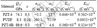
In this section, the geometry, boundary condition and materials of the piezoelectric plate are explained. The boundary conditions of the plate under current consideration are two edges free and others simply supported (SFSF) in the first case and two edges free and two clamped (CFCF) in the second case (Fig. 1). The piezoelectric materials used are PZT-4, PZT-6B and PVDF and their properties are listed in Table 1 [13]. The geometry of the plate is described in Cartesian coordinates (x, y, z). The dimensions of the plate are defined by the same length and width of a=b=400 mm and thickness of h=15 mm, as described in Fig. 1. The static response of piezoelectric plates under the mechanical loadings is investigated. Geometrically nonlinear behavior of the plate has been taken into account and the analysis is carried out using finite element method.
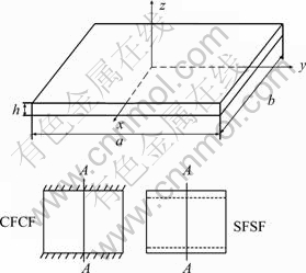
Fig. 1 Plate geometry and boundary conditions
Table 1 Properties of piezoelectric materials [13]
3 Theoretical formulations
3.1 Constitutive relations
The linear constitutive relations describing the electrical and mechanical interaction for piezoelectric materials can be expressed as [4]
S=Q��-Ee (4)
D=e��+KE (5)
where S and �� are the stress and strain tensors respectively, D is the electrical displacement vector, ![]() is the electrical field vector and �� is the electrical potential, Q is the elasticity matrix, e is the piezoelectric constant matrix and K is the dielectric permittivity coefficient matrix.
is the electrical field vector and �� is the electrical potential, Q is the elasticity matrix, e is the piezoelectric constant matrix and K is the dielectric permittivity coefficient matrix.
3.2 Variational formulation
The potential energy H stored in a lamina considering the strain energy, piezoelectric energy and electrical energy of various components is given by [12]
![]() (6)
(6)
where
![]() (7)
(7)
![]() (8)
(8)
Hamilton��s principle for the plate can be written as
![]() (9)
(9)
where t1 and t2 denote two arbitrary time values, �� is the variational operator and Wext is the work done by external forces. It is worth to note that the variable t is a virtual variable and our final equations will not depend on time. The variation of these parameters can be written as
![]()
![]() (10)
(10)
where q is the electrical surface charge, fb, fc and fs represent the body force, concentrated load and specified surface traction, respectively, and 0V and 0s denote the volume and surface of the element in the first step of the analysis. To obtain the proper form of the Hamilton��s principle, the strain and electric field are divided into two parts [14]:
![]() (11a)
(11a)
![]() (11b)
(11b)
It is worth to note that all parameters in time t are known. Also it is obvious that,
![]() (12a)
(12a)
![]() (12b)
(12b)
Also, the strain tensor can be written in linear and nonlinear parts as
![]() (13)
(13)
where 0e and 0�� are the linear and nonlinear parts of the strain tensor, respectively. Substituting Eqs. (11), (12) and (13) into Eq. (6) and neglecting the higher order terms, the potential energy of the plate in variational form can be written as

![]() (14)
(14)
Substituting Eqs. (10), (11) and (14) into Eq. (9) yields the final variational form of the problem which is used to obtain the stiffness matrix of each element.
3.3 Finite element modeling
The nonlinear strain tensor that takes into account the geometric nonlinear terms can be defined as
![]()
![]() (15)
(15)
Also, the relationship between the electric potential and electric field in this coordinate system is defined as
 (16)
(16)
The displacement field at the element can be defined in terms of nodal variables as follows [12]:
![]() (17)
(17)
where ![]() is the unit vector in each node that is normal to the mid-surface of the element, hk is the shape function [15], z is the dimensionless coordinate line in x3 direction,
is the unit vector in each node that is normal to the mid-surface of the element, hk is the shape function [15], z is the dimensionless coordinate line in x3 direction, ![]() for i=1,��,16 are generalized nodal displacements, and ak is the thickness of the plate in each node. Also, the electric potential through the thickness has the quadratic form [4] and can be written as
for i=1,��,16 are generalized nodal displacements, and ak is the thickness of the plate in each node. Also, the electric potential through the thickness has the quadratic form [4] and can be written as
![]() (18)
(18)
where ��e={��1, ��, ��16}T are the nodal electric potentials in a local coordinate system. The linear part of Green-Lagrange strain tensor can be written in terms of nodal variables as
![]() (19)
(19)
And the electric field vector E can be expressed in terms of nodal variables as
![]() (20)
(20)
The B�� and BL are matrices that show the relationship among displacements and electrical potential versus strain and electric field, respectively. Substituting Eqs. (19) and (20) into Eq. (9) yields the final element equation as
![]() (21a)
(21a)
![]() (21b)
(21b)
where ENL, KNL, KL, Ku��, and K�զ� are the nonlinear piezoelectric, nonlinear stiffness, linear stiffness, linear piezoelectric and permittivity stiffness matrices, respectively. Fm and Fp are the load vectors in local co-ordinate system. Also, the mesh model of the plate is shown in Fig. 2.
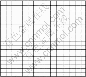
Fig. 2 Mesh model of plate
4 Results and numerical examples
Although the theoretical solutions for one problem have great advantages compared with numerical methods, we used finite element method to solve this problem for some reasons, such as having many limitations on the boundary conditions and applied loading to solve the problem by the theoretical methods, having several methods of the solution for one problem to compare the results and trusting on the obtained results and finally adding this new piezoelectric shell element to commercial softwares.
The purpose of this work is to apply the proposed plate element to the linear and nonlinear static analysis of a plate under the mechanical loading. In order to verify the accuracy and effectiveness of finite element model based on the theory presented above, the numerical results obtained by the present model were compared with available solutions reported in the literature. It is worth to note that the Total Lagrangian method is used to formulate the equations and modified Newoton-Raphson method is used to solve the nonlinear equations.
4.1 Comparison studies
To ensure the efficiency and accuracy of the present methodology, three illustrative examples were solved for linear static response of simply supported piezoelectric plates.
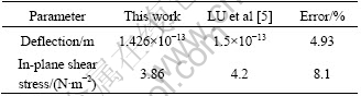
Example 1: The linear deflection and stresses of the simply supported piezoelectric plate are presented. The results are compared with the data reported by LU et al [5]. The square plate consists of PZT-4 material and dimensions are: a=b=1 m and h=0.1 m. The plate is subjected to sinusoidal mechanical load on the top surface by![]() In Table 2, the deflection and in-plane shear stresses (��xy) at the location x=y=0.25a of the plate are shown. From these results, it can be observed that the present analysis is in good agreement with the results of LU et al [5].
In Table 2, the deflection and in-plane shear stresses (��xy) at the location x=y=0.25a of the plate are shown. From these results, it can be observed that the present analysis is in good agreement with the results of LU et al [5].
Table 2 Deflection and stress at location x=y=0.25a in plate and comparison with results of LU et al [5]
Example 2: In this example, we compare the nonlinear static response of the isotropic square plate. The dimensions of the plate are defined by the length a=b=10 254 mm, and thickness h=1 25.4 mm. The material properties of plate are: E=53.74 GPa and ��=0.3. The plate boundary conditions are simply supported in four edges. The plate is subjected to dimensionless uniformly distributed mechanical load, ![]() The curve of central point deflection of the plate is plotted in Fig. 3 and compared with the results of ZHAO and LIEW [16]. From these results, it can be observed that the present analysis results are in good agreements with the results of ZHAO and LIEW [16].
The curve of central point deflection of the plate is plotted in Fig. 3 and compared with the results of ZHAO and LIEW [16]. From these results, it can be observed that the present analysis results are in good agreements with the results of ZHAO and LIEW [16].
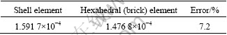
Example 3: An finally, we compare the results of the proposed new shell elements with the 20 node brick elements. The plate consists of PZT-4 material with length and width of a=b=400 mm and thickness of h=15 mm. The plate is subjected to uniform voltage ��=200 V. The maximum deflection of the plate in electrical loading is shown as dimensionless parameter, ![]() in Table 3. The result is compared with 3-D calculations obtained by the 20-node hexahedral (brick) elements. It is observed that the results of two types of elements are in good agreement with each other.
in Table 3. The result is compared with 3-D calculations obtained by the 20-node hexahedral (brick) elements. It is observed that the results of two types of elements are in good agreement with each other.
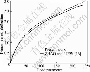
Fig. 3 Nonlinear deflection of plate and comparison with results of ZHAO and LIEW [16]
Table 3 Comparison of dimensionless maximum deflection for shell and brick elements
4.2 Linear analysis
In the first step, we present the linear results of the piezoelectric plate that is subjected to mechanical loading. The influence of the electro-mechanical coupling is studied on the PZT-4, PZT-6B and PVDF materials. The plate is subjected to uniformly distributed load q=500 kPa. Figure 4 shows the dimensionless deflection of the plate ![]() along the line A-A of the plate (see Fig. 1) for two kinds of boundary conditions. It can be observed that the deflection of the PVDF plate is higher than others. This is intuitively correct as the elastic modulus of PVDF is lower than that of PZT-4 and PZT-6B. From Fig. 4, it is obvious that the elastic modulus is the main parameter that affects the deflection of the plate.
along the line A-A of the plate (see Fig. 1) for two kinds of boundary conditions. It can be observed that the deflection of the PVDF plate is higher than others. This is intuitively correct as the elastic modulus of PVDF is lower than that of PZT-4 and PZT-6B. From Fig. 4, it is obvious that the elastic modulus is the main parameter that affects the deflection of the plate.
Figure 5 depicts the maximum in-plane normal stresses ��xx for two different boundary conditions. It is shown only in one curve, because the stresses in isotropic structures don��t depend on the material. Figure 6 shows the electrical potential versus dimensionless length for CFCF and SFSF boundary conditions. The electrical potential is shown in dimensionless form as ![]() , where k33 and e31 are parameters of PZT-4 material. It is seen that the electric field of PVDF plate has the lowest value, while PZT-4 has the highest value and the mean value belongs to the PZT-6B material. This can be explained that there are two parameters that affect the values of electric field. The first one is the deflection of the plate (because the electric field depends on strains and consequently deflection of the plate (Eq. (1)). The second parameter is the dielectric permittivity coefficient matrix. The lower values of electric field in PZT-6B from PZT-4 can be explained by the deflection of plates with these materials. As the displacement of the PZT-6B is less than PZT-4, the induced voltage is lower in PZT-6B. But for PVDF material, the main parameter that dominates the behavior of plate is the dielectric permittivity coefficient matrix and as seen from Table 1, the permittivity coefficient of PVDF is very less than others and this causes the decrease of the induced voltage from PZT-6B to the PVDF plate.
, where k33 and e31 are parameters of PZT-4 material. It is seen that the electric field of PVDF plate has the lowest value, while PZT-4 has the highest value and the mean value belongs to the PZT-6B material. This can be explained that there are two parameters that affect the values of electric field. The first one is the deflection of the plate (because the electric field depends on strains and consequently deflection of the plate (Eq. (1)). The second parameter is the dielectric permittivity coefficient matrix. The lower values of electric field in PZT-6B from PZT-4 can be explained by the deflection of plates with these materials. As the displacement of the PZT-6B is less than PZT-4, the induced voltage is lower in PZT-6B. But for PVDF material, the main parameter that dominates the behavior of plate is the dielectric permittivity coefficient matrix and as seen from Table 1, the permittivity coefficient of PVDF is very less than others and this causes the decrease of the induced voltage from PZT-6B to the PVDF plate.
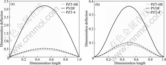
Fig. 4 Deflection of plate in linear analysis for SFSF (a) and CFCF (b) boundary conditions through line A-A
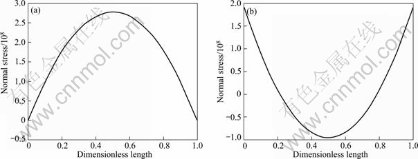
Fig. 5 Maximum in-plane normal stress ��xx in linear analysis for SFSF (a) and CFCF (b) boundary conditions through line A-A
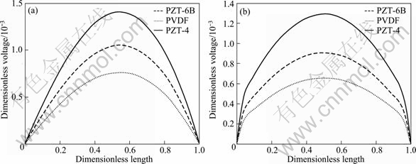
Fig. 6 Dimensionless voltage of piezoelectric plate for SFSF (a) and CFCF (b) boundary conditions through line A-A
4.3 Nonlinear analysis
Figure 7 depicts the maximum deflection of the plate versus load parameter ![]() in nonlinear analysis. It can be seen that by increasing the elastic modulus, the central deflection of the plates decreases for the same load. This can be seen in linear analysis. Also by increasing the load, the nonlinear response deviates from linear much more. This is true because by increasing the deflection, nonlinear stiffness matrix [KNL], has much influence on the response of the plate and stiffness of the plate decreases and subsequently deflection of the plate increases in a lower rate. Figure 8 shows the dimensionless electric potential versus the load parameter of the plate for two boundary conditions. It can be observed that the behavior of the electrical potential in nonlinear analysis is the same as linear behavior. This means that the induced electrical potential in PZT-4 material is higher than others. Also the PVDF has the lowest values of electrical potential in linear analysis. It is seen that, the induced electrical potential of the plate with SFSF boundary condition is higher than that of CFCF plate. The reason is that the deflection of the SFSF plate is higher than CFCF plate.
in nonlinear analysis. It can be seen that by increasing the elastic modulus, the central deflection of the plates decreases for the same load. This can be seen in linear analysis. Also by increasing the load, the nonlinear response deviates from linear much more. This is true because by increasing the deflection, nonlinear stiffness matrix [KNL], has much influence on the response of the plate and stiffness of the plate decreases and subsequently deflection of the plate increases in a lower rate. Figure 8 shows the dimensionless electric potential versus the load parameter of the plate for two boundary conditions. It can be observed that the behavior of the electrical potential in nonlinear analysis is the same as linear behavior. This means that the induced electrical potential in PZT-4 material is higher than others. Also the PVDF has the lowest values of electrical potential in linear analysis. It is seen that, the induced electrical potential of the plate with SFSF boundary condition is higher than that of CFCF plate. The reason is that the deflection of the SFSF plate is higher than CFCF plate.
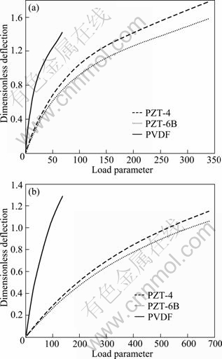
Fig. 7 Maximum deflections of plate versus load parameter in nonlinear analysis for SFSF (a) and CFCF (b) boundary conditions
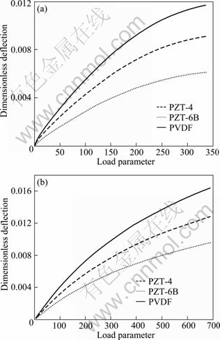
Fig. 8 Dimensionless electric potential versus load parameter in nonlinear analysis for SFSF (a) and CFCF (b) boundary conditions
5 Conclusions
The linear and nonlinear static analysis of piezoelectric plates has been conducted based on the higher order shear deformation plate theory under mechanical loading. The main aim of this work is to evaluate the influence of electro-mechanical coupling on the static behavior of the plates. By using Hamilton��s principle, governing differential equations were derived by considering the effects of piezoelectric and geometrical non-linearity. The results of the piezoelectric plates with different materials and boundary conditions were discussed. Generally, the results show that for all materials, the deflection of piezoelectric plate increases due to the applied mechanical loading. Also, by increasing the elastic modulus of the plate, the deflection of the plate decreases for linear and nonlinear analysis. Moreover, results for electrical potential show that the electric field of the PVDF material has the lowest value, while PZT-4 has the highest value. This is true because of the parameters that affect the values of electric voltage: deflection of the plate and dielectric permittivity coefficient matrix. This behavior occurs in both linear and nonlinear analysis. From these, it may be possible to choose appropriate material based on the applications of piezoelectric plate.
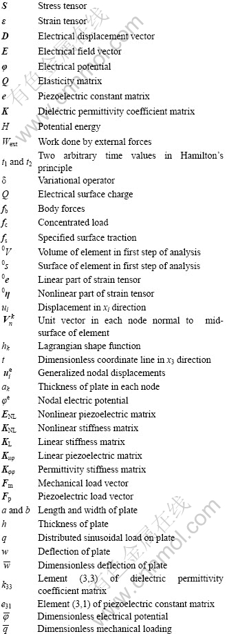
Nomenclature
References
[1] LIEW K M, HE X Q, NG T Y, SIVASHANKER S. Active control of FGM plates subjected to a temperature gradient: Modeling via finite element method based on FSDT [J]. Int J Numer Meth Eng, 2001, 52: 1253-1271.
[2] TAKAGI K, LI J F, YOKOYAMA S, WATANABE R. Fabrication and evaluation of PZT/Pt piezoelectric composites and functionally graded actuators [J]. J Eur Ceram Soc, 2003, 23: 1577-1583.
[3] KOOGL M, BUCALEM M L. A family of piezoelectric MITC plate elements [J]. Computers and Structures, 2005, 83: 1277-1297.
[4] KOOGL M, BUCALEM M L. Analysis of smart laminates using piezoelectric MITC plate and shell elements [J]. Computers and Structures, 2005, 83: 1153�C1163.
[5] LU P, LEE H P, LU C. Exact solutions for simply supported functionally graded piezoelectric laminates by Stroh-like formalism [J]. Composite Structures, 2006, 72: 352-363.
[6] VARELIS D, SARAVANOS D A. Coupled mechanics and finite element for non-linear laminated piezoelectric shallow shells undergoing large displacements and rotations [J]. Int J Numer Meth Engng, 2006, 66: 1211-1233.
[7] BUTZ A, KLINKEL S, WAGNER W. A geometrically and materially non-linear piezoelectric three-dimensional-beam finite element formulation including warping effects [J]. Int J Numer Meth Engng, 2008, 76: 601-635.
[8] VARELIS D, SARAVANOS D A. Non-linear coupled multi-field mechanics and finite element for active multi-stable thermal piezoelectric shells [J]. Int J Numer Meth Engng, 2008, 66: 1211-1233.
[9] BEHJAT B, SALEHI M, SADIGHI M, ARMIN A, ABBASI M. Static, dynamic and free vibration analysis of functionally graded piezoelectric panels using finite element method [J]. J of Intelligent Material Systems and Structures, 2009, 20: 1635-1646.
[10] BEHJAT B, SALEHI M, ARMIN A, SADIGHI M, ABBASI M. Static and dynamic analysis of functionally graded piezoelectric plates under mechanical and electrical loading [J]. Scientia Iranica, 2011, 18: 986-994.
[11] TANVEER M, SING A V. Nonlinear forced vibrations of laminated piezoelectric plates [J]. Journal of Vibration and Acoustics, 2010, 132: 1-13.
[12] THINH T, NGOC L K. Static behavior and vibration control of piezoelectric cantilever composite plates and comparison with experiments [J]. Computational Materials Science, 2010, 49: 276-280.
[13] JIASHI Y. An introduction to the theory of piezoelectricity [M]. USA: Springer Science, 2005.
[14] BATHE K J. Finite element procedures [M]. New Jersey: Prentic-Hall, 1996.
[15] BATHE K J, BOLOURCHI S. A geometric and material nonlinear plate and shell element [J]. Computers and Structures, 1980, 11: 23-48.
[16] ZHAO X. LIEW K M. Geometrically nonlinear analysis of functionally graded plates using the element-free kp-Ritz method [J]. Comput Methods Appl Mech Engrg, 2009, 198: 2796-2811.
(Edited by YANG Bing)
Received date: 2011-07-27; Accepted date: 2011-10-27
Corresponding author: B. Behjat; Tel: +98-411-3392484; Fax: +98-411-3354153; E-mail: Bashir.behjat@tabrizu.ac.ir
Abstract: Nonlinear static analysis of piezoelectric plates has been carried out using nonlinear finite element method considering electro-mechanical coupling. The geometrical nonlinearity has been taken into account and electric potential is assumed to be quadratic across the plate thickness. The governing equations are obtained using potential energy and Hamilton��s principle that includes elastic and piezoelectric effects. The finite element model is derived based on constitutive equation of piezoelectric material accounting for coupling between elasticity and electric effect using higher order plate elements. Results are presented for piezoelectric plate under different mechanical boundary conditions. Numerical results for the plate are given in dimensionless graphical forms. Effects of boundary conditions on linear and nonlinear response of the plate are also studied. The numerical results obtained by the present model are in good agreement with the available solutions reported in the literature.
