
Trans. Nonferrous Met. Soc. China 30(2020) 992-1004
Microstructure and grain boundary engineering of a novel Fe-Cr-Ni alloy weldment made with self-developed composition-matched weld filler metal
Yu ZHANG1,2, Hong-yang JING1,2, Lian-yong XU1,3, Yong-dian HAN1,2, Lei ZHAO1,2, Hai-zhou LI1,2, Zheng-xin TANG1,2, Tian-wang TONG4
1. School of Materials Science and Engineering, Tianjin University, Tianjin 300350, China;
2. Tianjin Key Laboratory of Advanced Joining Technology, Tianjin 300350, China;
3. State Key Laboratory of Advanced Welding and Joining, Harbin Institute of Technology, Harbin 150001, China;
4. Kunshan Gintune Welding Co., Ltd., Jiangsu 215312, China
Received 1 February 2019; accepted 27 March 2020
Abstract:
The microstructure, texture, and yield strength of an advanced heat-resistant alloy weldment made with composition-matched weld filler were investigated. Scanning electron microscopy, energy dispersive spectroscopy, and electron backscatter diffraction were used to characterize the microstructural and textural changes. Various grain boundary engineering (GBE) processes were performed on the weldment. The yield strengths of the weldment at 973 K were obtained before and after GBE processing, and were mostly consistent with the theoretically predicted values. The coincident-site lattices, misorientation, and recrystallization of the weld metal after GBE were analyzed, and the results indicate that the increase in dislocation density and the improvement in special grain boundaries in the weld metal are the main reasons for the yield strength elevation of the weldment after GBE. The variation in elongation after high-temperature tests has the same tendency as that in the impact toughness with different GBE parameters, which is related to the coarsening behavior of carbides.
Key words:
grain boundary engineering; advanced Fe-Cr-Ni alloy; weld metal; yield strength;
1 Introduction
Sanicro 25 is a promising super-/re-heater candidate for use in advanced 700 ��C ultra- supercritical (USC) power plants and has received considerable attention due to its exceptional high-temperature performance and outstanding resistance to steam oxidation and hot corrosion in hostile environment [1-3]. In addition, welding is recognized as an ineluctable process in the assembly of USC boiler components. Alloy 617 mod and Sanicro 53 are temporarily recommended as the most compatible welding fillers to join Sanicro 25 tubes. However, utilizing nickel-base consumables increases costs when generation plants are constructed. Moreover, the elemental redistribution and microstructural heterogeneity around the fusion interfaces tend to produce adverse effects on dissimilar weld joints. Developing a chemical composition-matched welding filler metal with lower Ni content is thus imperative for the more extensive dissemination and deployment of Sanicro 25. In our previous research [4], a metal- cored welding wire was manufactured for adjusting chemical elements easily. The corresponding all-weld-metal deposits were prepared through shielded metal arc welding to determine the mechanical properties, which presented superior performance over Sanicro 25 at both room and high temperatures.
Control of grain boundary has been one of the most important topics of materials science and engineering associated with grain boundaries since the 1950s. Grain boundary engineering (GBE), which was first proposed in 1984 [5], has been extensively applied by many research groups to improve the bulk properties in structural and functional polycrystalline materials [6-8]. Essentially, GBE manipulates the grain boundaries in microstructures that have a significant fraction of lower sigma coincident-site lattice (CSL) boundaries. The important features of GBE are the frequency of such boundaries, their distribution, and the ability to replace the network of random high-angle grain boundaries [9].
In this work, Sanicro 25 weldments were prepared by gas tungsten arc welding (GTAW) with a self-developed solid wire dedicated to Sanicro 25. The weldment specimens were then subjected to different GBE processes. The microstructures of the welded joint before and after GBE were studied in detail to confirm the strengthening mechanism. Tensile tests of the welded joint before and after GBE were conducted at 973 K and the yield strength and ultimate tensile strength were theoretically calculated. Moreover, the fracture surfaces of the ruptured tensile test specimens were examined and the related failure modes were analyzed.
2 Experimental
2.1 Materials
The as-received Sanicro 25 alloy used in the present investigation was cold-pilgered and solution-treated (1417-1523 K) in a seamless tube with size of 53.8 mm �� 8.9 mm. The ASME standard chemical compositions of Sanicro 25 are listed in Table 1. Based on the alloying system modified from the aforementioned study [4], solid metal wires (named GTSA25) were produced with a diameter of 2.4 mm in an indigenous welding consumable enterprise. The chemical compositions of the GTSA25 are listed in Table 1 as well. The manufacturing processes of solid metal wires can be described as follows. A vacuum induction melting furnace was used to prepare metal ingots. A new ingot was prepared in the cooled crucible by directional solidification from bottom to top while avoiding macro and micro segregation. The wire steel was made from billet (forging and rolling billet from ingot). After the billet passed through the heating furnace, the roughing mill, intermediate rolling mill, finishing mill, reducing, sizing mill, and laying head, it became a wire rod (in a diameter of 8-9 mm). After cold drawing, the wire rod was made as a welding wire. GTAW with 100% argon shielding was applied to producing the welded joints (with argon shielding on the back of the weld metal (WM)). The interrelated welding specifications are listed in Table 2. The measured chemical compositions of the base metal (BM) and WM of the joint are listed in Table 1. Photographs of the weldments are provided in Fig. 1.
2.2 GBE and experimental procedures
Table 1 Chemical compositions of Sanicro 25 (S25), welding wire (GTSA25) and weldment (wt.%)

Table 2 Welding specifications for Sanicro 25 welded joints


Fig. 1 Photograph and schematic representation of weldments
The high-temperature tensile specimens were taken parallel to the axial direction of the as-welded Sanicro 25 tube, as shown in Fig. 1. These specimens then received GBE heat treatment in an electric furnace (Tianjin Zhonghuan SX-G03163) in air at 973 K for different holding times (listed in Table 3). The specimens were hydrocooled immediately after the holding time was completed. A high-temperature tensile test was conducted using an electronic creep testing machine (CRIMS RDL50) with a loading rate of 0.1 mm/min. For the high-temperature tensile experiments, the specimen was attached to three K-type thermocouples to monitor the test temperature. Extensometers were used to measure the gauge length displacement of each specimen in the tensile tests. The gauge length for each specimen before and after testing was examined to obtain the elongation value. Impact toughness tests were conducted in the WM center at room temperature. The dimensions of the impact specimens were 5 mm �� 10 mm �� 55 mm with a 2 mm V-shaped notch at the specimen center. Specimens with notches in each zone were tested in quadruplicate. In this study, high-temperature tensile tests and Charpy impact tests were conducted according to standards GB/T 4338��2006, and GB/T 229��2007, respectively.
Table 3 Grain boundary serrations parameters for Sanicro 25 weldment

2.3 Material characterization
An optical microscope (OM, Olympus GX51) and field-emission scanning electron microscope (SEM, ZEISS GeminiSEM 500) with energy dispersive spectroscope (EDS, Oxford Instruments) were used for microstructural characterization. Samples for OM and SEM microstructure examination were embedded and ground, and then polished using diamond pastes. These were finally etched with a solution of HCL (20 mL), ethanol (20 mL), and CuSO4 (5 g). Grain boundary transformation was measured by electron backscatter diffraction (EBSD, Oxford Instruments). Channel 5 software was used to analyze the EBSD results and display the final data. The EBSD samples were ground and electrolytically polished in an alcohol solution of 4% perchloric acid. JmatPro software can emulate a wide variety of material properties, including stable/quasistable phase equilibria and solidification behavior. In this study, by importing the measured chemical composition of the WM into the JmatPro software (version 7.0), the mass fractions of various stable phases ranging from 200 to 1800 K could be calculated.
3 Results and discussion
3.1 Thermodynamics simulation
In order to choose optimal GBE parameters, previous relevant studies were carefully examined [5,6,8,10,11]. Then, 973 and 1033 K were selected as candidates for the GBE temperature. The weldment after heat treating at 1033 K, however, showed a decrease in mechanical properties (particularly the ultimate tensile strength). Therefore, this study was concentrated on the mechanical properties and microstructures of the weldment before and after treatment at 973 K. Equilibrium phase proportions ranging from 200 to 1600 K of the WM are shown in Fig. 2. MX (M is normally a carbide- or nitride-forming transition metallic element such as Ti or V), M23C6, Z phase, Laves and Sigma phases may exist in the room-temperature microstructure of the WM. A phase structure with specific amounts of carbides and nitrides is beneficial to increasing the deformation resistance of metals, a finding similar to those described in the aforementioned studies.

Fig. 2 Stable phase proportions of weld metal ranging from 200 to 1600 K
3.2 Microstructures of weldment before and after GBE
3.2.1 As-welded microstructures
Metallographs of the welded joint are shown in Fig. 3, where the four welding layers are enveloped. The heat-affected zones were nearly invisible. This was caused by the small welding current that restricts the grain growth of the BM in a solution-treated condition [12]. SEM observations of the BM are shown in Fig. 4. The BM showed a typical austenitic matrix with primary particles and a twinned microstructure. However, the EDX results demonstrate that a microscale Nb-rich phase is observed on both the rolling (R) and transverse (T) planes, whereas a Ti-rich phase with a zonal arrangement (indicated by yellow arrows) can only be found on the T plane. The precipitation-induced anisotropy can be explained by the introduction of coherent, directional precipitates into the matrix on different planes [13].
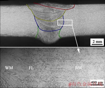
Fig. 3 Metallographs of welded joint
Figure 5 shows metallurgical and SEM images of the WM. Two primary types of precipitates were revealed in the WM microstructure: carbide (M23C6), which was found in the weld metal grain boundary, and Nb-rich Z phase, which was mainly intragranular. M23C6 is a carbide that tends to select preferential planes with the lowest interfacial energy and is responsible for the triangular carbide morphology at random boundaries. Carbide nucleation relies on the concentration of carbon and chromium, which do not experience significant coarsening during welding [14,15]. Intensive nitrogen segregation overlapping with chromium at the coarsened G-phase (Nb(C,N) or MX phase) center may cause Z-phase precipitation of Nb(C,N) during aging as well as consumption of Nb(C,N) during subsequent growth [16].
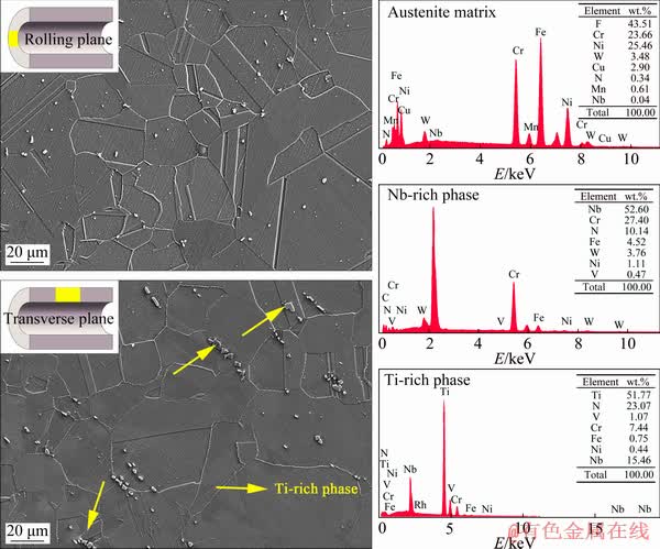
Fig. 4 SEM observations of base metal

Fig. 5 Metallurgical and SEM micrographs of weld metal
The fusion boundaries were found to be extremely vague, according to Fig. 6. This was caused by the close chemical compositions of BM and WM. During welding, the grains in the BM adjacent to the fusion zone partially melt and subsequently solidify when connected to the WM grains toward the weld center. Figure 7(a) displays the element distribution across the fusion boundary, revealing that elemental iron was slightly reduced in the WM due to the rejection of Fe into the BM by the solid WM during the initial stage of transient solidification [4]. Moreover, regions subjected to more than one weld pass as shown in Fig. 7(b) have an elemental segregation tendency similar to that in Fig. 7(a). Nevertheless, the element dilution and remigration during the remelting and resolidification processes induced by heating of the subsequent weld pass were not observed. This means that a smooth element transition occurred around the fusion boundary of this type of welded joint, thus producing a certain homogeneity in microstructures between the BM and WM.
3.2.2 GBE microstructures in weld metals

Fig. 6 SEM observation of fusion boundary
Because the grain boundary characteristics of the BM underwent very little change after GBE as compared to those of the WM, we considered only the WM. The CSL of the WM in the samples that underwent different GBE procedures was measured using EBSD, as shown in Fig. 8(a). CSL boundaries are characterized by the special values of misorientation, which enable the atoms from neighboring lattices to coincide notionally, and the reciprocal density of coinciding sites is defined as �� [17]. GBE refers mainly to the formation of multiple twinning structures in which only CSL boundaries present in abundance are ��3, which mostly influence special properties and a few other ��3n types. The present work regarded CSLs not larger than ��29 as special grain boundaries (also special boundaries or SBs) and in addition calculated the percentages of SBs in all CSL boundaries as well as ��3 boundaries in SBs, as shown in Fig. 8(b). It can be seen that both values increased after GBE, which is consistent with a previous study on nanocrystalline GBE [18]. The number of SBs is low prior to GBE and increases considerably after GBE. In addition, ��3 content remains to be zero in WMs for GBE0 and GBE1 but gradually increases to a high level following GBE2 and GBE3. Previous research has assumed that the increase in SBs was mainly due to an increase in the ��3 grain boundaries [19]. With respect to GBE, the critical case in which annealing twinning adds special boundaries to the microstructure when an annealing twin is nucleated from or meets a ��3n boundary with n>1. Annealing twinning is considered to form for one of two reasons: (1) to diminish the overall interfacial energy when the energy of the boundaries between neighbors of a grain and its twin is less than that of the boundaries between the neighbors and the grain itself, or (2) to reorientate grain boundaries to facilitate dislocation absorption and mobility during recrystallization. The role of twinning in GBE is necessary for the appropriate enhancement of the microstructure and properties: first to retain strain, then to generate noncoherent ��3 boundaries (and other ��special�� boundaries), and finally to break up the random boundary network.

Fig. 7 Solute distributions across fusion boundary of microstructure subjected to one weld pass (a) and microstructure subjected to more than one weld pass (b)

Fig. 8 CSL maps of weld metals (a) and SBs fractions (b)
To evaluate the variation in local orientation, kernel average misorientation (KAM) maps for the weldments before and after GBE are shown in Fig. 9. The KAM maps can be interpreted as the mean misorientation of a point with respect to its nearest adjacent points on the map. Based on the KAM results, the geometrically necessary dislocations (GNDs) that represent the local crystal orientation in a given region were measured for each sample. GND density can be calculated as
��GND=2��/��b (1)
where ��GND is the GND density at the point of interest, �� is the local misorientation angle, �� is the unit length (400 nm) of the point, and b is the absolute value of Burger vector (0.248 nm for an FCC structure). As shown in Fig. 9, an increasing GND density is observed in the samples as the GBE holding time increases. According to a study on low-stacking-fault energy materials [20], a higher GND density implies that extensive twinning accumulates strain energy in the material, causing subsequent selective grain-boundary migration.

Fig. 9 KAM maps of weld metals before and after GBE
Previous work [21] showed that the GBE constituted a recrystallization process that involves the formation of large grain clusters with many inner-connected ��3n- type triple junctions. The recrystallization maps are shown in Fig. 10, where recrystallized and non-recrystallized regions are separated by random grain boundaries. As the annealing time increased from 15 to 60 min, the fraction of recrystallization also increased, which was consistent with the variation trend of ��3. During recrystallization, the grain clusters began to grow from a single recrystallized nucleus, and were then formed through generation of a series of ��3 annealing twin boundaries. Simultaneously, ��3n grain boundaries occurred when different generation twinned grains met. Forming annealing twins for FCC structures with low stacking fault energy during a period of newly formed grain growth is easy. Thus, new annealing twins were iteratively produced on the moving grain boundary during recrystallization, leading to the inter- connecting ��3n-type grain boundaries.

Fig. 10 Recrystallization maps of weld metals before and after GBE
3.3 High-temperature tensile properties
Tensile test results at 973 K are displayed in Fig. 11. The high-temperature strength variations in the weldment before and after GBE are shown in Fig. 12, where the increase rate of the yield strength against that of the weldment that did not undergo GBE processing is present.

Fig. 11 High-temperature engineering tensile curves at 973 K
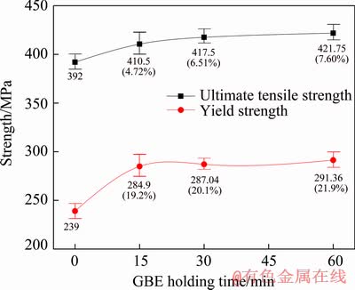
Fig. 12 High-temperature tensile test results
3.3.1 Theoretical prediction of yield strength
To explain the yield strength variations of the weldments before and after GBE, a proof stress prediction model [22] was used by measuring the microstructural parameters. The 0.2% proof stress (��y) was computed by aggregating the root-mean- square of components ��A and ��B, which are strengthening factors associated with different types of obstacles. ��A is the dislocation strengthening (��d), and ��B includes all other components of the yield strength. The contribution of dislocations to strengthening (��d) can be calculated by
��d=��Gb��0.5 (2)
where G is the shear modulus (55.69 GPa at 973 K), b=0.248 nm, and �� is the total dislocation density obtained from EBSD. In the equation, �� is a constant, and 0.38 was adopted in the present modeling according to the literature [22]. Figure 13 presents the variations in GND density and dislocation strengthening, which showed a similar tendency with increasing the holding time. The theoretically calculated creep threshold stress (��th) of Sanicro 25 at 973 K reported in Ref. [1] was 113.37 MPa. Because the main strengthening precipitate of the weldment is a nano-sized Cu-rich phase, the precipitate strengthening (��p) could be regarded as ��th. The strengthening from substitutional elements in the solid solution after precipitation was considered here. Based on a systematic experimental work by REITER and HIBBARD [23] that confirmed the strengthening effects of substitutional alloying elements in a BCC iron matrix, the strength ��ss derived from the substitutional alloying elements can be expressed simply as
��ss=0.00689kXm (3)
where ��ss is the strength (MPa), k is the strengthening coefficient, X is the equilibrium content of substitutional elements (at.%), and m=0.75 for all elements investigated. A higher value of k implies a greater substitutional element strengthening effect. The value of ��ss was approximately 50 MPa for GBE0 and 100 MPa for GBE1, GBE2 and GBE3, which was obtained by determining the content of substitutional elements through EDS [24]. Furthermore, the work hardening effect during tensile testing should be considered as contributing to ��y. A value of ��wh (=40 MPa) was adopted in this study to be the work hardening term based on the assumption that matrix microstructures respond similarly to external stress, even though the element segregations of the four materials were different. To summarize the aforementioned results, we can solve ��B=��p+��ss+��wh. The root mean squares of components ��A and ��B ( ) are plotted in Fig. 14 and compared to the experimental values. The theoretical prediction and experimental values were very close, strongly demonstrating the effects of each component.

Fig. 13 Variations of GND density and dislocation strengthening
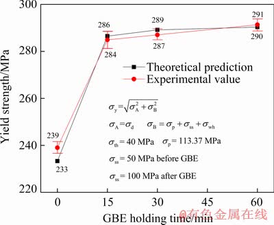
Fig. 14 Yield strength of weldment at 973 K
3.3.2 Relationship between microstructure and tensile property
Three reasons may explain the enhancement of the yield strength at 973 K for the WMs that underwent the GBE processes. First, GBE heat treatment helps to generate large CSL boundaries (especially twinning boundaries) in the WM, which facilitates the retention of strain and increases the strength. Subsequently, an increased GND density was observed in the GBE samples as compared to the original as-welded sample. The dislocation density is well-known as strongly influencing the yield strength. Eventually, nanosized precipitates such as Cu-rich and NbN phases may form during the GBE process [25], but little time remains for the nanoscale phases to coarsen due to hydrocooling. The precipitation strengthening mechanism thus plays a role in improving the yield strength at 973 K.
3.3.3 Fracture surface analyses
The fracture surfaces of the ruptured specimens after high-temperature tests are shown in Fig. 15. The rupture position was in the WM for all tensile tests. As Fig. 15(a) shows, the weldment without GBE processing ruptured in a typical intergranular manner, which is a common phenomenon in heat-resistant materials [26]. The fracture surfaces of the ruptured specimens of GBE1 and GBE2 showed dense and less-dense distributions of dimples, as shown in Fig. 15(b) and (c), respectively. However, the ruptured specimen of GBE3 exhibited a mix fracture mode with dimples and intergranular features. Based on our previous studies [1,27], the fracture mode is strongly dependent on the microstructure evolution at a high temperature. The intracrystalline precipitates in the WM after GBE processing for 15 min were very small, and the ductility of the weldment increased significantly. However, the precipitation coarsened after a longer GBE holding time (30 min). These coarsened particles thus produced larger but sparse dimples, which led to reduced ductility. When the GBE holding time was increased to 60 min, the fracture surface had a somewhat intergranular characteristic, which may be caused by the coarse carbides that formed along the grain boundary. As plotted in Fig. 16, the variations between the elongation and impact toughness versus the GBE holding time showed a tendency that was mostly consistent with the fracture surface analyses.
4 Conclusions
(1) The BM displayed an anisotropic distribution of a Ti-rich phase. A Z phase and carbides were found in the WM. The fusion boundary exhibited a homogeneous microstructure, which may have contributed to the enhanced mechanical properties of the weldment.
(2) The increase in dislocation and improved special grain boundaries in the WM were regarded as the main reasons for the yield strength elevation of the weldment after GBE, which was confirmed by theoretical calculation.
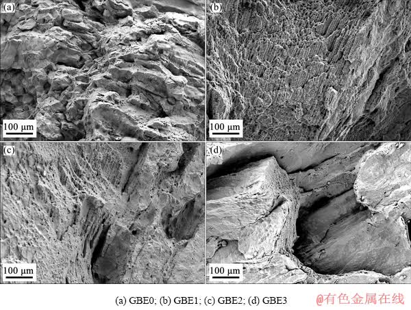
Fig. 15 Typical fractographs after high-temperature tensile tests

Fig. 16 Elongation after high-temperature tensile tests and impact toughness
(3) The weldment after GBE1 showed better ductility because insufficient time was allowed for the precipitates to coarsen. Holding time of 15 min could be selected as an optimal GBE parameter when considering comprehensive performance.
References
[1] ZHANG Y, JING H Y, XU L Y, ZHAO L, HAN Y D, ZHAO Y X. High-temperature deformation and fracture mechanisms of an advanced heat resistant Fe-Cr-Ni alloy [J]. Materials Science and Engineering A, 2017, 686: 102-112.
[2] KORZHAVYI P A, SANDSTROM R. First-principles evaluation of the effect of alloying elements on the lattice parameter of a 23Cr25NiWCuCo austenitic stainless steel to model solid solution hardening contribution to the creep strength [J]. Materials Science and Engineering A, 2015, 626: 213-219.
[3] RUTKOWSKI B, GIL A, CZYRSKA-FILEMONOWICZ A. Microstructure and chemical composition of the oxide scale formed on the Sanicro 25 steel tubes after fireside corrosion [J]. Corrosion Science, 2016, 102: 373-383.
[4] ZHANG Y, JING H Y, XU L Y, HAN Y D, ZHAO L, WANG D F, XIAO B. Design and performance of weld filler metal to match an advanced heat-resistant Fe-Cr-Ni alloy [J]. Materials Science and Engineering A, 2018, 721: 103-116.
[5] KOBAYASHI S, KOBAYASHI R, WATANABE T. Control of grain boundary connectivity based on fractal analysis for improvement of intergranular corrosion resistance in SUS316L austenitic stainless steel [J]. Acta Materialia, 2016, 102: 397-405.
[6] SINGH G, HONG S, OH-ISHI K, HONO K, FLEURY E, RAMAMURTY U. Enhancing the high temperature plasticity of a Cu-containing austenitic stainless steel through grain boundary strengthening [J]. Materials Science and Engineering A, 2014, 602: 77-88.
[7] GIBSON M A, SCHUH C A. Segregation-induced changes in grain boundary cohesion and embrittlement in binary alloys [J]. Acta Materialia, 2015, 95: 145-155.
[8] SINHA S, KIM D, FLEURY E, SUWAS S. Effect of grain boundary engineering on the microstructure and mechanical properties of copper containing austenitic stainless steel [J]. Materials Science and Engineering A, 2015, 626: 175-185.
[9] RAABE D, HERBIG M, SANDLOBES S, LI Y, TYTKO D, KUZMINA M, PONGE D, CHOI P P. Grain boundary segregation engineering in metallic alloys: A pathway to the design of interfaces [J]. Current Opinion in Solid State and Materials Science, 2014, 18: 253-261.
[10] GHORBANI S, GHASEMI R, EBRAHIMI- KAHRIZSANGI R, HOJJATI-NAJAFABADI A. Effect of post weld heat treatment (PWHT) on the microstructure, mechanical properties, and corrosion resistance of dissimilar stainless steels [J]. Materials Science and Engineering A, 2017, 688: 470-479.
[11] JIANG L, HU R, KOU H C, LI J S, BAI G H, FU H Z. The effect of M23C6 carbides on the formation of grain boundary serrations in a wrought Ni-based superalloy [J]. Materials Science and Engineering A, 2012, 536: 37-44.
[12] ZHANG Y, JING H Y, XU L Y, HAN Y D, ZHAO L, XIAO B. Microstructure and mechanical performance of welded joint between a novel heat-resistant steel and Inconel 617 weld metal [J]. Materials Characterization, 2018, 139: 279-292.
[13] MISHRA S, KULKARNI K, GURAO N P. Effect of crystallographic texture on precipitation induced anisotropy in an aluminium magnesium silicon alloy [J]. Materials and Design, 2015, 87: 507-519.
[14] HONG H U, RHO B S, NAM S W. Correlation of the M23C6 precipitation morphology with grain boundary characteristics in austenitic stainless steel [J]. Materials Science and Engineering A, 2001, 318: 285-292.
[15] GUSTAFSON S, H TTESTRAND M. Coarsening of precipitates in an advanced creep resistant 9% chromium steel��Quantitative microscopy and simulations [J]. Materials Science and Engineering A, 2002, 333: 279-286.
[16] DEWAR M P, GERLICH A P. Correlation between experimental and calculated phase fractions in aged 20Cr32Ni1Nb austenitic stainless steels containing nitrogen [J]. Metallurgical and Materials Transactions A, 2013, 44: 627-639.
[17] RANDLE V. Twinning-related grain boundary engineering [J]. Acta Materialia, 2004, 52: 4067-4081.
[18] BOBER D B, KUMAR M, RUPERT T J. Nanocrystalline grain boundary engineering: Increasing ��3 boundary fraction in pure Ni with thermomechanical treatments [J]. Acta Materialia, 2015, 86: 43-54.
[19] AHMEDABADI P M, KAIN V, DANGI B K, SAMAJDAR I. Role of grain boundary nature and residual strain in controlling sensitisation of type 304 stainless steel [J]. Corrosion Science, 2013, 66: 242-255.
[20] RANDLE V. Mechanism of twinning-induced grain boundary engineering in low stacking-fault energy materials [J]. Acta Materialia, 1999, 47: 4187-4196.
[21] BAI Q, ZHAO Q, XIA S, WANG B S, ZHOU B X, SU C. Evolution of grain boundary character distributions in alloy 825 tubes during high temperature annealing: Is grain boundary engineering achieved through recrystallization or grain growth? [J]. Materials Characterization, 2017, 123: 178-188.
[22] LI Q. Modeling the microstructure�Cmechanical property relationship for a 12Cr-2W-V-Mo-Ni power plant steel [J]. Materials Science and Engineering A, 2003, 361: 385-391.
[23] REITER S F, HIBBARD W R. High temperature properties of iron-rich Fe-Mo alloys [J]. Journal of Metals, 1955, 7: 655-663.
[24] LESLIE W C. Iron and its dilute substitutional solid solutions [J]. Metallurgical and Materials Transactions B, 1972, 3: 5-26.
[25] GUO Y, LI T J, WANG C X, HOU S F, WANG B H. Microstructure and phase precipitate behavior of Inconel 740H during aging [J]. Transactions of Nonferrous Metals Society of China, 2016, 26: 1598-1606.
[26] ZHANG Y, JING H Y, XU L Y, HAN Y D, ZHAO L, XIE X S, ZHU Q H. Creep behavior and life assessment of a novel heat-resistant austenite steel and its weldment [J]. Acta Metallurgica Sinica (English Letters), 2019, 32: 638-650.
[27] ZHANG Y, JING H Y, XU L Y, ZHAO L, HAN Y D, LIANG J. Microstructure and texture study on an advanced heat-resistant alloy during creep [J]. Materials Characterization, 2017, 130: 156-172.
�����з������Ʊ�������Fe-Cr-Ni�Ͻӽ�ͷ������֯�뾧�繤��
�� ��1,2��������1, 2��������1,3��������1,2���� ��1,2�����1,2�������{1,2��ͯ����4
1. ����ѧ ���Ͽ�ѧ�빤��ѧԺ����� 300350��
2. ������ִ����Ӽ����ص�ʵ���ң���� 300350��
3. ��������ҵ��ѧ �Ƚ����������ӹ����ص�ʵ���ң������� 150001��
4. ��ɽ��Ⱥ���ĿƼ�����˾������215312
ժ Ҫ���о������������ijɷ�ƥ�亸���Ʊ����Ƚ����ȺϽӽ�ͷ������֯��֯��������ǿ�ȡ�����ɨ��羵�������Ǻ͵��ӱ�ɢ�似�����б�������Ժ�����չ��ͬ�����ľ��繤�̣����Ծ������繤��ǰ���� 973 K�µ�����ǿ�ȣ���ʵ������Ԥ��ֵ�����ͨ���۲쾧�繤�̴������������غ�λ�õ�����ȡ�����ٽᾧ������������λ���ܶȺ͡����⾧�硱�����������Ǿ��繤�̴���������ǿ����������Ҫԭ��������Ϻ��쳤�ʺͳ���������Ų�ͬ���繤�̴��������ı仯�������������̼����Ĵֻ���Ϊ�йء�
�ؼ��ʣ����繤�̣��Ƚ�Fe-Cr-Ni�Ͻ𣻺������������ǿ��
(Edited by Bing YANG)
Foundation item: Project (51475326) supported by the National Natural Science Foundation of China; Project (BHSF2017-22) supported by the Demonstration Program of National Marine Economic Innovation of Tianjin City, China
Corresponding author: Lian-yong XU; E-mail: xulianyong@tju.edu.cn
DOI: 10.1016/S1003-6326(20)65271-2
Abstract: The microstructure, texture, and yield strength of an advanced heat-resistant alloy weldment made with composition-matched weld filler were investigated. Scanning electron microscopy, energy dispersive spectroscopy, and electron backscatter diffraction were used to characterize the microstructural and textural changes. Various grain boundary engineering (GBE) processes were performed on the weldment. The yield strengths of the weldment at 973 K were obtained before and after GBE processing, and were mostly consistent with the theoretically predicted values. The coincident-site lattices, misorientation, and recrystallization of the weld metal after GBE were analyzed, and the results indicate that the increase in dislocation density and the improvement in special grain boundaries in the weld metal are the main reasons for the yield strength elevation of the weldment after GBE. The variation in elongation after high-temperature tests has the same tendency as that in the impact toughness with different GBE parameters, which is related to the coarsening behavior of carbides.
