
J. Cent. South Univ. (2012) 19: 374-379
DOI: 10.1007/s11771-012-1014-5![]()
A new dimmer for alternating-current directly driven light-emitting-diode lamp
KIM Jong-hyun, RYU Myung-hyo, YOON Hyok-min, SONG Eui-ho
School of Mechatronics, Changwon National University, Changwon 641-773, Korea
? Central South University Press and Springer-Verlag Berlin Heidelberg 2012
Abstract:
A new dimmer using a mental-oxide-semiconductor field-effect transistor (MOSFET) for alternating-current (AC) directly driven light-emitting-diode (LED) lamp was presented. The control method of proposed dimmer is pulse width control (PWM) method. Compared with the conventional phase-controlled dimmer, the proposed PWM dimmer can produce sine wave and did not cause harmonics problem. Furthermore, the proposed control method did not amplify the light flicker due to the independence of input voltage. Therefore, the PWM dimmer can be used as the dimmer of the AC LED lamp instead of the conventional phase- controlled dimmer. The experimental result shows that the proposed PWM dimmer has good performances.
Key words:
1 Introduction
Nowadays, energy saving, carbon reduction and environmental protection recently have become a common consensus of every country. To comply with these energy policies, lower power consumption, higher lumen efficiency, longer lifespan and lower pollution are the most important demands for new light sources. Alternating-current (AC) directly driven light-emitting- diode (LED) lamp is one of products which meets these demands. Alternating-current directly driven LED lamp is the light source that operates directly from a sinusoidal AC voltage source (VAC), typically the utility line voltage (e.g. 120 V in US, 100 V in Japan and 220 V in Europe) without a converter. Because of its simplicity, AC LED lamp has tremendous potential to become the dominant type of lighting in many applications. This makes it suitable to many residential and commercial lighting applications where the main source of available power is AC [1-5].
The dimmer is a power electronic device for lighting control used in various applications including industrial and residential lighting control. The use of dimmers brings many advantages to consumers. One advantage is that the use of dimmers is very convenient. Another advantage is energy conservation. Up to now, phase-controlled dimmers using a triac (or two thyristors) have been the main technique for lighting control. And their circuits had been developed both with forward and reverse phase-controlled approaches [6].
In the forward phase-controlled dimmers, the triac was triggered into conduction at some points during the AC half-cycle and continued to conduct until it self-commutated at the end of the half-cycle [7-9]. These dimmers produced audible noises in lamps due to the sharp turn-on waveform of current. So, a large bulky filter-inductor was needed to be placed in series with the load to reduce the rate of change of current through the lamp in the forward phase-controlled dimmer. But the price to be paid for this was the addition of bulky inductors, introducing both resistive and reactive power losses. An alternate method to avoid using the bulky inductor was the reverse phase-controlled approaches [10-11]. In the reverse phase-controlled dimmers, the triac was triggered into conduction immediately after the zero crossing of line voltage and then commutated off at some points during the AC half-cycle. The bulky filter- inductor could be replaced by a less expensive capacitor in parallel with the power switches and the rate of change of current through the load after turn-off would be reduced [10, 12-13].
To solve the harmonics problem, the pulse width control (PWM) dimmer using a mental-oxide- semiconductor field-effect transistor (MOSFET) for AC directly driven LED lamp was proposed in this work. Because the control of proposed PWM dimmer was independent of the input voltage, it did not amplify the light flicker. The proposed PWM dimmer consisted of only two active switches and an electro magnetic interference (EMI) filter. Because two active switches were configured with common source and gate, they can be easily driven by one of PWM signal. An EMI filter is for the elimination of high frequency component. So, it can be small and light. The volume of two active switches and an EMI filter are so small that the proposed dimmer can be used as the dimmer of the AC LED lamp instead of phase-controlled dimmer.
From harmonics and voltage flicker point of view, a 100 W proto-type PWM dimmer was implemented and compared with phase-controlled dimmer. The proposed PWM dimmer for AC LED lamp can improve harmonics and is less sensitive voltage flicker. The validity of the proposed strategy was verified by experiment in details.
2 Phase-controlled dimmer
Figure 1 shows the basic schematic diagram of the previous forward phase-controlled dimmer and typical waveform. The triac Q1 was triggered into conduction at the desired phase angle (��) and off at the zero crossing of the line voltage to transfer partial power from line to the lamp.
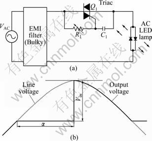
Fig. 1 Typical phase-controlled dimmer: (a) Basic circuit; (b) Typical waveform
The output voltage function (Vout) of the triggering phase angle is given by
![]() (1)
(1)
where Vout and Vin are root mean square (RMS) value of the output voltage of dimmer and the line voltage, respectively [14]. VF is threshold voltage of AC LED.
The power factor (FP) can be expressed as
![]() (2)
(2)
Under the dimming condition, the output waveform is noticeably deformed and has undesirable harmonics. If the triggering phase angle �� is closed to ��, the power factor decreases.
As the lamp current is distorted by the dimmer, harmonic currents are produced. The worst case occurs when the triac is turned on in the maximum voltage of the sinusoidal waveform. In this case, the third harmonic current is predominant. So, a large bulky filter-inductor is needed to be placed in series with the load to reduce the rate of change of current through the lamp.
The firing angle is determined by a combination of the magnitude of the line voltage and R1-C1 time delay, as shown in Fig. 1. Under the same R1-C1 time delay, the magnitude of the line voltage has an effect on the triggering phase angle. When the magnitude of the line voltage is Vin, the triggering phase angle is ��, as shown in Fig. 1(b). As the magnitude of the line voltage increases to Vin,1, the triggering phase angle decreases to (��-��1). The angle ��1 is the result affected by the magnitude of the increased line voltage Vin,1. Then, the RMS value of the output voltage is more increased, as shown in Fig. 2(a). As the magnitude of the line voltage decreases to Vin,2, the triggering phase angle increases to (��+��2). The angle ��2 is the result affected by the magnitude of the decreased line voltage Vin,2. Then, the RMS value of the output voltage is decreased, as shown in Fig. 2(b). In this way, the phase controlled-dimmer substantially amplifies the light flicker which is caused by the fluctuation of the line voltage [9].
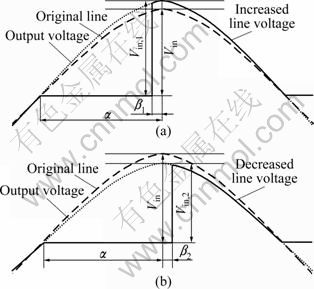
Fig. 2 Waveforms under voltage flicker: (a) Increased line voltage; (b) Decreased line voltage
3 Proposed PWM dimmer
Figure 3 shows the basic schematic diagram of proposed PWM dimmer and typical waveforms. The PWM dimmer consists of only two active switches and an EMI filter. An EMI filter is for the elimination of high frequency component. Two active switches (MOSFET Q1, Q2) are comprised with common source and gate, which turn on and off simultaneously and can be easily driven by one signal. The output voltage (Vout) of PWM dimmer is given by diode of the switches Q1 and Q2, as shown in Fig. 4(b). Because the control of PWM dimmer is independent of the input voltage, the proposed dimmer does not amplify the light flicker.
![]() (3)
(3)
where Vout is RMS value of the output voltage of dimmer; Vin is RMS value of the line voltage; D is a duty ratio; VF is threshold voltage of AC LED.
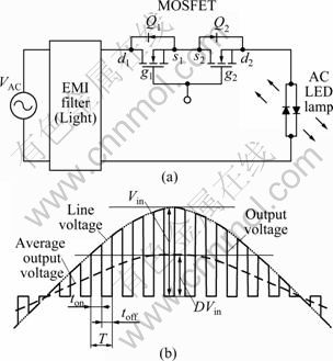
Fig. 3 Proposed PWM dimmer: (a) Basic circuit; (b) Typical waveforms
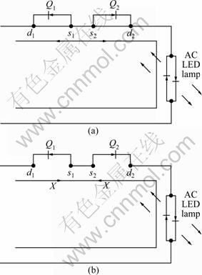
Fig. 4 Operation modes of proposed PWM dimmer: (a) Powering mode; (b) Blocking mode
Figure 4 shows two possible modes during one switching cycle. During the powering mode (ton), the switches Q1 and Q2 are turned on and the input current flows through the switches Q1 and Q2, as shown in Fig. 4(a). During this mode, the input power is transferred to the lamp. The blocking mode (toff) is complementary to the powering mode. During this mode, the switches Q1 and Q2 are turned off and the input current is blocked by the body.
4 Experimental result
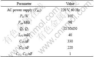
In order to verify the proposed dimmer for AC LED lamp, the PWM dimmer with EMI filter, as shown in Fig. 5, is implemented and detail parameters are listed in Table 1. Input filters (CX1, CX2 and LF1) are adapted to the PWM dimmer to filter out high frequency current. The universal power analyzer (WT3000) is used to measure the harmonics in the input current.
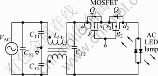
Fig. 5 Proposed PWM dimmer with EMI filter
Table 1 System paameters
Under the same input voltage of 220 V and output voltage of 195 V, comparison results of harmonic components in the input current between the phase- controlled dimmer and the proposed PWM dimmer are shown in Fig. 5 and Table 2. Figures 6 and 7 show the typical waveforms of phase-controlled dimmer and the proposed PWM dimmer under the above condition. The test results indicate that the total harmonic distortion (THD) of phase-controlled dimmer is 108% and the third harmonic current is 81.6%. On the other hand, the THD of proposed PWM dimmer is significantly reduced to 48% and the third harmonic current is also decreased to 47.3%.
Table 2 Harmonics analysis
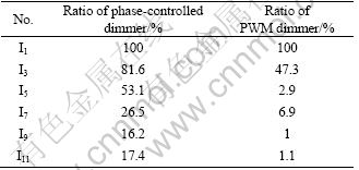
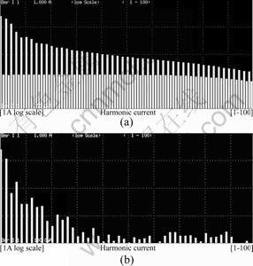
Fig. 6 Measured harmonics in input current: (a) Phase- controlled dimmer at 50 W; (b) Proposed PWM dimmer at 50 W
Figure 7(a) shows the typical waveforms of phase- controlled dimmer at firing-angle of 90��. The output voltage is 195 V and it is equal to the result of Eq. (1). Figure 7(b) shows typical waveforms of phase- controlled dimmer under the voltage flicker with lower voltage of 200 V AC power supply, and its output voltage is 165 V. The voltage flicker affects on the R-C gate circuit of triac dimmer and it delays firing-angle. Therefore, a decrease in the output voltage is larger than the input voltage. In the case of voltage flicker with higher voltage of 240 V AC power supply, the typical waveforms of phase-controlled dimmer are shown in Fig. 7(c), and the output voltage is 216 V. The voltage flicker also affects on the R-C gate circuit of triac dimmer and it advances firing-angle ahead. Namely, an increase in the output voltage is larger than the input voltage. In this case, the light flicker is amplified by the voltage flicker in the phase-controlled dimmer.
On the other hand, Fig. 8(a) shows the typical waveforms for applying the proposed PWM dimmer with duty ratio of 0.5. The output voltage is 195 V and it is equal to the result in Eq. (3). Figure 8(b) shows the expanded waveform of Fig. 8(a). The switching frequency FSW is 98 kHz and the input power is transferred to the lamp during the powering mode (ton). Figure 8(c) shows the typical waveforms of PWM dimmer under the voltage flicker with lower voltage of 200 V AC power supply, and its output voltage is 180 V. Figure 8(d) shows the typical waveforms of the PWM dimmer under the voltage flicker with higher voltage of 240 V AC power supply. The output voltage is 205 V. Because the duty ratio is independent of the input voltage, the PWM dimmer does not amplify the light flicker for the voltage flicker.
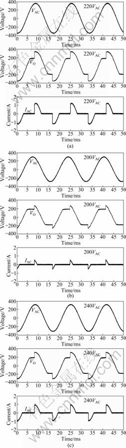
Fig. 7 Waveforms of phase-controlled dimmer with bulky inductor: (a) Typical waveforms; (b) Under voltage flicker with lower voltage of 200 V AC power supply; (c) Under voltage flicker with higher voltage of 240 V AC power supply
Figure 9 shows photographs of the phase-controlled and the PWM dimmer. Because the size of the PWM dimmer is similar to that of phase-controlled dimmer, instead of the previous phase-controlled dimmer, the PWM dimmer can be used for the residential wall dimmer models.
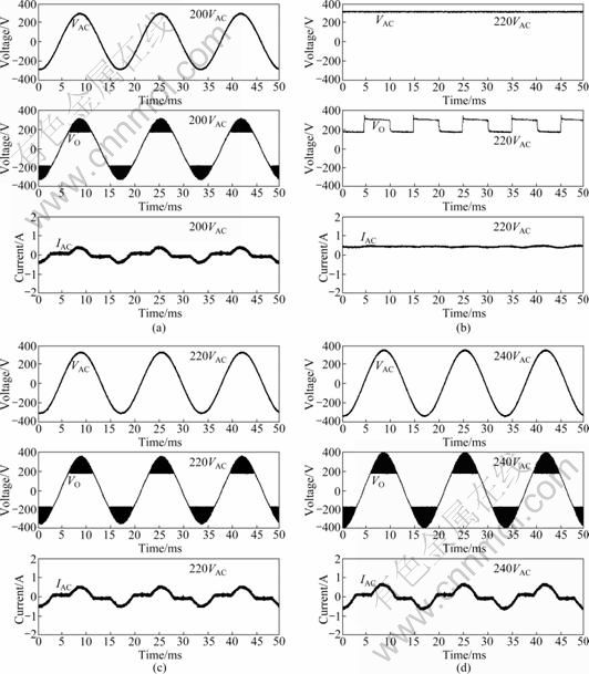
Fig. 8 Waveforms of proposed PWM dimmer with EMI filter: (a) Typical waveforms; (b) Expanded waveforms; (c) Under voltage flicker with lower voltage of 200 V AC power supply; (d) Under voltage flicker with higher voltage of 240 V AC power supply
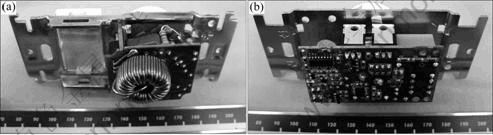
Fig. 9 Photographs of phase-controlled and PWM dimmer: (a) Phase-controlled dimmer; (b) PWM dimmer
5 Conclusions
1) Compared with the previous phase-controlled dimmer, the proposed PWM dimmer can generate correct sine wave and reduce the third harmonic current from 81.6% to 47.3%. Moreover, it is controlled by the input voltage independently and does not amplify the light flicker during dimming.
2) The proposed novel dimmer can be used in various AC directly driven LED lamps. Experimental results show that instead of the previous phase-controlled dimmer, the proposed PWM dimmer can be used for the residential and commercial lighting dimmer models.
References
[1] ONUSHKIN G A, LEE Young-jin, YANG Jung-ja, KIM Hyung-kun, SON Joong-kon, PARK Gil-han, Park Yong-jo. Efficient alternating current operated white light emitting diode chip [J]. IEEE Photonics Technology Letter, 2009, 21(1): 33-35.
[2] CHO Jae-hee, JUNG Jae-wook, JUNG Hye-chae, KIM Hyung-kun KIM Hyun-soo, LEE Jeong-wook, YOON Su-kho, SONE Cheol-soo, JANG Tae-woon, PAK Yong-jo, YOON Eui-joon. Alternating current light emitting diodes with a diode bridge circuitry [J]. Japanese Journal of Applied Physics, 2007, 46(2): L1194-L1196.
[3] YEN H H, YEH W Y, KUO H C. GA N alternating current light emitting device [J]. Physical Status Solid A, 2007, 204(6): 2077- 2081.
[4] AO Jing-ping, SATO H, MIZOBUCHI T, KAWANO S, MORIOKA K, MURAMOTO Y. Monolithic blue LED series arrays for high-voltage AC operation [J]. Physical Status Solid A, 2002, 194(2): 376-379.
[5] JIANG H, LIN J, JIN S. Light emitting diodes for high AC voltage operation and general lighting. US Patent 6957899 [P]. 2005-10-25.
[6] SMITH J, SPEAKES J, RASHID M H. An overview of the modern light dimmer: Design, operation, and application [C]// Proceedings of the 37th Annual North American IEEE Power Symposium. Iowa, USA, 2005: 299-303.
[7] WANG C S. Flicker-insensitive light dimmer for incandescent lamps [J]. IEEE Transaction Industry Electronics, 2008, 55(2): 767-772.
[8] DATTA S. Power pollution caused by lighting control system [C]// Proceedings of IEEE Industry Applications Society Annual Meeting. Detroit, USA, 1991: 1842-1852.
[9] WANG C S, DEVANEY M J. Incandescent lamp flicker mitigation and measurement [J]. IEEE Transaction of Instrument Measurement, 2004, 53(4): 1028-1034.
[10] BURKHART R M, OSTRODKA D L. Reverse phase-controlled dimmer for incandescent lighting [J]. IEEE Transaction Industry Application, 1979, IA-15(5): 579-581.
[11] DARANET Z. Power line harmonic problems�CCauses and cures [M]. Dranets Technologies, 1994.
[12] DATTA S. Power pollution caused by lighting control system [C]// Proceedings of IEEE Industry Applications Society Annual Meeting. 1991: 1842-1852.
[13] CHRISTIANSEN C F, BENEDETTI M. Power FET controlled dimmer for incandescent lamps [J]. IEEE Transaction Industry Application, 1983, 19(3): 323-327.
[14] RASHID M H. Power electronics: Circuits, devices, and applications [M]. 3rd Ed. Pearson Education, 2004: 309.
(Edited by DENG L��-xiang)
Received date: 2011-05-24; Accepted date: 2011-10-10
Corresponding author: SONG Eui-ho, Professor, PhD; Tel: +82-55-213-3666; E-mail: ehsong@changwon.ac.kr
Abstract: A new dimmer using a mental-oxide-semiconductor field-effect transistor (MOSFET) for alternating-current (AC) directly driven light-emitting-diode (LED) lamp was presented. The control method of proposed dimmer is pulse width control (PWM) method. Compared with the conventional phase-controlled dimmer, the proposed PWM dimmer can produce sine wave and did not cause harmonics problem. Furthermore, the proposed control method did not amplify the light flicker due to the independence of input voltage. Therefore, the PWM dimmer can be used as the dimmer of the AC LED lamp instead of the conventional phase- controlled dimmer. The experimental result shows that the proposed PWM dimmer has good performances.
