

J. Cent. South Univ. (2018) 25: 1513-1523
DOI: https://doi.org/10.1007/s11771-018-3844-2

Radiation pattern analyses of circular aperture antenna to generate radio orbital angular momentum
LIN Cheng-long(�ֳ���)1, LIN Ming-tuan(������)1, LIU Pei-guo(�����)1, TANG Xing(����)2
1. College of Electronic Science, National University of Defense Technology, Changsha 410073, China;
2. Army Agency Office of Nanjing Army, Nanjing 210000, China
 Central South University Press and Springer-Verlag GmbH Germany, part of Springer Nature 2018
Abstract:
Circular aperture antenna recently has been regarded as a nature source to generate high power radio orbital angular momentum (OAM) in millimeter (mm) wave; however, the radiation pattern was not investigated. Theoretical derivation of radiation pattern of circular aperture OAM antenna is conducted to evaluate the performance. Extensive simulations verify the validity of the theoretical result. Furthermore, performance of such antenna excited by orthogonal TE and TM modes is compared, which shows the potential application for TEg1 mode to create pure OAM g�C1 mode in a practical system, providing guidance for generation of twisted radio waves in mm-wave bands.
Key words:
Cite this article as:
LIN Cheng-long, LIN Ming-tuan, LIU Pei-guo, TANG Xing. Radiation pattern analyses of circular aperture antenna to generate radio orbital angular momentum [J]. Journal of Central South University, 2018, 25(6): 1513�C1523.
DOI:https://dx.doi.org/https://doi.org/10.1007/s11771-018-3844-21 Introduction
Radio orbital angular momentum (OAM) [1] has been widely studied to be used in communication and radar system, which provides more freedom degrees compared to the present technology. The twisted wave carrying OAM has helical phase profiles, with different OAM modes orthogonal to each other, which can be used to improve the communication speed [2, 3]. Benefiting from the different phase responses, rich information of the target can be achieved when using vortex radar [4, 5].
To obtain the twisted wave, several kinds of antennas were designed. The primary way to obtain OAM used the twisted parabolic antenna with modified shape in azimuth direction to obtain the helical phase profile [6]. Another main method to create OAM utilized the uniform circular array (UCA), with each unit fed by the same amplitude but successive phase. Eight-patche antenna array operating at 10 GHz was fabricated to verify the feasibility of the UCA for generation of OAM [7]. For general circular array not limited to UCA, theoretical solution of feeding design to produce OAM was derived in our recent work [8]. Later, another paper of us [9] demonstrated a UCA-based OAM steering technology to solve the misalignment problem between the transmitter and receiver.Employing the higher resonated mode, the ability of a circular patch antenna to generate OAM at 2.4 GHz was proved in Ref. [10]. Based on a reflective metasurface [11], twisted radio wave was achieved and measured at 5.8 GHz. Meta- surface can be also used to produce high quality OAM mode [12, 13].
OAM-based multiplexing is also another hot topic of radio OAM. An outdoor experiment using two modes OAM multiplexing and demultiplexing, had been conducted to verify the advantage of OAM multiplexing [14]. A 32-Gb/s millimeterwave link over 2.5 m with OAM multiplexing at 28 GHz was reported in Ref. [15]. Based on traveling circular-wave antennas [16], antennas carrying four OAM modes were designed for OAM-multiplexing in Ref. [17]. To increase the communication distance, partial aperture sampling receiver with reduced size was studied in Ref. [18].
While in radar regime, target detection model based on OAM has also attracted increasing attention since it was proposed in Ref. [19]. The OAM-based radar [20, 21] employed a UCA to produce twisted beams to illuminate objects in the far-field, providing a new perspective to estimate azimuth information of targets without any relative moves or beams scanning required by traditional radars. To further increase resolution of the OAM-based radar technique, multiple signal classification algorithm was introduced in our recent studies [22, 23], showing great robustness and enhancement.
Compared to low frequency bands, antenna to generate OAM in millimeter-wave bands is more difficult. The UCA method in such high frequency band is hard as the compact array would increase the complexity of feeding network. However, combing the spiral phase plate and the array concept, a novel method to generate mixed OAM modes at 98 GHz was proposed in Ref. [24], by drilling the holes in a specific distribution of the plate. A travelling circular wave antenna was designed at 60 GHz to be used in the dual OAM multiplexing experiment in Ref. [25]. A natural source to produce high power OAM in mm-wave was reported in Ref. [26], which used the circular aperture antenna with gyrotron structure. This method makes the fabrication of mm-wave OAM antenna easy. However, more attention was paid on the gyrotron structure to generate OAM mode rather than the radiation pattern, which is significant for communication application, therefore requiring further study. In this work, theoretical derivation and analysis are conducted, and then verified by the simulation results.
This work is organized as follows. The introduction of radio OAM development is first made in Section 1. The theoretical derivation of radiation pattern of circular aperture antenna to generate OAM is conducted in Section 2. In Section 3, the feasibility of gyrotron structure to produce the required orthogonal mode is demonstrated. Extensive simulations are made in Section 4 to verify the theoretical derivation, with conclusions drawn in Section 5.
2 Theoretical derivation
The far field of circular aperture antenna as shown in Figure 1 can be calculated according to the Huygens field equivalence principle by using the equivalent electric- and magnetic-current Js and Ms in its transverse cross section. The �� and f components of electric and magnetic field in (r, ��, f) are given [27]:
 (1)
(1)
where Es�� and Es�ա� are the radial �� and azimuthal �ա� components of electric field source in transverse cross section of an aperture antenna, respectively; ��, k and �� are the wavelength, wave number and wave impedance in free space, respectively. Based on orthogonal TEgh modes, a circular waveguide is proved in Ref. [28] to have the ability to generate OAM mode g, and the E-field inside the waveguide is given by
 (2)
(2)
where is the hth solution of
 a is the radius of the circular aperture;
 A is the feeding amplitude.

Figure 1 Circular aperture antenna
By substituting Eq. (2) to Eq. (1), the far-filed radiation pattern of this aperture antenna can be obtained. First consider the calculation of
 (3)
(3)
Similarly, the other part can be calculated as:
 (4)
(4)
Therefore, it can be derived that
 (5)
(5)
Similar result of �� component of electric field can be achieved:
 (6)
(6)
Given that most of OAM-based communication systems use linear polarization, here the derivation concerns more about the x- and y-component of E-field which are formulated as:
 (7)
(7)
From Eq. (7), it can be found that the OAM mode is determined by the ratio of  For larger u, mode g�C1 will be engendered, and for smaller u mode g+1 plays the dominated role, while for a moderate ratio mode g�C1 and g+1 will be merged. The field excited by orthogonal TM modes can be obtained by using the same derivation method as TE modes, of which the �� component of E-field can be formulated as:
 (8)
(8)
and �� component can be achieved as follows:
 (9)
(9)
The analyses of u are the same as TE modes, which is not stated here.
3 Generation of orthogonal modes by gyrotron structure
However, the excitation of orthogonal modes is a difficult problem. Based on the interaction between gyrating electron beams in external magnetic field and fast wave in the vacuum tubes, the gyrotron oscillator [29, 30] is proved to have the ability to produce the orthogonal modes in a circular waveguide, which is also the most promising mm-wave source in producing the high power energy with high efficiency. This can be seen from Eq. (11) in Ref. [29], which has a similar structure with the Eq. (2). Also, the gyrotron was experimentally verified in Ref. [26] to generate OAM in mm-wave, which proposed a QO-mode generator for low power measurement. Here a more common scheme of gyrotron structure to generate OAM mode is briefly introduced, which is shown in Figure 2. In the gun coil magnets, electrons are emitted by the cathode, which are then accelerated in the main magnet. While the electron beam travels through the intense magnetic field and the electrons start to gyrate at a specific frequency given by the strength of the magnetic field. Radiation is strongly amplified in the cavity after the interaction between gyrating electron beam and radio wave. The electron beam is then dissipated in the collector. By changing the strength of the magnetic field, the orthogonal modes can be tuned.
With the assistance of the CST particle studio, the excitation of the orthogonal modes by the gyrotron oscillator can be simulated. By employing the paticle-in-cell (PIC) solver, it is not necessary to simulate the cathode for generation of electron. The main part of the simulation is about the cavity region where the interaction happens, which can be seen in Figure 3. A cavity with radius tapered from r1 to r2, as shown in Figure 3(b), is used for mode convertor. According to the configuration in Ref. [31], different orthogonal modes as shown in Figure 4 can be generated by changing the magnetic field.
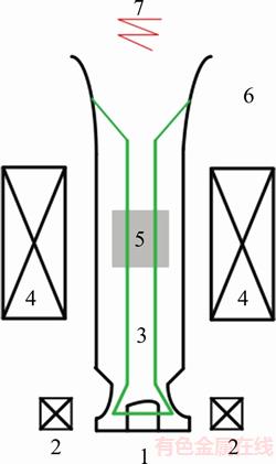
Figure 2 Scheme of a basic gyrotron: 1�CCathode; 2�CGun coil magnets; 3�CElectron beam; 4�CMain magnet; 5�CCavity region; 6�CCollector; 7�CRadiation

Figure 3 Perspective layout of gyrotron in CST simulation (a) and cross section of tapered cavity (b)
The gyrotron oscillator can achieve different high power levels and modes at millimeter-wave bands [32]. This highly developed technique can be directly used in the excitation of orthogonal mode in a circular waveguide.

Figure 4 E-field vector of high orthogonal modes generated by gyrotron:
4 Simulation results and analyses
As the CST particle studio has no ability to obtain the radiation pattern, simulations by CST microwave studio are conducted to verify the theoretical derivation in this section. This is because the orthogonal modes generated by gyrotron structure can be equivalently produced by using the combination function of CST microwave studio, which can simulate the radiation pattern. Additionally, factors that affect the radiation pattern and the phase profile such as the TE or TM modes are analyzed. For gyrotron-based antenna, the resonant frequency is close to the cut-off frequency for different modes. Please note that here a more general radiation pattern of circular aperture OAM antenna rather than only gyrotron-based OAM antenna is studied. Based on superposition of the field excitations by the CST Microwave studio, it is easy to obtain the radiation patterns of the circular aperture OAM antenna at a specific frequency.
4.1 Production of OAM based on orthogonal TEg1 modes
Figure 5(a) presents the ratio u for 3 different orthogonal TE modes, i.e., TE21, TE31 and TE41. The radius of the circular aperture antenna is 20 mm, and the radiation pattern and the phase profile are simulated at 30 GHz, which is higher than cut-off frequencies of all the simulated TE or TM modes. The dominant role of mode g�C1 within �ȡ�20��, �ȡ�30��, �ȡ�35�� areas for TE21, TE31 and TE41 can be observed. While the curve valleys imply that the twisted radio beams are dominated by the main OAM mode g+1. The influence of radii a on u is plotted in Figure 5(b), of which a common TE21 mode is used. It is noted that u decreases slowly when a=10 mm, implying that at most area mode g�C1 mode plays the key role. For a larger radius, the dominated area of mode g�C1 becomes narrower. Since the beamwidth of the main beam is narrow for a large size aperture antenna, the dominated area of mode g�C1 is also narrow. Please note that the following simulations are based on the circular aperture antenna with radius 20 mm.

Figure 5 u for different TE modes using 20 mm raius aperture antenna (a), and different aperture radii using TE21 mode (b)
Figure 6 compares the normalized 2-D radiation patterns obtained by the theoretical derivation and by CST simulation. The theoretical derivation is simulated by Matlab. It can be found that both radiation patterns have the similar structure of the typical twisted radio wave, namely, the gain in the central area is pretty low. The open angles of all the main beams for both two methods are almost the same. There is only a minor difference of amplitude for these two approaches. The 3-D radiation patterns of different modes can be seen in Figure 7. It can be observed that a wider angle of the main beam and lower gain can be achieved with a higher mode, which is consistent with the 2-D radiation pattern. Figure 8 draws the helical phase profile of E-field (x-component) obtained by CST, with aperture antenna excited by orthogonal TEg1 modes. The observation area with a size of 70 mm��70 mm is located 140 mm far from the aperture antenna. It can be found that in the observation area TEg1 mode can engender OAM mode g�C1. The intensity patterns of three modes are shown in Figure 9. By observing Figure 5(a) and Figure 6, it can be viewed that the main beams in Figure 6 have larger u as shown in Figure 5(a) for predominated OAM mode g�C1, free of the influence of OAM mode g+1. This exhibits that circular aperture antenna carrying orthogonal TEg1 mode can produce g�C1 OAM mode within the main beams, while for certain areas out of main beam it will be affected by OAM mode g+1.
4.2 Influence of different h
As derived in Section 2, orthogonal TEgh has the potential to generate OAM mode g�C1 and g+1.
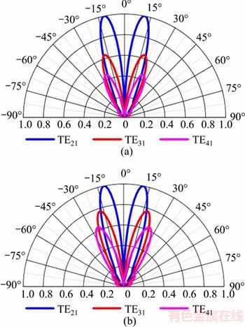
Figure 6 2-D radiation patterns of E-field with Matlab (a) and CST (b)
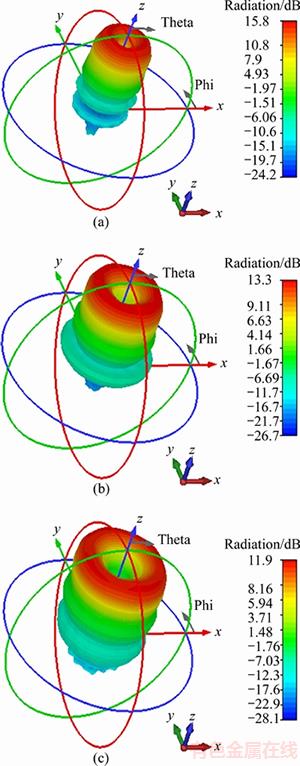
Figure 7 3-D radiation patterns of different OAM mode 1 (a), 2 (b) and 3 (c) generated by orthogonal TE21, TE31 and TE41 mode respectively
Here TE2h modes are chosen to evaluate the influence of different h on the OAM mode generation. The ratio u in Figure 10(a) indicates a narrower area (u>6 dB) for generation of pure OAM mode g�C1 when h=2, 3, beyond which OAM mode g+1 will pose the influence and cause the ambiguity.The radiation pattern in Figure 10(b) suggests that for h=2, 3 only small part of energy is focused on OAM mode g�C1 in the central beams, while most energy is radiated on the area where OAM mode g�C1 and g+1 are mixed. By observing the central beams excited by TE22 and TE23 in Figure 10(b), it can be found that the open angle of the OAM mode g�C1 is the same as that of TE21. The 3-D radiation pattern shown in Figure 11 also exhibits the side lobes between the main beams when excited by TE modes with higher h, which is consistent with the 2-D radiation pattern. The phase profiles of x-component E-field excited by orthogonal TE22 and TE23 modes are depicted in Figure 12. For both two modes, helical phase profile of mode g=1 is only obvious within a small central area of the observation panel, and is polluted by OAM mode g=3 for most other areas.
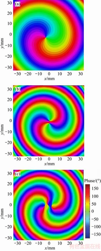
Figure 8 Helical phase profiles of OAM modes 1 (a), 2 (b) and 3 (c) generated by orthogonal TE21, TE31 and TE41 mode respectively

Figure 9 Intensity profiles of OAM modes 1 (a), 2 (b) and 3 (c) generated by orthogonal TE21, TE31 and TE41 mode respectively
4.3 Production of OAM based on orthogonal TMg1 modes
The phase profiles of E-field excited by orthogonal TMg1 modes are illustrated in Figure 13. g�C1 helical phase arms in the narrow central panel can be observed, which extends to g+1 arms outwards, manifesting the predominant role of OAM mode g�C1 in the central area and the g+1 mode in the outside area.

Figure 10 u (a) and 2-D radiation pattern (b) for different TE2h modes
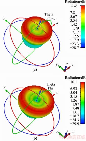
Figure 11 3-D radiation pattens excited by orthogonal TE22 (a) and TE23 (b)
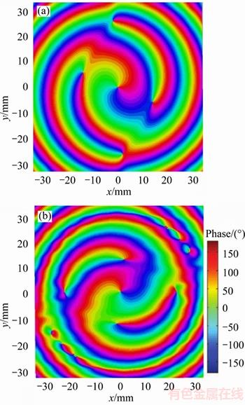
Figure 12 Phase profiles excited by orthogonal TE22 (a) and TE23 (b) modes
The radiation pattern in Figure 14 shows that the OAM mode g�C1 is radiated from the central beam as shown in the blown-up area, which is quite small compared to the OAM mode g+1 in the main beam. It can be concluded that circular aperture antenna excited by orthogonal TMg1 mode can produce main OAM mode g+1 in the main beam and OAM mode g�C1 in the small central beam. Similar trend as TE modes can be observed in the 3-D radiation patterns in Figure 15. For circular aperture antenna excited by a TM mode with higher h, wider angle of main beam and lower gain is expected. However, the radiation pattern does not show the small central side lobes. This is because the gain level is quite small compared to the main beam; therefore it is easy to be ignored especially when the gain is expressed by log not linear formation.
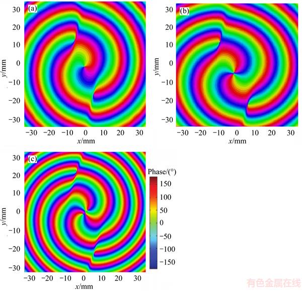
Figure 13 Phase profiles excited by orthogonal TM21 (a), TM31 (b) and TM41 mode (c)
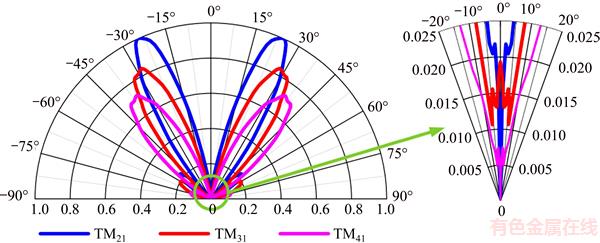
Figure 14 2-D radiation patterns for different TM modes
5 Conclusions
1) The radiation pattern of circular aperture antenna to generate OAM was studied, with the theoretical results verified by the CST simulation.
2) Pure OAM mode g�C1 within main beam has been obtained with excitation of orthogonal TEg1 mode, while for other TEgh (h>1) mode excitation OAM mode g�C1 and g+1 were mixed.
3) TM g1 mode could also produce OAM mode g�C1 but only within a narrow central area and its main beam was dominated by the OAM mode g+1.
4) Therefore, the TEg1 mode is more applicable as the excitation than other TE or TM modes in practical OAM-based communication systems. The study of the radiation pattern of circular aperture antenna will enrich the theory of radio OAM.
Acknowledgment
The authors would like to thank Lecturer LI Xiang in the School of Electronic Engineering and Computer Science, Queen Mary University of London for his stimulating discussions.
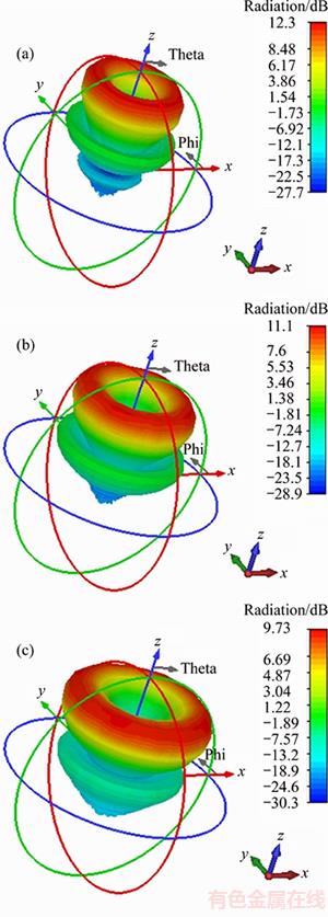
Figure 15 3-D radiation pattens excited by orthogonal TM21 (a), TM31 (b) and TM41 (c)
References
[1] Thid�� B, Then H, Sj holm J, PALMER K BERGMAN J, CAROZZI T D, ISTOMIN Y N, IBRAGIMOV N H, KHAMITOVA R. Utilization of photon orbital angular momentum in the low-frequency radio domain [J]. Physical Review Letters, 2007, 99(8): 087701.
[2] Gao X, Huang S, Zhou J, WEI Y, GAO C, ZHANG X, GU W. Generating, multiplexing/demultiplexing and receiving the orbital angular momentum of radio frequency signals using an optical true time delay unit [J]. Journal of Optics, 2013, 15(10): 5401.
[3] XU C, ZHENG S, ZHANG W, CHEN Y, CHI H, JIN X, ZHANG X. Free-space radio communication employing OAM multiplexing based on rotman lens [J]. IEEE Microwave and Wireless Components Letters, 2016, 26(9): 738�C740.
[4] LIU K, CHENG Y, LI X, WANG H, QIN Y, GAO Y. Spinning target detection using OAM-based radar [C]// International Workshop on Electromagnetics: Applications and Student Innovation Competition. IEEE, 2017: 29�C30.
[5] LIU K, LI X, CHENG Y, GAO Y, FAN B, JIANG Y. OAM-based multitarget detection: From theory to experiment [J]. IEEE Microwave and Wireless Components Letters, 2017, 99: 1�C3.
[6] MARI E, SPINELLO F, OLDONI M, RAVANELLI R A, ROMANATO F, PARISI G. Near-field experimental verification of separation of OAM channels [J]. IEEE Antennas & Wireless Propagation Letters, 2015, 14: 556�C558.
[7] Bai Q, Tennant A, Allen B. Experimental circular phased array for generating OAM radio beams [J]. Electronics Letters, 2014, 50(20): 1414�C1415.
[8] Lin M, Gao Y, Liu P, LIU J. Theoretical analyses and design of circular array to generate orbital angular momentum [J]. IEEE Transactions on Antennas & Propagation, 2017, 65(7): 3510�C3519.
[9] Lin M, Gao Y, Liu P, GUO Z. Performance analyses of the radio orbital angular momentum steering technique based on Ka-band antenna [J]. International Journal of Antennas and Propagation, 2017, 2017(6): 1�C12.
[10] Barbuto M, Trotta F, Bilotti F, TOSCANO A. Circular polarized patch antenna generating orbital angular momentum [J]. Progress in Electromagnetics Research, 2014, 148: 23�C30.
[11] Yu S, Li L, Shi G, ZHU C, ZHOU X, SHI Y. Design, fabrication, and measurement of reflective metasurface for orbital angular momentum vortex wave in radio frequency domain [J]. Applied Physics Letters, 2016, 108(12): 5448.
[12] CHEN M L N, JIANG L J, SHA W E I. Artificial perfect electric conductor-perfect magnetic conductor anisotropic metasurface for generating orbital angular momentum of microwave with nearly perfect conversion efficiency [J]. Journal of Applied Physics, 2016, 119: 064506.
[13] CHEN M L N, JIANG L J, SHA W E I. Ultrathin complementary metasurface for orbital angular momentum generation at microwave frequencies [J]. IEEE Transactions on Antennas & Propagation, 2017, 65(1): 396�C400.
[14] TAMBURINI F, MARI E, SPONSELLI A, ROMANATO F, BO T, BIANCHINI A, PALMIERI L, SOMEDA C G. Encoding many channels in the same frequency through radio vorticity: First experimental test [J]. New Journal of Physics, 2011, 14(3): 811�C815.
[15] YAN Y, XIE G, LAVERY M P, HUANG H, AHMED N, BAO C, REN Y, CAO Y, LI L, ZHAO Z. High-capacity millimeter-wave communications with orbital angular momentum multiplexing[J]. Nature Communications, 2014, 5: 4876.
[16] ZHENG S, HUI X, JIN X, CHI H, ZHANG X. Transmission characteristics of a twisted radio wave based on circular traveling-wave antenna [J]. IEEE Transactions on Antennas & Propagation, 2015, 63(4): 1530�C1536.
[17] ZHANG W, ZHENG S, HUI X, CHEN Y, JIN X, CHI H, ZHANG X. Four-OAM-mode antenna with traveling-wave ring-slot structure [J]. IEEE Antennas & Wireless Propagation Letters, 2017, 16: 194�C197.
[18] HU Y, ZHENG S, ZHANG Z, CHI H, JIN X, ZHANG X. Simulation of orbital angular momentum radio communication systems based on partial aperture sampling receiving scheme [J]. Iet Microwaves Antennas & Propagation, 2016, 10(10): 1043�C1047.
[19] GUO G, HU W, DU X. Electromagnetic vortex based radar target imaging [J]. Journal of National University of Defense Technology, 2013(6): 71�C76. (in Chinese)
[20] LIU K, CHENG Y, YANG Z, WANG H, QIN Y, LI X. Orbital-angular-momentum-based electro-magnetic vortex imaging [J]. IEEE Antennas and Wireless Propagation Letters, 2015, 14: 711�C714.
[21] LIU K, LIU H, QIN Y, CHENG Y, WANG S, LI X, WANG H. Generation of OAM beams using phased array in the microwave band [J]. IEEE Transactions on Antennas & Propagation, 2016, 64(9): 3850�C3857.
[22] LIN M, GAO Y, LIU P, LIU J. Super-resolution orbital angular momentum based radar targets detection [J]. Electronics Letters, 2016, 52(13): 1168�C1170.
[23] LIN M, GAO Y, LIU P, LIU J. Improved OAM-based radar targets detection using uniform concentric circular arrays [J]. International Journal of Antennas and Propagation, 2016, 2016(6): 1�C8.
[24] Cheng L, Hong W, Hao Z C. Generation of electromagnetic waves with arbitrary orbital angular momentum modes [J]. Scientific Reports, 2014, 4: 4814.
[25] Hui X, Zheng S, Chen Y, HU Y, JIN X, HAO C, ZHANG X. Multiplexed millimeter wave communication with dual orbital angular momentum (OAM) mode antennas [J]. Scientific Reports, 2015, 5: 10148.
[26] Sawant A, Choe M S, Thumm M, CHOI E M. Orbital angular momentum (OAM) of rotating modes driven by electrons in electron cyclotron masers [J]. Scientific Reports, 2017, 7: 3372.
[27] Collin R. Foundations for microwave engineering [M]. Berlin: VEB Verlag Technik, 1973.
[28] Berglind E, Bjork G. Humblet��s decomposition of the electromagnetic angular moment in metallic waveguides [J]. IEEE Transactions on Microwave Theory & Techniques, 2014, 62(4):779�C788.
[29] Huang Y, Li H, Du P, LIU S. Third-harmonic complex cavity gyrotron self-consistent nonlinear analysis [J]. IEEE Transactions on Plasma Science, 1997, 25(6): 1406�C1411.
[30] Yong H, Li H, Yang S, LIU S. Study of a 35-GHz third-harmonic low-voltage complex cavity gyrotron [J]. Acta Electronica Sinica, 2000, 27(2): 368�C373.
[31] Li X, Lang J, Alfadhl Y, CHEN X. 3D PIC simulation of starting process of oscillation in a 42 GHz gyrotron [C]// Millimeter Waves and Thz Technology Workshop. IEEE, 2013: 1�C2.
[32] THUMM M K A. Recent developments on high-power gyrotrons��Introduction to this special issue [J]. Journal of Infrared Millimeter & Terahertz Waves, 2011, 32(3): 241�C252.
(Edited by YANG Hua)
���ĵ���
Բ�οھ����߲�������Ƕ����ķ������Է���
ժҪ��Բ�οھ����߽�������Ϊ���ں��ײ�Ƶ�β������и߹��ʵ�Ź���Ƕ�������Ȼ��ʽ֮һ�����ǣ�Ŀǰ���о���û�и����������ߵķ������Է��������Ĵ����۽Ƕ��Ƶ��˲�������Ƕ�����Բ�οھ����ߵķ������ԣ���ͨ������ʵ����֤�����۽����ȷ�ԡ��������ģ(TE)�ͺ��ģ��TM��������Բ�οھ����ߵķ���ʵ������� TEg1���Բ�������g�C1ģ̬�Ĺ���Ƕ��������ʺ���ʵ��Ӧ����ʹ�á����ĶԸ������ߵķ��������ں��ײ���Ų������IJ������о��ͷ�����
�ؼ��ʣ�����Ƕ�������Ų����������ײ���Բ�οھ����ߣ��������ԣ����ģ�����ģ
Received date: 2018-01-10; Accepted date: 2018-05-11
Corresponding author: LIN Cheng-long, PhD Candidate; E-mail: chenglonglin08@163.com; ORCID: 0000-0002-3039-0244
Abstract: Circular aperture antenna recently has been regarded as a nature source to generate high power radio orbital angular momentum (OAM) in millimeter (mm) wave; however, the radiation pattern was not investigated. Theoretical derivation of radiation pattern of circular aperture OAM antenna is conducted to evaluate the performance. Extensive simulations verify the validity of the theoretical result. Furthermore, performance of such antenna excited by orthogonal TE and TM modes is compared, which shows the potential application for TEg1 mode to create pure OAM g�C1 mode in a practical system, providing guidance for generation of twisted radio waves in mm-wave bands.
