

J. Cent. South Univ. (2019) 26: 241-255
DOI: https://doi.org/10.1007/s11771-019-3997-7

Pseudo-static analysis of cantilever retaining walls using upper bound limit analysis approach
Asadollah RANJBAR KARKANAKI1, Navid GANJIAN1, Farajollah ASKARI2
1. Department of Civil Engineering, Science and Research Branch, Islamic Azad University, Tehran, Iran;
2. Iran International Earthquake Engineering Institute, Tehran, Iran
 Central South University Press and Springer-Verlag GmbH Germany, part of Springer Nature 2018
Abstract:
Given the extensive utilization of cantilever retaining walls in construction and development projects, their optimal design and analysis with proper attention to seismic loads is a typical engineering problem. This research presents a new algorithm for pseudo-static analysis of retaining walls employing upper bound method. The algorithm can be utilized to design and check the external and internal stability of the wall based on the proposed mechanism. One of the main features of this algorithm is its ability to determine the critical condition of failure wedges, the minimum safety factor and maximum force acting on the wall, as well as the minimum weight of the wall, simultaneously, by effectively using the multi-objective optimization. The results obtained by the proposed failure mechanisms show that, while using the upper bound limit analysis approach, the active force should be maximized concurrent with optimizing the direction of the plane passing through the back of the heel. The present study also applies the proposed algorithm to determine the critical direction of the earthquake acceleration coefficient. The critical direction of earthquake acceleration coefficient is defined as the direction that maximizes the active force exerted on the wall and minimizes the safety factor for wall stability. The results obtained in this study are in good agreement with those of similar studies carried out based on the limit equilibrium method and finite element analysis. The critical failure mechanisms were determined via optimization with genetic algorithm.
Key words:
retaining wall; upper bound; pseudo-static analysis; safety factor; multi-objective optimization��
Cite this article as:
Asadollah RANJBAR KARKANAKI, Navid GANJIAN, Farajollah ASKARI. Pseudo-static analysis of cantilever retaining walls using upper bound limit analysis approach [J]. Journal of Central South University, 2019, 26(1): 241�C255.
DOI:https://dx.doi.org/https://doi.org/10.1007/s11771-019-3997-71 Introduction
Better performance of cantilever retaining walls, when compared with the gravity retaining walls, makes them a more preferable option for earthquake-prone areas. The assessment of stability and force acting on the retaining walls is a classical topic in geotechnical engineering. The existing literature in the field provides a number of different methods for evaluating the stability of retaining walls [1�C4]. In problems pertaining to the stability of retaining walls, the purpose of determining the active and passive forces acting on the walls is to investigate the internal and external stability. Most works carried out on the stability of retaining walls have ignored the passive earth pressure in front of the wall [5�C11]. Other researchers have investigated the effect of buried depth of foundation on the stability of the wall. However, in all these studies, the weight of the wall has been ignored [12�C15].
As a result of the significant effect of weight and buried depth of the wall on its safety factors, such assumptions create an error in wall stability checks, especially during the seismic analysis. In 2010, LI et al [16] assumed a failure block on a gravity wall and utilized the upper bound method to examine the wall stability against sliding. In 2011, DI SANTOLO et al [17] indicated that a change in the direction of this plane along the vertical axis changes the magnitude of active force exerted on the wall. In 2015, KLOUKINAS et al [18] investigated the seismic response and stability of a cantilever retaining wall by limit equilibrium analysis and shaking table models [18]. In this method, originated from Coulomb theory, active force on the wall is calculated by a pseudo-static analysis. Considering the presence of a heel in this wall-direction, the force is determined by assuming a vertical plane passing through the end of the heel. Therefore, to determine the most critical state of the wall stability, maximization of the active force exerted on the wall should be performed concurrently with optimizing the direction of the plane passing through the back of the heel. The seismic pressure in retaining walls can be determined using various methods [19�C24], the most famous of which is the one provided by MONONOBE and OKABE [25�C27], also known as M-O theory. In the M-O theory which is a direct expansion of Coulomb theory, vertical and horizontal forces behind the wall are determined by pseudo-static analysis. In all mentioned studies, critical failure wedges are determined based on the maximization of active force for earthquake conditions. Nevertheless, it should be noted that in actual design processes, the purpose of calculating the active and passive forces is to ensure the external stability by checking the factors of safety against sliding, overturning, and bearing capacity failure, and also to ensure the internal stability by checking the shear and bending, etc. within the wall structure; thus, in this study, the critical failure wedges are determined by the maximization of the exerted force and the minimization of the safety factor for wall stability via upper bound limit analysis. The assumptions made at the time of designing the retaining walls by limit state methods have been evaluated by different researchers [28, 29]. Coulomb introduced the concepts of plasticity to soil mechanics for the first time [30], and Rankine applied plasticity concepts to an infinite region of the soil [31]. FINN showed that the limit state methods can be employed more reliably using the results from the experimental observations [32].
Generally, in limit state methods, shape of the failure wedges in the soil behind the wall are influenced by the rotation and displacement of the wall. These results were presented in the studies by JAMES and BRANSBY for the effective force on retaining walls [33]. CHEN and ROSENFARB employed the upper bound limit method in order to determine the force exerted on retaining walls [34]. Thus far, most of the theories applied in the retaining wall design were either upper bound limit or the limit equilibrium methods [26, 35, 36]. CALTABIANO et al [37] used the limit equilibrium method to determine the sliding of the retaining wall in static and dynamic states. LI et al [38] used the upper bound limit method to investigate the seismic stability of gravity walls. Furthermore, NAMA et al [4] employed three optimization methods in order to determine the active force exerted on the retaining walls. When determining the active force of retaining walls, the calculated force would be lower than the actual failure force value if the assumed velocity field meets the consistency and boundary conditions of the problem. In the upper boundary method, both the force exerted on the wall and the wall stability are influenced by the shape of wall��s failure wedges [39]. In the conventional retaining wall design methods, the safety factor of external stability against sliding and overturning are defined as the ratio of passive to active forces. The values of both parameters are independent of wall dimensions.
In the present study, transition failure mechanisms were presented for investigating the stability of cantilever retaining walls through upper bound limit method. The proposed algorithm was also used to determine the critical direction of earthquake acceleration coefficients. In the proposed method, the impact of wall dimensions and geometry on the stability safety factors in the seismic state was investigated. This stability is the stability against sliding and deep shear failure.
2 Formulation and optimization method
Figure 1 shows the failure mechanisms used to determine the seismic stability safety factors of the retaining wall against sliding using the upper bound limit analysis method [40]. This mechanism is composed of 4 blocks that are only associated with transitional displacement.
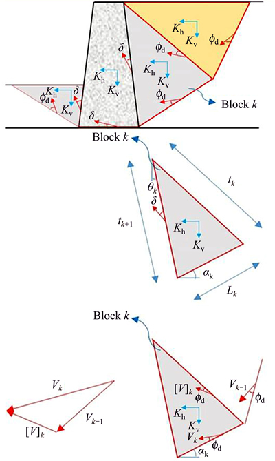
Figure 1 Failure mechanisms used to determine seismic stability and velocity vectors
Using the upper bound method requires the calculation of the increments caused in the work by external (E) and internal (Wg) loads. The work done by internal loads is calculated by Eq. (1):
 (1)
(1)
where Lk is the length of the failure line with external boundaries; tk represents the length of the failure line between two internal blocks; Vk is the absolute velocity vector of the wedge k; [V]k is the relative velocity vector between the wedges k and k�C1; fd and Cd are, respectively, reduced internal friction angle and soil cohesion, which are obtained by Eq. (2).
 (2)
(2)
while, the external work is obtained by Eq. (3).

 (3)
(3)
where ��k and Gk are the angles of the failure line of the wedge k with respect to the horizontal and the weight of the wedge k, respectively. Now, equate the work by internal and external loads and substitute Cd and fd with C and f, in which Fs is obtained from Eq. (4) by trial and error. In this equation, f is the soil friction angle and f is the soil cohesion, also kv and kh are, respectively, vertical and horizontal earthquake acceleration coefficient.
 (4)
(4)
In this study, in order to determine critical failure wedges (minimum stability safety factors, and the maximum seismic active force exerted on the wall) genetic algorithms were used for optimize the wall. The following was used as input parameters for the algorithm [40]:
Pcross= 0.7, Pmutation=0.05, Maxgen= 700, Npop=2000.
where Npop is the number of the population; Pcross is the crossover probability; Maxgen is the size of generations; Pmutation is the mutation probability.
In this study, the goal is the simultaneous optimization of safety factor for wall stability, seismic active force, and geometric dimensions of the wall, and this goal is realized through multi-objective optimization with genetic algorithm.
3 Presented failure mechanisms
3.1 Sliding mechanism
The four-block failure mechanism for determining sliding safety factor in the seismic state is presented in Figure 2.
This mechanism includes three triangular blocks and a polyhedral block C. It is evident that the weights of the wall and soil are considered in the block C. The angle of friction between concrete and the soil in the block C was assumed (��). For the mechanism to perform correctly, the extensions of the velocity vector in behind, under and front of the base with respect to the horizontal, are required to be aligned. Therefore, the extension of the velocity vector in front of and behind the base must make an angle of (�ĨCfd) with the failure surface (which is shown in the block C). The work done by internal and external forces is calculated by Eqs. (5) and (6):


 (5)
(5)


 (6)
(6)
where L is the length of the failure surface; �� and ��c are the unit weights of the soil and concrete respectively;
 �� are absolute and relative velocity vectors on failure surfaces. The values of Cd and fd are obtained from Eqs. (7) and (8):
 (7)
(7)
 (8)
(8)
where �� and C�� are obtained from Eqs. (9) and (10):
��=kfd (9)
C��=kCd (10)
In Eqs. (9) and (10), �� and C�� are, the reduced cohesion and friction angle between the soil and concrete, and values of k are normally assumed between 0 and 1.
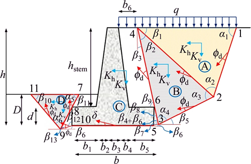
Figure 2 Four-block mechanism for determining sliding safety factor in seismic state
The velocity vectors are considered to be in the form shown in Figure 3, and are obtained from Eqs. (11) to (17). Considering the failure wedges in Figure 2, and assuming 6 that input parameters (��), the unknown parameters can be obtained. Relative and absolute velocity vectors in the upper bound limit method are similar to Figure 3 and are obtained by Eqs. (11) to (17).
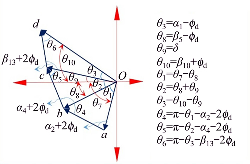
Figure 3 Relative and absolute velocity vectors for sliding stability
 (11)
(11)
 (12)
(12)
 (13)
(13)
 (14)
(14)
 (15)
(15)
 (16)
(16)
 (17)
(17)
According to principles of the upper bound method and the velocity vectors shown in Figure 3, by equating the work done by internal and external forces (given the presence of Fs on both sides of the equation), the safety factor for sliding is obtained by trial and error. In order to determine the minimum sliding safety factors for the wall, the equations were programmed using MATLAB and the minimum values for the safety factor and unknown angles were computed by the genetic algorithm.
3.2 Deep failure mechanism
The five-block failure mechanism for determining the deep shear failure safety factor in the seismic state is presented in Figure 4.
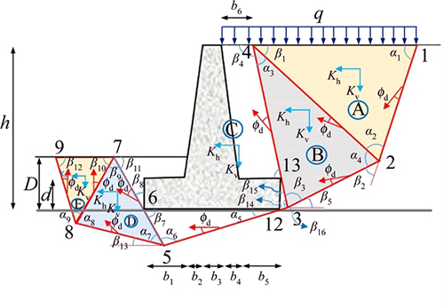
Figure 4 Mechanism for determining deep shear safety factor in seismic state
As shown in Figure 4, this mechanism includes four triangular blocks and a polyhedral block C. It is evident that the weights of the wall and soil are considered in the block C. The work done by internal and external forces is calculated by Eqs. (18) and (19):
Wg= ��{
��{ sin��9L12L24sin��2)��(1+Kv+Khcot��9)+
 sin��10L23L24sin��4)��(1+Kv+Khcot��10)+
 sin��11)��(1+Kv+Khcot��11)��[L512L56sin��6+
L67Dsin��8+2bd +(2b3+b2+b4)hstem+
2(D�Cd)b1+(b6+b5)hstem+L312L313sin��16]+
 sin��12L57L58sin��7)��(�C1�CKv+Khcot��12)�C
 sin��13L78L89sin��9)��(�C1�CKv+Khcot��9)}+
q[L14 sin��9+b6
 sin��11] (18)
E=Cdcosfd[L12+L23 +(L312+L512) +L58
 +
+
L89 +L24+(L413+L313)
 +L57
+L57 +L78
+L78 ] (19)
The velocity vectors are considered to be in the form shown in Figure 5, and are obtained by Eqs. (20) to (27). Considering the failure wedges in Figure 4, and assuming 8 input parameters (��), the unknown parameters can be obtained. Relative and absolute velocity vectors in the upper bound limit method are similar to those shown in Figure 3 and are obtained by Eqs. (20) to (27).
 (20)
(20)
 (21)
(21)
 (22)
(22)
 (23)
(23)
(24)
 (25)
(25)
 (26)
(26)
 (27)
(27)
Table 1 shows the minimum safety factors obtained based on the proposed stability mechanisms. These values have been obtained by coding the equations in MATLAB and then applying the genetic algorithm. Table 1 shows the good quality of optimization of safety factors based on the geotechnical and seismic parameters.
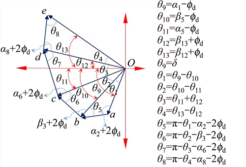
Figure 5 Relative and absolute velocity vectors for stability deep shear failure
3.3 Determining of seismic active coefficient
The seismic active force exerted on the retaining wall can be calculated based on the failure mechanism shown in Figure 6.
As Figure 6 shows, by equating the work done by internal and external forces, the seismic force (Pae) is determined by Eq. (28) based on the proposed failure mechanism.
Table 1 Minimum safety factors obtained based on proposed stability mechanisms
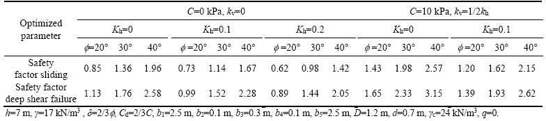
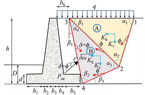
Figure 6 Failure mechanism for seismic active force
 (28)
(28)
Wg= ��sin��1
 qL13+(L12L23sin��2)��
(1+Kv+Khcot��1)+ L23L24sin��3)��
(1+Kv+Khcot��2)] (29)
E=Ccosf(L12+L24+L23+L34 (30)
(30)
According to Eq. (28), assuming four input parameters (a��s), the seismic active force values can be obtained. In order to determine the critical force exerted on the wall, the maximum active force should be computed through the genetic algorithm. The values for relative and absolute vectors based on the proposed mechanism are presented in Figure 7 and can be obtained by Eqs. (31) to (35).
 (31)
(31)
 (32)
(32)
 (33)
(33)
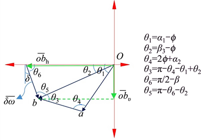
Figure 7 Velocity vectors plotted based on proposed failure mechanism
 (34)
(34)
 (35)
(35)
The values for the seismic active coefficient of the soil (Kae=Pae/[(1/2)��h2(1�CKv)]) are presented in Table 2. Based on the proposed mechanism (Figure 6), the maximum force can be determined by assuming four input parameters (the a��s) and using the genetic algorithm.
According to Figure 6, the angle ��5 can assume a range of values from negative to positive. Changing the value of angle ��5, change the seismic active coefficient. The changes of this coefficient are presented in Table 2 considering the variation of angle ��5. The results show that increasing the angle with respect to zero (positive value) increases the seismic active coefficients, and decreasing the angle with respect to zero (negative value) decreases the seismic active coefficients. It is evident that the value of angle ��5 is influenced by the length of the heel (b5). In other words, the variation of the heel length (b5) can change angle ��5 and the seismic active coefficient of the soil. In general, in order to maximize the seismic active force, failure wedges tend to make angles larger than zero with respect to the vertical (��5>0).
4 Results comparison
The results of the current research are compared with the limit equilibrium and FEM methods in Tables 3 and 4. In order to determine the safety factors in the limit equilibrium method, failure mechanisms are assumed to be circular and planar. The minimum values obtained from the analyses are presented in the tables. In the limit equilibrium method, the methods proposed by MORGENSTEN et al [41] and BISHOP [42] were used for calculation of safety factors [41, 42]. The minimum values for the safety factors are presented in Tables 3 and 4.
As shown in Tables 3 and 4, the values for safety factors obtained in the present study are lower than those determined by the limit equilibrium method. Overall, the results of the upper bound limit method are in good agreement with FEM and limit equilibrium methods. The failure mechanisms obtained both in the present study and FEM are presented in Figure 8. It should also be noted that the failure mechanisms proposed in this study are in line with that obtained through finite element analysis.
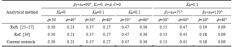
To determine the accuracy of the proposed failure mechanism (Table 5), the values obtained in this study for the seismic active force are compared with the results of other well-known methods. This comparison shows that the results of this study are quite consistent with the results [25�C27] and limit analysis of CHANG et al [39].
SHUKLA et al [43] have also developed a process for estimating the seismic active force for C-f soil. In this method, the angle friction and cohesion between the soil and wall and the depth of tensile crack are ignored. In Table 6, the results obtained in this study are compared with the results provided by SHUKLA et al [43]. This comparison shows a good agreement between the results of the present method and those provided by SHUKLA et al [43] for a variety of geotechnical and seismic profiles.
Table 2 Maximum seismic active coefficient obtained based on proposed mechanisms
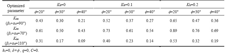
Table 3 Minimum safety factors obtained based on proposed stability mechanisms on sliding stability

Table 4 Minimum safety factors obtained based on proposed stability mechanisms on deep shear failure
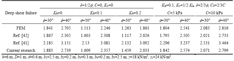
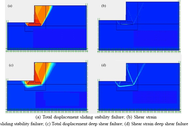
Figure 8 Failure mechanisms as determined by FEM:
Table 5 Comparison of maximum seismic active coefficient obtained based on proposed mechanisms
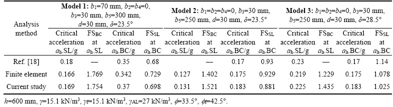
In 2015, KLOUKINAS et al [18] investigated the seismic response of cantilever retaining walls via limit equilibrium method and shaking Table tests. In Table 6, the results of the present study are compared with those obtained by KLOUKINAS et al [18] for three laboratory-sized models. In Table 7, �� is the unit weight of backfill, ��f is the unit weight of the soil under the base, ��AL is the unit weight of the aluminum wall, f is the angle of internal friction of backfill, ff is the angle of internal friction under the base, �� is the angle of friction between the soil and the base, while ah is the horizontal earthquake acceleration. Table 7 also compares the results obtained by the proposed method, finite element method, and limit equilibrium method, with respect to critical acceleration for sliding and shear failure under the base (ah.SL and ah.BC), assuming that the critical factors of safety against sliding and shear failure under the base are 1 (columns 1 and 3). Columns 2 and 4 of Table 7 present the stability safety factors obtained based on these critical acceleration coefficients. The results obtained in this study show great consistency with the results obtained by these methods.
However, it should be noted that the ultimate purpose of calculating the active force is to check the wall��s structural strength and its stability against overturning, and not just to maximize the force. This implies that when assessing the critical conditions of the wall, as well as, the magnitude of the active force, its direction should also be taken into consideration. A particular force can be assumed to cause the most critical condition for wall stability, only when its magnitude and direction are simultaneously analyzed by the optimization of failure wedges (for sliding, overturning, or deep shear failure).
Table 6 Comparison of maximum seismic active coefficient in this study with results provided by SHUKLA et al [43]
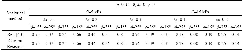
Table 7 Results of present study compared with results provided by KLOUKINAS et al [18] for three laboratory-sized models
5 Optimal geometry of wall considering critical failure mechanism
As stated in previous sections, the dimensions of the wall influence the stability safety factors and the seismic active force of the wall. Therefore, the dimensions of the wall are to be optimized at the same time as the failure mechanisms of the soil are determined (to control the seismic stability safety factors of the wall). When designing a retaining wall by the upper bound method, the designer must try to minimize the weight of the wall as one maximizes the active force and minimizes the stability safety factor. Considering the fact that multiple parameters (active force, stability safety factors and the weight of the wall) are to be optimized, a multi-objective optimization should be used in the analysis.
5.1 Determining stability safety factors of retaining wall
When designing retaining walls, in order to control external stability of the wall, the stability safety factors must be higher than the allowable values. The minimum sliding safety factors and deep shear failure of the wall were assumed 1.2 in the present study [44].
Moreover, in order to prevent overturning of the retaining wall, common methods were used to determine the safety factor. The equations presented in ACI 318-05 were used in order to control the internal stability of the retaining wall, which is determined based on the Eq. (36).
 (36)
(36)
In this study, the safety factor overturning was selected as 1.5 [44]. For optimizing the geometry of the wall and controlling the internal and external stability of the wall by the upper bound limit method, 25 parameters are to be optimized based on the proposed failure mechanisms according to Table 8.
Table 8 Parameters optimized based on proposed mechanisms

Figure 9 shows the dimensions of an example retaining wall optimized by MATLAB, while simultaneously, the stability safety factors of the wall were controlled. It also shows the shape of the failure wedges.
According to Figure 9, the critical failure wedges for determining the seismic active force of the wall are displayed in blue, the critical failure wedges for determining the sliding safety factor of the wall are displayed in green and the critical failure wedges for determining the deep shear failure of the wall are shown in red. The optimal dimensions obtained in this study are presented in Table 9 along with the those obtained by the common wall design method (limit equilibrium). FSr is the sliding safety factor; FSt is the overturning safety factor; Fsbc is the safety factor deep shear failure.
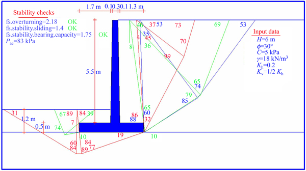
Figure 9 Critical failure wedges for determining seismic active force of wall (output MATLAB)
Table 9 Optimal dimensions obtained in this study, as well as those obtained by common wall design method
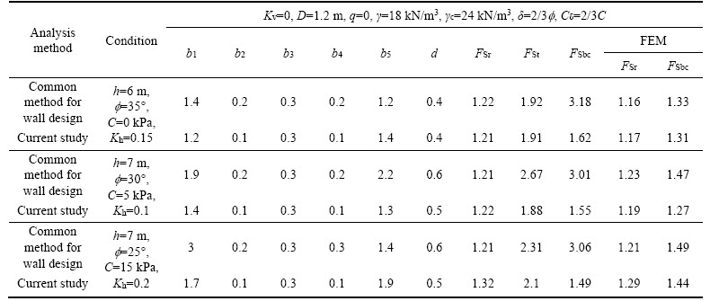
In the common method for designing retaining walls (limit equilibrium), the minimum safety factors for overturning, sliding and bearing capacity were assumed in accordance with regulations 1.5, 1.2, and 3 [45]. The stability safety factors in FEM, the limit equilibrium method (the common design method) and the upper bound limit method (the present study) are compared in Table 10.
According to Table 10, the dimensions of the wall were first optimized by the limit equilibrium method and then, considering the obtained optimal dimensions, the safety factors were calculated by FEM and upper bound limit methods. In all cases, the results show the safety factors obtained by the upper bound limit method to be larger than the minimum values allowed by the regulations and to have good agreement with FEM results. Therefore, the upper bound limit method (based on the proposed mechanisms), provides the optimal dimensions for the retaining wall that are close to the results of the limit equilibrium method. However, further investigations following the present study can offer the minimum allowed safety factors for controlling the external stability of cantilever retaining walls using the upper bound limit method.
The results show that the proposed algorithm can be used for designing the cantilever retaining walls through simultaneous examination of stability factors along with internal stability checks. One feature of this algorithm is that in the presence of complex loading and layering conditions behind or under the base, as well as, the presence of a near-surface hard layer or other complex conditions, the retaining wall can still be designed for C-f soil with just some changes in formulation.6 Critical direction of earthquake force for instability of retaining walls
When designing the retaining walls using the upper bound and limit equilibrium methods, a hypothetical mechanism should be selected for calculating the minimum values of the safety factor for wall stability. In the seismic design of these walls, the results are influenced not only by the shape of the failure mechanism, but also by the magnitude and direction of the earthquake coefficients. The direction of the resultant seismic acceleration varies from one earthquake to another. Although HOUSNER [46] claimed that Kv��(1/2�C 2/3) kh for most earthquakes, current practice tends to assume that the seismic acceleration is essentially horizontal (��=0��). The effect of this assumption on the results of analyses depends on how much the most critical direction differs from the horizontal direction, how the actual seismic acceleration differs from the horizontal and what is the magnitude of the earthquake.
In 1990, CHEN et al [29] determined the critical direction of the earthquake acceleration coefficient. They attempted to determine the earthquake acceleration direction that maximizes the active force exerted on the wall. Nevertheless, the goal of maximizing the force is to minimize the safety factor for wall stability. Therefore, in this study, the critical direction of the earthquake acceleration coefficient is assumed to maximize the active force and minimize the stability safety factors. The resultant acceleration of earthquake is defined according to Eq. (37):
 (37)
(37)
where Kh is the horizontal earthquake acceleration coefficient, and Kv is the vertical earthquake acceleration coefficient, which gives the direction of earthquake acceleration as shown in Eq. (38):
 (38)
(38)
To determine the critical direction and magnitude of seismic force, the parameters (����) are defined in Eq. (39):
 (39)
(39)
In this equation, (Kae)��=0 represents the value of seismic active force coefficient when the earthquake acceleration coefficient (k) has a horizontal orientation. Changing the direction of earthquake with respect to horizon will change the value of ����. Critical direction of the earthquake acceleration (��cr) is defined as the direction that maximizes the value of ����.
Table 10 Values of stability safety factors in FEM, limit equilibrium method (common design method) and upper bound limit method (present study)
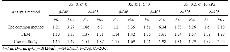
Figure 10 shows the values of normalized Kae against the values of �� for different earthquake coefficients based on the failure mechanisms discussed in the previous sections. The results indicate that as k increases, so does ������s rate of decline, and the maximum (Kae)��=��cr can be observed in ��=30��C45��.

Figure 10 Changes in parameter ���� for normalized value of seismic active force coefficient
Figure 11 illustrates the changes in direction of earthquake acceleration versus parameter ���� for normalized stability safety factors. The results indicate that determining the critical acceleration direction with the purpose of minimizing the stability safety factor yields a ��cr equal to 15��C30�� (to the horizontal). Changing the values of the earthquake coefficient and increasing or decreasing ��, increases the rate of change in ����, which are negligible around ��cr. So these values can be suggested as the critical direction to be employed when designing the cantilever retaining walls with the purpose of minimizing their stability safety factors.
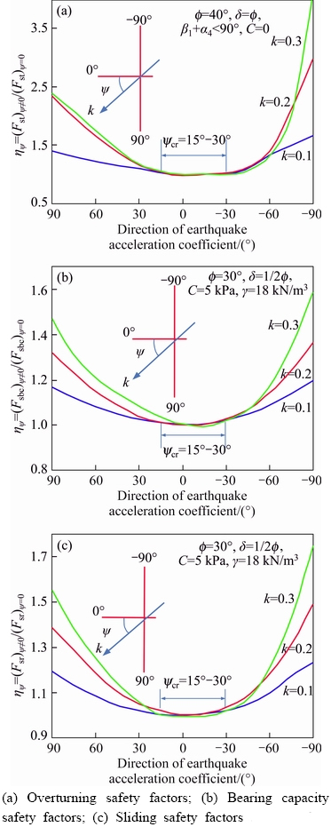
Figure 11 Changes in parameter ���� for normalized:(h=6, b1=2.5, b2=0.2, b3=0.3, b4=0.2, b5=2.5, D=I, d=0.6, ��c=24 kN/m3)
Generally, the results indicate that the exertion of vertical earthquake acceleration not only increases the magnitude of the resultant acceleration, but can also changes the direction of the resultant acceleration towards critical orientation, thereby reducing the wall stability safety factor.
Given that the maximum acceleration in majority of earthquakes is horizontal and that most relationships and software, commonly applied for designing the cantilever retaining walls, have been formulized such that they require vertical and horizontal acceleration coefficients as inputs, the critical earthquake acceleration direction is substituted into Eq. (38) to obtain the critical vertical acceleration coefficient as expressed in Eq. (40):
Kv=Khtan��cr (40)
In this case, is obtained by Eq. (40).Therefore, assuming that , it will lead to the resultant earthquake coefficient to align with critical orientation. The safety factors for controlling the external stability of cantilever retaining walls will be minimized by the upper bound limit method. The results obtained in this study are in line with the results of Husner, who
proposed for vertical earthquake coefficients.
7 Conclusions
1) The present study presented a new algorithm for pseudo-static analysis of retaining walls using the upper bound method. This algorithm can be utilized to design and check the external and internal stability of the wall based on the proposed mechanism.
2) Comparing the findings of the current research with the results of other studies showed that the results obtained from the upper bound method are consistent with those of similar studies conducted based on the limit equilibrium method and finite element analysis.
3) The results showed that the dimensions of the wall influence the stability safety factors and the seismic active force of the wall. Therefore, the dimensions of the wall are to be optimized at the same time as the failure mechanisms of the soil are determined (to control the seismic stability safety factors of the wall). When designing a retaining wall by the upper bound method, the designer must try to minimize the weight of the wall as one maximizes the active force and minimizes the stability safety factor.
4) The results showed that the exertion of vertical earthquake acceleration not only increases the magnitude of the resultant acceleration, but also pushes the direction of the resultant acceleration towards the critical orientation and reduces the wall stability safety factor. Determining the critical direction of the earthquake acceleration with the purpose of minimizing the stability safety factor gives ��cr=(15��C30��) (to the horizontal). Therefore, these values can be suggested as the critical direction to be utilized when designing the cantilever retaining walls with the purpose of minimizing their stability safety factors.
5) In this study, the stability safety factor, seismic active force, and geometric dimensions of the wall were simultaneously optimized via multi- objective optimization with genetic algorithm.
References
[1] YEPES V, ALCALA J, PEREA C, GONZALEZ-VIDOSA F. A parametric study of optimum earth-retaining walls by simulated annealing [J]. Engineering Structures, 2008, 30(3): 821�C830.
[2] CERANIC B, FRYER C, BAINES R. An application of simulated annealing to the optimum design of reinforced concrete retaining structures [J]. Computers & Structures, 2001, 79(17): 1569�C1581.
[3] SHEIKHOLESLAMI R, KHALILI B G, SADOLLAH A, KIM J H. Optimization of reinforced concrete retaining walls via hybrid firefly algorithm with upper bound strategy [J]. KSCE Journal of Civil Engineering, 2016, 20(6): 2428�C2438.
[4] NAMA S, SAHA A K, GHOSH S. Parameters optimization of geotechnical problem using different optimization algorithm [J]. Geotechnical and Geological Engineering. 2015, 33(5): 1235�C1253.
[5] ZENG X, STEEDMAN R S. Rotating block method for seismic displacement of gravity walls [J]. Journal of Geotechnical and Geoenvironmental Engineering, 2000, 126(8): 709-717.
[6] CHOUDHURY D, AHMAD S M. Stability of waterfront retaining wall subjected to pseudo-static earthquake forces [J]. Ocean Engineering, 2007, 34(14): 1947-1954.
[7] AHMAD S M, CHOUDHURY D. Seismic rotational stability of waterfront retaining wall using pseudodynamic method [J]. International Journal of Geomechanics, 2010, 10(1): 45-52.
[8] BASHA B M, BABU G L. Seismic rotational displacements of gravity walls by pseudodynamic method with curved rupture surface [J]. International Journal of Geomechanics, 2009, 10(3): 93-105.
[9] BASHA B M, BABU G L. Optimum design of bridge abutments under seismic conditions: Reliability-based approach [J]. Journal of Bridge Engineering, 2010, 15(2): 183-195.
[10] SIDDHARTHAN R, ARA S, NORRIS G M. Simple rigid plastic model for seismic tilting of rigid walls [J]. Journal of Structural Engineering, 1992, 118(2): 469-487.
[11] NOURI H, FAKHER A, JONES C. Development of horizontal slice method for seismic stability analysis of reinforced slopes and walls [J]. Geotextiles and Geomembranes, 2006, 24(3): 175-187.
[12] POWRIE W. Limit equilibrium analysis of embedded retaining walls [J]. Geotechnique, 1996, 46(4): 709-723.
[13] DIAKOUMI M, POWRIE W. Mobilisable strength design for flexible embedded retaining walls [J]. Geotechnique, 2013, 63(2): 95-106.
[14] AL A L, SITAR N. Seismic earth pressures on cantilever retaining structures [J]. Journal of Geotechnical and Geoenvironmental Engineering, 2010, 136(10): 1324-1333.
[15] AULBACH B, ZIEGLER M, SCHUTTRUMPF H. Design aid for the verification of resistance to failure by hydraulic heave [J]. Procedia Engineering, 2013, 57: 113-119.
[16] LI Xin-po, YONG Wu, HE Si-ming. Seismic stability analysis of gravity retaining walls [J]. Soil Dynamics and Earthquake Engineering, 2010, 30(10): 875�C878.
[17] DI SANTOLO A S, EVANGELISTA A. Dynamic active earth pressure on cantilever retaining walls [J]. Computers and Geotechnics, 2011, 38(8): 1041�C1051.
[18] KLOUKINAS P, DI SANTOLO A S, PENNA A, DIETZ M, EVANGELISTA A, SIMONELLI A L. Investigation of seismic response of cantilever retaining walls: Limit analysis vs shaking table testing [J]. Soil Dynamics and Earthquake Engineering, 2015, 77: 432�C445.
[19] CHENG Y. Seismic lateral earth pressure coefficients for c�C�� soils by slip line method [J]. Computers and Geotechnics, 2003, 30(8): 661�C670.
[20] YANG X L. Upper bound limit analysis of active earth pressure with different fracture surface and nonlinear yield criterion [J]. Theoretical and Applied Fracture Mechanics, 2007, 47(1): 46�C56.
[21] EVANGELISTA A, DI SANTOLO A S, SIMONELLI A L. Evaluation of pseudostatic active earth pressure coefficient of cantilever retaining walls [J]. Soil Dynamics and Earthquake Engineering, 2010, 30(11): 1119�C1128.
[22] ZHANG J M, SONG F, LI D J. Effects of strain localization on seismic active earth pressures [J]. Journal of Geotechnical and Geoenvironmental Engineering, 2009, 136(7): 999�C 1003.
[23] ISKANDER M, CHEN ZC, OMIDVAR M, GUZMAN I. Rankine pseudo-static earth pressure for c�Cf soils [J]. Mechanics Research Communications, 2013, 51: 51�C55.
[24] SHAMSABADI A, XU S Y, TACIROGLU E. A generalized log-spiral-Rankine limit equilibrium model for seismic earth pressure analysis [J]. Soil Dynamics and Earthquake Engineering, 2013, 49: 197�C209.
[25] MONONOBE N. Consideration into earthquake vibrations and vibration theories [J]. Journal of the Japan Society of Civil Engineers, 1924, 10(5): 1063�C1094.
[26] OKABE S. General theory of earthquake pressure and seismic stability of retaining wall and dams [J]. J Japanese Soc of Civil Engng. 1924, 10(6): 1277�C1323.
[27] MONONOBE N, MATSUO H, EDITORS. On the determination of earth pressures during earthquakes [C]// Proceedings, World Engineering Congress. Tokyo, Japan, 1929: 176.
[28] HILL R. A theory of the yielding and plastic flow of anisotropic metals [C]// Proceedings of the Royal Society of London A: Mathematical, Physical and Engineering Sciences. The Royal Society, 1948: 281�C297.
[29] CHEN W F, LIU X. Limit analysis in soil mechanics [M]. Amsterdam: Elsevier, 2012.
[30] COULOMB C. Essay on maximums and minimums of rules to some static problems relating to architecture [DB]. 1973.
[31] RANKINE WM. On the mathematical theory of the stability of earth-work and masonry [J]. Proceedings of the Royal Society of London, 1857, 8(1): 60�C61.
[32] FINN W. Applications of plasticity in soil mechanics [J]. Journal of Soil Mechanics & Foundations Division, 1967, 93(5): 101�C120.
[33] JAMES R, BRANSBY P L. Experimental and theoretical investigations of a passive earth pressure problem [J]. Geotechnique, 1970, 20(1): 17�C37.
[34] CHEN W, ROSENFARB J. Limit analysis solutions of earth pressure problems [J]. Journal of the Japanese Society of Soil Mechanics and Foundation Engineering, 1973, 13(4): 45�C60.
[35] RICHARS R, HUANG C, FISHMAN K L. Seismic earth pressure on retaining structures [J]. Journal of Geotechnical and Geoenvironmental Engineering, 1999, 125(9): 771�C778.
[36] SHERIF M A, FANG Y S. Dynamic earth pressures on walls rotating about the top [J]. Journal of the Japanese Society of Soil Mechanics and Foundation Engineering, 1984, 24(4): 109�C117.
[37] CALTABIANO S, CASCONE E, MAUGERI M. Static and seismic limit equilibrium analysis of sliding retaining walls under different surcharge conditions [J]. Soil Dynamics and Earthquake Engineering, 2012, 37: 38�C55.
[38] LI X, SU L, WU Y, HE S. Seismic stability of gravity retaining walls under combined horizontal and vertical accelerations [J]. Geotechnical and Geological Engineering, 2015, 33(1): 161�C166.
[39] CHANG M, CHEN W F. Lateral earth pressures on rigid retaining walls subjected to earthquake forces [M]. School of Civil Engineering, Purdue University, 1981.
[40] KARKANAKI A R, GANJIAN N, ASKARI F. Stability analysis and design of cantilever retaining walls with regard to possible failure mechanisms: An upper bound limit analysis approach [J]. Geotechnical and Geological Engineering. 2017, 35(3): 1079�C1092.
[41] MORGENSTERN N, PRICE V E. The analysis of the stability of general slip surfaces [J]. Geotechnique, 1965, 15(1): 79�C93.
[42] BISHOP A W. The use of the slip circle in the stability analysis of slopes [J]. Geotechnique, 1955, 5(1): 7�C17.
[43] SHUKLA S K, GUPTA S K, SIVAKUGAN N. Active earth pressure on retaining wall for c-f soil backfill under seismic loading condition [J]. Journal of Geotechnical and Geoenvironmental Engineering, 2009, 135(5): 690�C696.
[44] AASHTO L. LRFD bridge design specifications. Washington, DC: American Association of State Highway and Transportation Officials. 1998.
[45] INSTITUTE A C. Building code requirements for structural concrete (ACI 318-05) and commentary (ACI 318R-05) [S]. American Concrete Inst, 2004.
[46] HOUSNER, G W. Strong ground motion [C]// WIEGEL R L. Earthquake Engineering. New York: Prentice-Hall, NY, 1974: 75�C91.
(Edited by HE Yun-bin)
���ĵ���
��������������������ʽ����ǽ����α��������
ժҪ����������ʽ����ǽ�ڽ���Ϳ�����Ŀ�еĹ㷺Ӧ�ã��������ǵ�����ص��Ż���ƺͷ�����һ�����͵Ĺ������⡣���������һ�������������е���ǽ�⾲�����������㷨�����㷨�����ڻ��ڸû���ǽ�������ȶ�����ƺ�У�ˡ����㷨����Ҫ�ص�֮һ���ܹ���Ч�����ö�Ŀ���Ż���ͬʱȷ��ʧЧШ����ٽ�������������ǽ���ϵ���С��ȫϵ��������������Լ�ǽ�����С���������������ʧЧ�������õ��Ľ����������ʹ��������������ʱ�������������Ӧͬʱ����ͨ��ǽ����ƽ�淽����Ż������Ļ�Ӧ�ø��㷨ȷ���˵�����ٶ�ϵ�����ٽ緽������ٶ�ϵ�����ٽ緽����Ϊ������ǽ���ϵ�����������Ա�֤ǽ���ȶ��İ�ȫϵ����С�����о��������ڼ���ƽ�ⷨ������Ԫ�����������о����һ�£�ͨ���Ŵ��㷨�Ż�ȷ���˹ؼ�ʧЧ���ơ�
�ؼ��ʣ�����ǽ�����ޣ�α��̬�ķ�������ȫϵ������Ŀ���Ż�
Received date: 2017-02-14; Accepted date: 2017-06-26
Corresponding author: Navid GANJIAN, PhD, Lecturer; Tel: +98-21-44868401-9; E-mail: n.ganjian@srbiau.ac.ir
Abstract: Given the extensive utilization of cantilever retaining walls in construction and development projects, their optimal design and analysis with proper attention to seismic loads is a typical engineering problem. This research presents a new algorithm for pseudo-static analysis of retaining walls employing upper bound method. The algorithm can be utilized to design and check the external and internal stability of the wall based on the proposed mechanism. One of the main features of this algorithm is its ability to determine the critical condition of failure wedges, the minimum safety factor and maximum force acting on the wall, as well as the minimum weight of the wall, simultaneously, by effectively using the multi-objective optimization. The results obtained by the proposed failure mechanisms show that, while using the upper bound limit analysis approach, the active force should be maximized concurrent with optimizing the direction of the plane passing through the back of the heel. The present study also applies the proposed algorithm to determine the critical direction of the earthquake acceleration coefficient. The critical direction of earthquake acceleration coefficient is defined as the direction that maximizes the active force exerted on the wall and minimizes the safety factor for wall stability. The results obtained in this study are in good agreement with those of similar studies carried out based on the limit equilibrium method and finite element analysis. The critical failure mechanisms were determined via optimization with genetic algorithm.
