
Trans. Nonferrous Met. Soc. China 24(2014) 2737-2751
Solidification characteristics and hot tearing susceptibility of Ni-based superalloys for turbocharger turbine wheel
Zhao-xia SHI, Jian-xin DONG, Mai-cang ZHANG, Lei ZHENG
School of Materials Science and Engineering, University of Science and Technology Beijing, Beijing 100083, China
Received 2 August 2013; accepted 3 December 2013
Abstract:
The solidification characteristics and the hot tearing susceptibility were investigated on two Ni-based superalloys for turbocharger turbine wheel, K418 and K419. The segregation behaviors of the alloying elements and the precipitation phases were also studied. The results show that the solidification behavior of K419 alloy is complicated when compared with K418 due to the interdendritic segregation of many kinds of strong interdendritic partitioning elements in the remaining liquid at the final stage of solidification. The segregation of multiple elements in interdendritic liquid results in an extremely low solidus in K419. A long residual liquid stage is found during the solidification of K419, giving rise to reduced cohesion strength of dendrites and increased sensitivity to hot tearing. A hot tearing susceptibility coefficient (HTS) criterion is proposed based on a hot tearing sensitive model. The HTS value of K419 alloy is larger than that of K418 alloy.
Key words:
solidification; hot tearing susceptibility; Ni-based superalloys; segregation;
1 Introduction
K418 and K419 were developed in 1970s and used as vanes and blades for gas turbine and turbocharger turbine. Due to their excellent high-temperature strength at elevated temperature, favorable comprehensive properties and good structure stability and reliability in a wide range of temperature, they can be used in the form of precision cast hot end turbocharger turbine wheel in automotive and shipping industry. As a multi-component alloy, the constituents of K419 are complex because of the more �á� forming elements and solid solution strengthening elements when it comes to comparison with K418 alloy. In general, the operating temperature of K419 is slightly higher than that of K418.
The turbine wheels are cast into final products by the investment casting process. Due to the complexity of the turbine wheel, particularly the changes of cross-sectional dimensions of the blades, crack occurs in the blade by casting turbine wheel. The bad castability resulting from hot tearing phenomenon leads to a low rate of finished products about 85% of K418 turbine wheel in foundries, and that of K419 is much lower.
Comprehensive coverage of results reported in the literature over the past few decades on the methods of studying hot tearing and mechanical properties of semi-solid aluminium alloys was reviewed in detail by ESKIN and KATGERMAN [1,2]. The fundamental mechanisms associated with the formation of hot tearing are analyzed and the hot tearing susceptibility is predicted. Hot tearing arises from a complex combination of thermal-mechanical and solidification phenomena [3], basically being associated with the incomplete liquid feeding and tensile stress generated in coherent regions of mushy zones, more specifically, in areas with a high solid fraction of 0.9 and beyond [4]. It is generally believed that hot tearing occurs above the solidus temperature when the volume fraction of solid is 85%-95% and the solid phase is organized in a continuous network of grains and propagates in the interdendritic liquid film [1,5,6].
Some alloys show similar freezing behavior but quite different hot tearing susceptibility [7], demonstrating that the size of the freezing range cannot be used alone to evaluate the resistance to hot tearing. NIYAMA [8] and FEURER [9] considered the hindered feeding of the solid phase by the liquid as the main cause of hot tearing, that is, hot tearing will not occur as long as there is no lack of feeding during solidification. CLYNE and DAVIES [10] defined a cracking susceptibility coefficient based on a critical time spent by the mushy zone in the critical region. ZHOU et al [11] used CLYNE and DAVIES��s model to predict the hot tearing susceptibility of Mg-Zn alloys and the simulation results are in agreement with the experimental results. Although there is a general agreement that hot tearing occurs during the later stages of solidification when the freezing metal contains only a small fraction of remaining liquid, different liquid fractions at the critical stage were assumed by different authors [4,12].
In consideration of the casting technology, the hot tearing of K418 turbine has been investigated [13], but very limited information regarding the solidification characteristic of the two alloys can be found [14], much less the forming mechanism of hot tearing. Since the formation of hot crack is closely linked with the solidification process, it is necessary to study the phenomena that occur during the solidification to reveal the hot tearing mechanism and the root cause of different tendency to hot tearing.
The most direct way to get insight into the solidification and hot tearing is by examination of the microstructural evolution in the freezing range, or rather the critical region of the freezing range [7,15]. The microstructure evolution and solidification characteristics of K418 and K419 alloy were investigated by differential scanning calorimetry (DSC) analysis, isothermal solidification quenching and optical metallographic examination. Hot tearing phenomenon was investigated by analyzing the fracture of the hot crack. A modified Clyne-Davies HTS criterion was proposed to quantitatively explain the different hot tearing susceptibility of the superalloys.
2 Experimental
2.1 DSC measurement
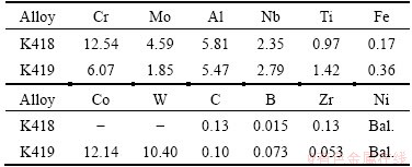
The chemical compositions of K418 and K419 alloys used are listed in Table 1. It was to be noted that all compositions were given in mass fraction unless otherwise stated here. The samples were taken from the as-received condition bar with 31 mm in diameter, which was produced by conventional manufacturing process comprising vacuum induction melting and casting into steel moulds under a protective argon atmosphere.
DSC measurement was performed in a Netzsch testing apparatus (model STA449C) to obtain temperatures of reactions. The heating rate was 20 ��C/min up to 1000 ��C, then 10 ��C/min up to 1450 ��C. This was followed by a cooling at 10 ��C/min down to 1000 ��C, then 20 ��C/min down to room temperature. The DSC specimens were cut from the master alloy. All tests were conducted in a purged high-purity argon atmosphere using high-purity alumina crucibles. A baseline was obtained by heating and cooling the crucible without samples according to the experimental method; the effect of the crucible was deducted by subtracting the baseline from the experimental data. The heating curve was used to obtain the solidus, and the cooling curve was used to quote the liquidus [16,17]. The phase transformations were also monitored on both the heating and the cooling curve, and the average value of the two was considered to be the phase transition temperature. The phase transition temperature was then used to select the quenching temperatures.
Table 1 Chemical compositions of tested alloys in the present experiments (mass fraction, %)
2.2 Isothermal solidification quenching
The evolution of microstructure was conducted on isothermal solidification quenched samples. Specimens for isothermal solidification quenching experiment were cylinders of d8.5 mm��7 mm cut from the alloy bars. The sample was sealed by the mixture of silica sol and alumina powders to effectively protect melts from flowing out and oxidation during melting and solidification. A schematic illustration of the isothermal solidification quenching process is shown in Fig. 1. Each sealed sample was put in an alumina burning boat and heated to 1420 ��C for 20 min to achieve complete melting and homogeneous. The sample was then rapidly quenched into a salt water bath with the concentration of 10% from different temperatures (expressed as Tq) in the freezing temperature interval obtained from the DSC data. The remaining liquid at a given temperature was quenched to offer a convenient method studying the microstructure evolution during solidification.
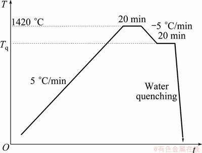
Fig. 1 Schematic of isothermal solidification quenching process
2.3 Sample examination
Quenched specimens for optical microscopy (OM) and scanning electron microscopy (SEM) were ground to 1000 grid, mechanically polished, electro-polished in a solution of H2SO4 + methanol at a voltage of 25 V for about 20 s, and electro-etched in a solution of CrO3 + H2SO4 + H3PO4 at a voltage of 5 V for about 3 s. The volume fractions of liquid in samples were measured by using an image analysis system with Photoshop CS3 software. At least six fields of view were taken at different areas of the sample and the average was taken to yield better statistical results. The solidification microstructure and the compositions of the phases at the different quenching temperatures were analyzed by scanning electron microscopy (SEM; S250MK3) with accessory energy dispersive X-ray micro-analyzer (EDXMA). The segregation behavior during solidification was quantitatively investigated by measuring the segregation coefficient of each alloying element. An electron probe micro-analyzer (EPMA; JXA-8230) was used to document the compositions of the precipitation phases at different quenching temperatures. The fracture surface of hot cracks in turbine blade was studied by SEM.
3 Results
3.1 Thermal analysis
The heating and cooling curves from DSC measurement of K418 and K419 are compared in Fig. 2. As shown in Fig. 2(a), three major phase transformations were revealed by the heating curves of the two alloys: 1) the solution of the �á� into the matrix, 2) the dissolution of carbide, and 3) the melting of the �� matrix. In K419, the dissolution of ��/�á� eutectic was also observed after the solution of �á�. Four major phase transformations during cooling were revealed by the two cooling curves: 1) the solidification of �� primary phase, 2) the precipitation of carbide, 3) the formation of ��/�á� in interdendritic areas (generally known as ��/�á� eutectic in Ni-based superalloys), and 4) the precipitation of �á� from primary ��. Detailed results from DSC measurements and the main phase transformation temperatures are listed in Table 2.
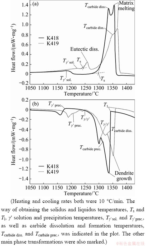
Fig. 2 DSC results for K418 and K419 during heating and cooling
3.2 Microstructure evolution
The typical microstructures for K418 during isothermal solidification are shown in Fig. 3. It was assumed that the alloy was liquid at 1350 ��C since extremely fine dendritic structures were observed when the sample was quenched from 1350 ��C (Fig. 3(a)). A certain amount of liquid had transformed into solid, in the form of fine dendritic structures in the sample quenched from 1340 ��C (Fig. 3(b)). A large quantity of coarse dendrites could be observed at 1320 ��C, indicating that the change of solid fraction in K418 at this temperature was quite quick (Fig. 3(c)). A continuous liquid network was present in the interdendritic areas at 1320 ��C. The coarse dendrites solidifying during isothermal solidification and the extremely fine dendritic structures forming during quenching process could be easily distinguished. When the sample was quenched at 1300 ��C, the solid dendrites were in an advanced stage of development and the discontinuous network restricted the free passage of liquid. A few isolated liquid pools and liquid films were present, thus the relative movement of the two phases was impossible (Fig. 3(d)). More solidified dendrites were observed at 1290 ��C, with only a small amount of liquid appearing as isolated pools and thin films (Fig. 3(e)). In Fig. 3(f), little liquid, less than 3%, was seen when the temperature dropped to 1280 ��C. This demonstrated that the K418 alloy had solidified completely at 1280 ��C, corresponding to the solidus temperature.
Table 2 Results from DSC analysis and main phase transformation temperatures
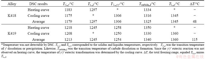
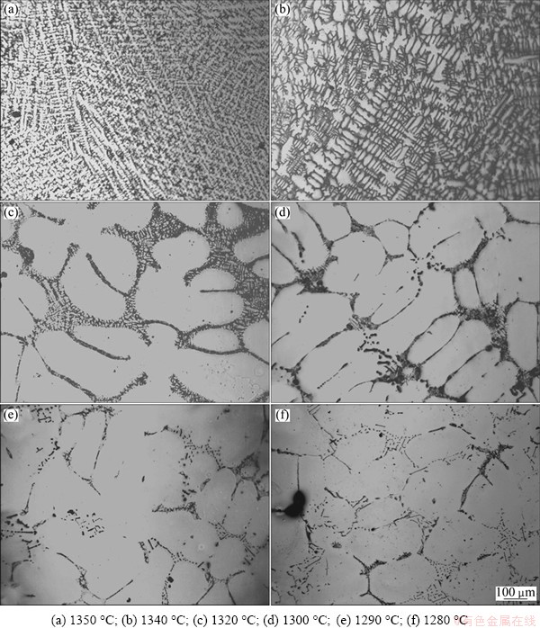
Fig. 3 Solidification microstructures of K418 quenched at different temperatures
K419 alloy maintained full liquid at 1370 ��C (Fig. 4(a)). The coarse �� dendrites were formed from liquid during the isothermal solidification at 1360 ��C, followed by the formation of extreme fine dendrites during subsequent quenching. The solidified and un-solidified regions could be easily distinguished by the coarse dendrites and the extremely fine dendrites in Fig. 4(b). The dendrites grew rapidly with decreasing temperature. As shown in Fig. 4(c), a large amount of liquid had transformed into solid when the quenching temperature dropped to 1340 ��C. A continuous liquid network was present in the interdendritic areas at this temperature. When the sample was quenched at 1320 ��C, the solid dendrites were in an advanced stage of development and the semi-continuous network restricted the free flow of liquid. A few isolated liquid pools emerged, thus the free movement of the two phases was impossible (Fig. 4(d)). The interdendritic liquid was completely discontinuous with the quenching temperature decreasing. The remaining liquid appeared as films and isolated pools (Fig. 4(e)). A long film stage together with isolated liquid pocket existed at the later stage of the solidification with the further decreasing of quenching temperature. Meanwhile, the remaining liquid volume fraction decreased slowly with temperature decreasing (Figs. 4(f)-(g)). In Fig. 4(h), little liquid, less than 3%, was seen when the temperature dropped to 1240 ��C, indicating that K419 alloy had solidified completely at this temperature.
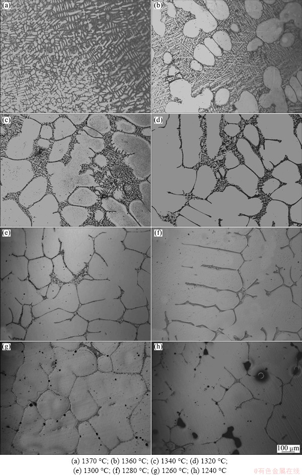
Fig. 4 Solidification microstructures of K419 quenched at different temperatures
The fractions of liquid at different temperatures of the alloys were compared quantitatively in Fig. 5. The liquid fraction of K418 changed rapidly with the quenching temperature decreasing during the entire solidification process. For K419 with bad castability, the liquid fraction decreased quickly in the interval from liquidus temperature (1370 ��C) to carbide formation temperature (1340 ��C). Nevertheless, the fraction of remaining liquid changed slowly after the formation of carbide. In other words, the final stage of solidification in K419 could be described as a long remaining liquid stage, characterizing of isolated liquid pools and thin liquid films.

Fig. 5 Fractions of remaining liquid in K418 and K419 as function of quenching temperature
3.3 Segregation behavior
The compositions of alloying elements in dendrite core and interdendritic area of K418 are listed in Table 3. The interdendritic region was significantly enriched with Ti, Nb, Mo and Zr. No obvious chemistry changes of interdendritic partitioning elements, such as Ti, Nb, Mo and Zr, in dendrite core were observed in the quenched sample. A segregation coefficient k was defined as the ratio of the average concentration of the element in the dendrite cores to that in the interdendritic regions, i.e., k=Cd/Cid [18]. The value of k less than 1 indicated that the elements segregated to the interdendritic regions and these elements were called positive segregation elements. While k values greater than 1 indicated that the elements partitioned to the dendrite cores and these elements were known as negative segregation elements [19]. The compositions of positive segregation elements in interdendritic regions during the solidification were fluctuated. Al was depleted in interdendritic area, while Cr was almost evenly distributed in dendrite core and interdendritic area. C was evidently enriched in interdendritic areas in the samples quenched at 1320 ��C and 1310 ��C. With the further decrease of quenching temperature, the uneven distribution of C was less obvious.
The compositions of alloying elements in dendrite core and interdendritic area of K419 are listed in Table 4. It is apparent that Ti, Nb, Cr, Mo, Zr and C tended to segregate towards the interdendritic regions. The content fluctuations of Ti, Nb, Cr, Mo and Zr in dendrite core were small in the quenched sample, while those in interdendritic areas were visible. Al and W were depleted in interdendritic area, while Co was almost evenly distributed. C was significantly enriched in interdendritic regions in the samples quenched at 1340 ��C and 1320 ��C. The uneven distribution of C was gradually not obvious with the quenching temperature decreasing.
Table 3 Compositions of alloying elements in dendritic core and interdendritic area of K418
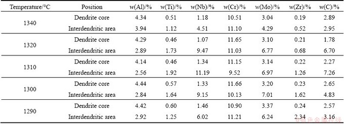
Table 4 Compositions of alloying elements in dendritic core and interdendritic area of K419
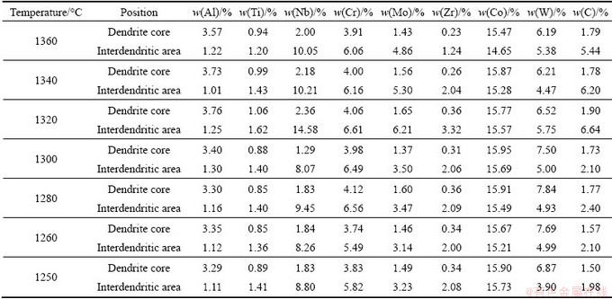
Table 5 Compositions of carbide phases in quenched samples (mole fraction, %)
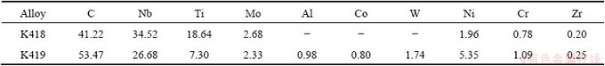
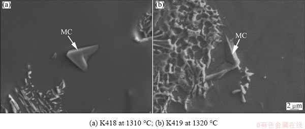
Fig. 6 Morphologies of carbide phases in quenched samples
The morphologies of carbide phases in the quenched sample are shown in Fig. 6, and the compositions determined by EPMA in precipitation particle with the aim of the determination of the carbide phase are listed in Table 5 (average value of 5 precipitation particles). The data of Table 5 showed that the precipitation phase in K418 was significantly enriched with Nb and Ti. A certain amount of Mo was also observed in the precipitation phase, while very little Ni, Cr and Zr were present. Likewise, in K419, a large quantity of Nb was seen in the precipitate, which was also enriched in Ti. It was well known that Nb and Ti were strong carbide-formers and formed the high stable carbide phase of the cubic type MC with a wide homogeneity and complete mutual solubility [17,20]. The possibility of the MC carbide formation in the investigated Ni-based superalloy was confirmed by these data.
The morphologies and EPMA mappings of the precipitations and remaining liquid in the quenched sample of K418 at 1280 ��C are shown in Fig. 7. The precipitation particles were enriched with C, B, Nb, Ti and Mo, whereas Al and Cr were seriously depleted, providing the evidence for the formation of M(C,B) carboboride phase. Due to the difficulty to detect the amount of trace light element B, the quantitative composition of the carboboride phase was not yet available in our current study. The solubility of Zr in dendrite core was very low; however, Zr was found at high concentration in the residual liquid at the final stage of solidification. A certain amount of Mo was also observed in the remaining liquid. The interdendritic segregation of C, B, Nb and Ti was less obvious finally. In general, the formation of M(C,B) was promoted by the segregation of C, B, Nb, Ti and Mo in the interdendritic liquid.
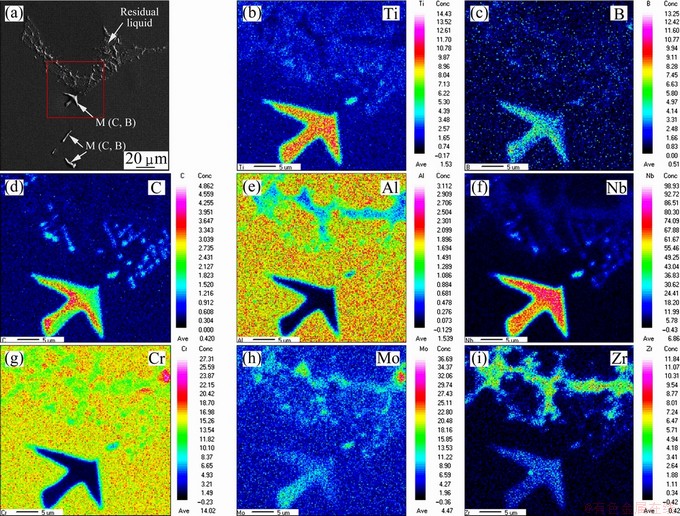
Fig. 7 Morphologies and EPMA mappings across precipitations and residual liquid in quenched samples of K418 at 1280 ��C
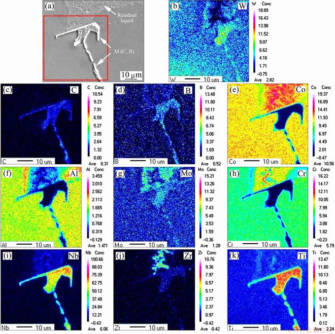
Fig. 8 Morphologies and EPMA mappings across precipitations and residual liquid in quenched samples of K419 at 1240 ��C
The morphologies and EPMA mappings of the precipitations and remaining liquid in the quenched sample of K419 at 1240 ��C are shown in Fig. 8. The precipitation particles were highly enriched with C, B, Nb, Ti and Mo, while Al, Cr and Co were seriously depleted, proving the formation and qualitative constituent of M(C,B) carboboride phase. The enrichment of C, B, Nb and Ti in the residual liquid was less obvious. Zr was almost completely expelled from dendrite core. A large quantity of Zr and a certain amount of Cr and Mo were found to be enriched in the remaining liquid.
3.4 Hot tearing characteristics
The external appearance of K418 turbine wheel is shown in Fig. 9(a). Typical macrostructure of hot tearing regions and the microstructure of crack are shown in Figs. 9(b) and (c), respectively. Because of the thin twist turbine blades with complex shape, hot tearing easily occurred in the blade. Generally, all the cracks initiated at the blade tip and developed toward the blade body. Large crack propagated very easily along the interdendritic region. The small cracks, which would probably further develop, were also observed near the large crack. Also, the growth direction of dendrite on the two side of the crack was significantly different.
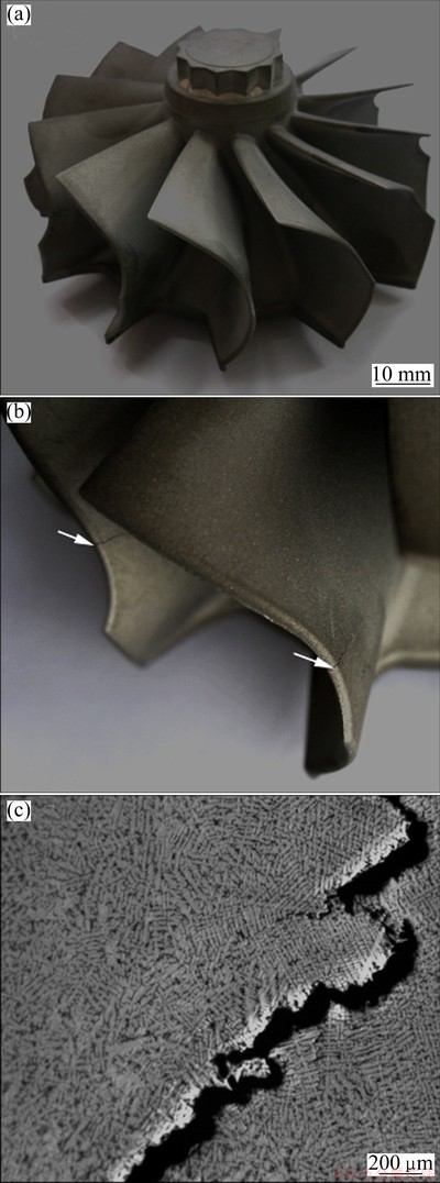
Fig. 9 Morphology of K418 turbine wheel (a), macrostructure of hot tearing in turbine blade (b) and morphology of hot tearing (c)
Typical fracture surface of crack in the turbine blade is shown in Fig. 10. It could be observed clearly that the crack formed along the interdendritic regions in both of the K418 and K419. As shown in Fig. 10(a), the fracture surface of a crack in K418 turbine wheel exhibited to be smooth in potato-like shape and dendrite-like appearance, with no cleavage planes being observed [21]. Similarly, the rounded appearance and the complete lack of cleavage planes revealed in Fig. 10(b) indicated that cracks in K419 turbine wheel formed at temperature where the dendrites arms were still covered by a more or less continuous liquid film rather than in a completely solid state [7].
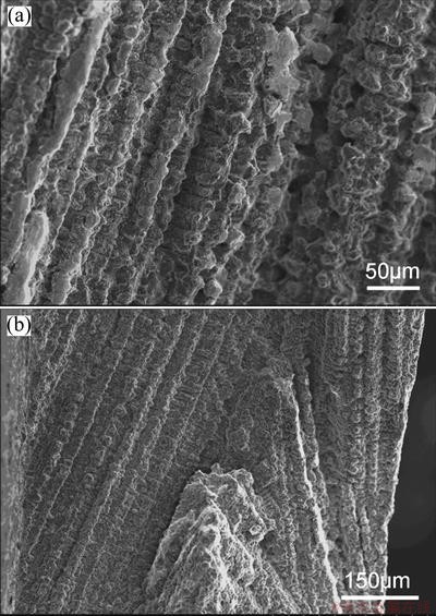
Fig. 10 Typical fracture surfaces of crack in turbine blade of K418 alloy (a) and K419 alloy (b)
4 Discussion
4.1 Solidification sequences
Actually, the microstructure of K418 observed in the quenched sample of 1350 ��C is complete liquid. The majority of the quenched microstructure at 1340 ��C is liquid, with only a certain amount of solid. Consequently, the real liquidus temperature lies between 1340 ��C and 1350 ��C. For the same reason, the liquidus temperature of K419 is between 1370 ��C and 1360 ��C. Since the isothermal solidification quenching is a rapid cooling process, the effect of undercooling (supercooling) is not negligible [16]. Thus, the carbide formation temperature and the solidus temperature obtained by isothermal solidification quenching are more or less suppressed compared with those measured by DSC analysis.
According to the microstructure evolutions during solidification, the solidification process of K418 and K419 could be described in four stages as follows [22]: 1) the formation of primary dendrite, 2) the contact of dendrite, 3) the development of dendrite and 4) the complete solidification of the remaining liquid in the interdendritic regions. One important thing to be noted here is that K419 experiences a fairly long remaining liquid stage at the final stage of solidification.
Inspection of DSC trace shows that the solidification processes of the tested alloys take place in four stages: 1) solidification commencing with the transition L���� (1345 ��C for K418 and 1360 ��C for K419); 2) solidification progressively accompanied with a reaction in the form of L����+MC (1325 ��C for K418 and 1340 ��C for K419), where M mainly represents Nb or Ti, with intensity of segregation in descending order; 3) reaction L����+MC+M(C,B), which reaction temperature cannot be determined here because the reaction peaks are too weak to be detected; and 4) termination of solidification with reaction L����+�á� (1306 ��C for K418 and 1254 ��C for K419).
The liquidus and phase transformation temperatures of K419 are higher compared with K418, which is the real difference between the two alloys. This is largely due to the higher total content of �á� forming elements and the total contents of Ti+Nb in K419. The large concentration of these elements on the one hand promotes the precipitation of �á� at higher temperature; on the other hand, facilitates the formation of primary �� from the liquid. The earlier formation of carbide in K419 also owes to the higher content of Nb and Ti.
4.2 Segregation behavior
In order to get better understanding of the segregation behavior of alloying elements, the partition coefficients are summarized in Fig. 11. In K418, alloying elements, such as Ti, Nb, Mo, Zr and C, are known to segregate to the interdendritic region, which is displayed by a partitioning coefficient k<1. The more the k value less than the homogeneous distribution coefficient which is indicated as k=1, the stronger the degree of segregation to the interdendritic liquid. On the contrary, alloying element Al, which is known to segregate to the dendrite core, would be depleted in the residual liquid with the solidification of primary �� proceeding. These elements are characterized by a partitioning coefficient k>1. The more the k value is greater than unity, the stronger the segregation tendency of the element to the solid is [23]. Cr exhibits relatively uniform distribution behaviors during the solidification. In K419, serious segregation of Nb, Mo, Zr and C is found in the initial period of solidification. Unlike K418, Cr also segregates to interdendritic liquid in K419. Thus, it is clear that alloying elements, such as Ti, Nb, Mo, Zr and C, reveal a strong partitioning tendency to interdendritic region. The positive segregation of mainly MC formers, such as Nb and Mo, is weakened after the formation of MC. The significant segregation of Cr to interdendritic liquid in K419 also results from the interaction between the various elements.
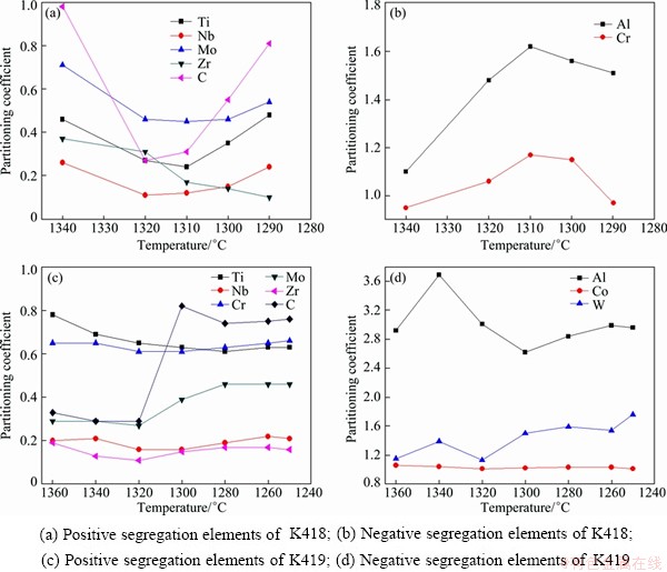
Fig. 11 Partition coefficients measured on sample quenched at different temperatures (k=Cd/Cid)
The growth of the primary �� results in the segregation. Some elements tend to accumulate to the dendrite core, while others segregate to the interdendritic liquid and then solidify as the interdendritic and eutectic regions, greatly affecting the formation and distribution of various secondary phases in the as-cast alloys [17]. Because of the segregation of solute elements and incomplete diffusion processes, the liquid phase becomes enriched with solute elements, while the solid phase remains diluted during the solidification of �� phase. The enrichment of these positive segregation elements is increased at the beginning of the solidification. As a result, when the alloy reaches its equilibrium solidus, some solute-enriched liquid still remains in the system. The strong segregation of these elements will result in the non-equilibrium solidification, thus the final stage of solidification is extended.
Carbide and carboboride commence within the interdendritic liquid when it is sufficiently accumulated with the positive segregation elements [24]. Formation of carbide particles during solidification of the alloy with the primary ��-dendrite growth takes place in the remaining liquid in interdendritic regions due to the rejection of elements, which have the partition coefficient k<1 and form the carbide phase. This is in accordance with the conclusions in Ref. [18]. The MC and M(C, B) forming elements, such as Nb, Ti, Mo, and C, will be depleted with the precipitation of carbide and carboboride during the later period of solidification, which results in the different levels of rise in partitioning coefficient of these elements. On the other hand, if a sufficient degree of segregation is further given during solidification, the residual liquid would solidify to non-equilibrium eutectic phases [25]. Besides, the positive segregation elements would be continually accumulated in interdendritic liquid during the solidification of primary �� and eventually produce the ��/�á� eutectic phase near the last stage of solidification [26,27].
The enrichment of Zr in the interdendritic residual liquid in K418 and K419 is serious during the entire solidification process, stating that Zr is grain boundary (GB) element in the tested alloys rather than phase- forming or matrix-strengthening element. Almost all of Zr element segregates to the narrow area in interdendritic region, indicating that the solubility of Zr in �� matrix is extremely low. It is unclear whether Zr exists in the form of Zr-rich phase in liquid in the two alloys based on the current research. What we can say is that the liquid pool, which finally freezes, is actually multi-component eutectic liquid, of which freezing point is very low. The solidification behavior of K419 is complicated by the interdendritic segregation of more alloying elements, such as Zr, Cr and Mo, resulting in a long isolated liquid pocket and liquid film stage during the last period of solidification, what��s more, a quite low solidus. The residual liquid existing over a wide freezing temperature range in K419 reduces the interdendritic cohesion, resulting in K419 more prone to hot tearing.
4.3 Explanation of hot tearing susceptibility
The hot tearing criterion proposed by CLYNE and DAVIES [10] is based on the theory that in the last stage of solidification, the liquid is difficult to move freely so that the strain applied during this stage cannot be accommodated by mass feeding. This last stage of freezing is regarded as the most sensitive period to hot tearing in the criterion. The hot tearing susceptibility coefficient is defined by the ratio of the vulnerable time period where hot tearing may develop, tv, and time available for the stress-relief process where mass and liquid feeding occur, tr. The hot tearing susceptibility coefficient (HTS) is proposed as
 (1)
(1)
where t0.01 is the time when the liquid fraction, fL, is 0.01; t0.1 is the time when fL is 0.1; t0.6 is the time when fL is 0.6. However, the criterion does not apply to DS superalloys in the prior studies [21]. In our research, the temperatures corresponding to the above-mentioned critical liquid fraction during the solidification of the tested alloys are listed in Table 6. Referring to Fig. 3, for K418 alloy, the liquid and solidified dendrites can move freely at 1337 ��C. As seen in Fig. 4, the movement of solid and liquid is also free at 1363 ��C in K419. That is to say, for the two alloys, it is applicable for the definition of critical liquid fraction is 0.6 when the mass and liquid feeding is possible. The free flow of liquid in K418 has been restricted at 1300 ��C; likewise, the interdendritic liquid has become discontinuous at 1320 ��C in K419. In other words, for K418 and K419, it is not suitable to take fL=0.1 as the upper limit of the vulnerable period for hot tearing. Because the Clyne-Davies criterion cannot be directly used, a modification to the Clyne-Davies criterion is tried to quantitatively illustrate the hot tearing phenomena for the two alloys.
Table 6 Temperatures corresponding to critical fL indicated in Eq. 1
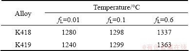
The temperature is determined by the evolution curve of liquid fraction shown in Fig. 5. One thing to note here is that the solidus temperature is considered to be the temperature when fL is 0.01.
By combining with the permeability and feeding capacity of the solid network, the solidification processes of K418 and K419 can be divided into four stages [4]:
1) Mass feeding, in which both liquid and solid are free to move. No cracking occurs at this stage.
2) Interdendritic feeding, in which a solid network is formed by the contact of dendrites. However, the remaining liquid can flow through the dendritic network. Due to the continuity of the liquid, the permeability of the network is still large enough to prevent the crack.
3) Interdendritic separation, in which the liquid network becomes fragmented, thus hot tearing may occur. Residual liquid is isolated into pockets or appears as thin film. The discontinuity of the liquid network means that the permeability of solid network becomes very small. The free flow of the liquid becomes impossible when the permeability of solid network is further weakened. Hot tearing will be induced due to the further thermal contraction of the solid.
4) Interdendritic bridging or solid feeding, in which a considerable strength has been built, thus the further contraction will be compensated by the solid-state creep and the occurrence of hot tearing can be avoided.
Interdendritic separation, this stage is considered to be the start of ��critical hot tearing range�� (CHTR). Thus, the critical liquid fraction range (CLFR), corresponding to the initiation and propagation of crack, becomes one of the key factors assessing the possibility of hot tearing. As the fraction of the residual liquid appearing as thin film is low, negligible, a model based on those liquid featured as isolated pocket in CHTR can be used for the derivation of CLFR. From the microstructure evolution of the tested alloys, most of the isolated liquid pockets are formed by the contact of adjacent three or four solidified dendrites. Due to the further random growth and contact of dendrites, the few liquid pool formed by five or more dendrites ultimately can be viewed as the pocket contacted by three or four dendrites. The hypothesis and simplification about the model are made as follows:
1) The dendrites are idealized to be equal-diameter- circles with radius of 1 unit on a two-dimensional plane.
2) The provided growth rates of the dendrites are equal.
3) Isolated liquid pool is assumed to be shaped when the dendrites contact in a tangent way.
4) An inscribed circle (centering in O) exists in the isolated liquid pocket formed in the ��interdendritic separation�� stage.
5) A considerable strength is assumed to be built when the liquid outside the inscribed circle O has solidified completely.
6) The residual liquid corresponding to the ��interdendritic bridging�� stage is approximately considered to be an inscribed circle with radius r.
The isolated liquid pocket formed by three dendrites is discussed as shown in Fig. 12. In the beginning, the dendrites (circles centering in A, B and C, respectively) and liquid are capable of relative movement (Fig. 12(a)). Isolated liquid pocket DEF is formed by the contact of the dendrites (Fig. 12(b)). The liquid fraction of isolated liquid pool DEF is recorded as fc, calculated by the area ratio of DEF to ABC, with the value of 0.093. With the successive growth of the dendrite, interdendritic bridging is formed as shown in Fig. 12(c). Magnification of the geometrical relationship in isolated liquid pool D��E��F�� is shown in Fig. 12(d). When dendrites bridge at D��, E�� and F�� (points on circle O), a considerable strength is built. Approximately, it is thought that ��OFG�צ�OF��G��, thus the value of r can be calculated according to the similar triangles principle. The liquid fraction, when interdendritic bridging can resist the stress induced by the contraction, is termed as fb. The value of fb is 0.003, equal to the area ratio of the circle of radius r to ABC. It can be seen that the liquid fraction of the isolated liquid pocket from ��interdendritic separation�� stage to ��interdendritic bridging�� stage is 0.093-0.003.
Figure 13 shows the isolated liquid pocket formed by four dendrites. At first, the dendrites (circles centering in A, B, C and D respectively) and the liquid can move freely (Fig. 13(a)). Isolated liquid pool EFGF is formed with the further growth and contact of dendrites (Fig. 13(b)). The liquid fraction of isolated liquid pool EFGH, fc, is calculated by the area ratio of EFGH to ABCD, with the value of 0.215. Bridge of dendrites is formed as shown in Fig. 13(c). According to the geometrical relationship in Fig. 13(d), it is approximately assumed that ��OHI�צ�OH��I��. The value of r can be obtained by similar triangle calculations. The liquid fraction, fb, equals the area ratio of the circle with radius r to ABCD, with the value of 0.135. The liquid fraction of the isolated liquid pocket from the ��interdendritic separation�� stage to ��interdendritic bridging�� stage is 0.215-0.135.
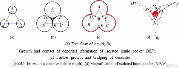
Fig. 12 Schematic diagram of calculating CLFR for isolated liquid pocket formed by three dendrites
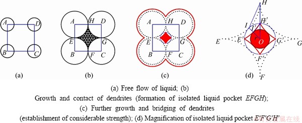
Fig. 13 Schematic diagram of calculating CLFR for isolated liquid pocket formed by four dendrites
The occurrence of isolated liquid pool contacted by four dendrites marks the start of CHTR, while the complete bridging of dendrites in the pocket formed by three dendrites can be perceived as the end of CHTR. Hence, the isolated liquid pool formed by three dendrites is taken into account to get the lower limit of CLFR, while the upper limit is obtained on account of the pocket formed by four dendrites. Thus, CLFR is determined as 0.003-0.215. The temperature corresponding to the upper limit of the CLFR, fL=0.215, is 1311 ��C for K418 and 1328 ��C for K419 in the curve plotted in Fig. 5, which is in accordance with the microstructure evolution displayed in Figs. 3 and 4. As before, it is reasonable to take fL=0.6 as the critical liquid fraction when mass and liquid feeding is possible. Therefore, a modified HTS criterion is proposed as
 (2)
(2)
where t0.003 is the time when the liquid fraction fL =0.003; t0.215 is the time when fL=0.215; t0.6 is the time when fL=0.6.
In Eq. (2), the variant fractional time at specified liquid fraction should be known to calculate the HTS. The fraction of the liquid phase as a function of temperature is revealed in Fig. 5. Besides, the cooling rate, i.e., cooling temperature as a function of time, should be determined. The simplest condition is discussed, that is, solidification with a constant cooling rate, dT/dt=constant. The cooling curves for tested alloys are shown in Fig. 14.
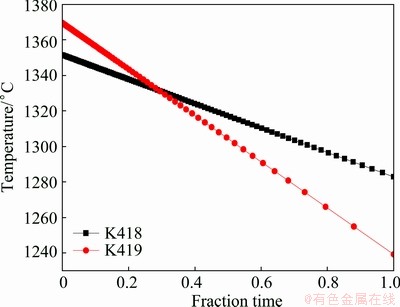
Fig. 14 Cooling curves for tested alloys under cooling conditions, dT/dt=constant
Based on the results shown in Figs. 5 and 14, and referring to Eq. (2), the graphic outlines of tv and tr for the investigated alloys are derived (Fig. 15). The value of HTS calculated from Fig. 15 is 1.14 for K418, 2.52 for K419, indicating that the hot tearing susceptibility of K419 is more than twice that of K418. In summary, it follows that bad castability is found in K419 with large tv value, increasing the time when alloy is vulnerable to hot tearing, and small tr value, permitting excellent feeding. Therefore, the modified Clyne-Davies model correlates well with the hot tearing phenomena of the Ni-based superalloys in our study. For the K419 alloy, the prior contact of dendrites results in the occurrence of isolated liquid pool and liquid film at a higher temperature. Moreover, the residual liquid rich in multiple positive segregation elements, such as Ti, Nb, Cr, Mo, Zr, C and B, is actually a complex alloy system. The strong enrichment of these elements in liquid probably leads to the formation of phase with low melting point, delaying the solidification of interdendritic liquid and generating an extremely low solidus temperature (The work in this respect will be discussed in detail in the future). In short, for K419 alloy, a long isolated liquid pocket and liquid film stage result in much less cohesion strength of the dendrites and bad castability. Since the detrimental elements, such sulfur, have been depressed to a very low level today, the particular role of Zr as a getter element in superalloys may not be so important in modern superalloys. In our present work, almost all of Zr segregates to interdendritic liquid rather than forms any phase, probably showing no more beneficial effects on the mechanical properties. The strong segregation of these alloying elements, such as Zr, Cr, Mo Ti, Nb and B to interdendritic liquid, leads to the complex solidification behavior of residual liquid, and hence the hot tearing sensitivity. Above all, to intentionally keep Zr at low levels, eliminate Zr or carefully control the so-called positive segregation elements in the tested superalloys seems to be a good suggestion to increase solidus temperature and lower the propensity to hot tearing. Therefore, future work will be concentrated on the mechanisms of the interaction and influence of alloying elements on solidification of interdendritic residual liquid and hot tearing susceptibility.
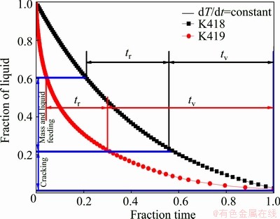
Fig. 15 Graphic outline of derivation of tr and tv for tested alloys according to modified Clyne-Davies criterion
5 Conclusions
1) The solidification sequences of K418 and K419 can be described as the solidification of �� primary phase from liquid, then the formation of carbide with MC-type, subsequently the formation of ��/�á� in interdendritic regions and finally the complete solidification of the residual liquid. Due to the higher content of �á� formers, the liquidus and phase transition temperatures of K419 are higher than those of K418.
2) Nb, Ti, Mo, Zr, B and C are strong positive segregation elements in the two alloys. The solidification behavior of K419 is complicated by the severe interdendritic segregation of elements, such as Zr, Mo and Cr, in the residual liquid, resulting in a long remaining liquid period during the final stage of solidification in K419 and an extremely low solidus. The cohesion strength of the dendrites is reduced by the interdendritic residual liquid, thus K419 is more susceptible to hot tearing.
3) Based on the microstructure evolution during solidification, a model is established to deduce the critical liquid fraction range (CLFR) in the vulnerable period to hot tearing. The CLFR for the tested alloys is 0.003-0.215, agreeing well with the experimental results. A HTS criterion is proposed to describe the hot tearing susceptibility of the tested alloys. Quantitative results show that K419 with large value of HTS is more susceptible to hot tearing.
Acknowledgements
Dr. Cun-jiang TANG is especially acknowledged for assistance with aspects of DSC data analysis and valuable discussions. Also, the authors would like to thank Prof. Fu-ming WANG for the supply of equipment for solidification experiment. Finally, the authors thank Jian-hua BIAN for her help with the operating of SEM.
References
[1] ESKIN D, KATGERMAN L. Mechanical properties in the semi-solid state and hot tearing of aluminium alloys [J]. Progress in Materials Science, 2004, 49(5): 629-711.
[2] KATGERMAN L, ESKIN D. Hot cracking phenomena in welds II [M]. Delft, The Netherlands: Springer, 2008.
[3] BELLET M, CERRI O, BOBADILLA M, CHASTEL Y. Modeling hot tearing during solidification of steels: Assessment and improvement of macroscopic criteria through the analysis of two experimental tests [J]. Metallurgical and Materials Transactions A, 2009, 40(11): 2705-2717.
[4] CAMPBELL J. Castings [M]. Burlington: Elsevier Butterworth- Heinemann, 2003.
[5] MATHIER V, DREZET J M, RAPPAZ M. Two-phase modelling of hot tearing in aluminium alloys using a semi-coupled approach [J]. Modelling and Simulation in Materials Science and Engineering, 2007, 15(2): 121-134.
[6] STANGELAND A, MO A, M��HAMDI M, VIANO D, DAVIDSON C. Thermal strain in the mushy zone related to hot tearing [J]. Metallurgical and Materials Transactions A , 2006, 37(3): 705-714.
[7] ZHANG J, SINGER R. Hot tearing of nickel-based superalloys during directional solidification [J]. Acta Materialia, 2002, 50(7): 1869-1879.
[8] NIYAMA E. Japan�CUS joint seminar on solidification of metals and alloys [M]. Tokyo: Japan Society for Promotion of Science, 1977: 271-282.
[9] FEURER U. Quality control of engineering alloys and the role of metals science [M]. Delft, The Netherlands: Delft University of Technology, 1977: 131-45.
[10] CLYNE T, DAVIES G. Comparison between experimental data and theoretical predictions relating to dependence of solidification cracking on composition [C]//Solidification and Casting of Metals\ Proc Conf. London: Metals Society, 1979: 275-278.
[11] ZHOU L, HUANG Y, MAO P, KAINER K U, LIU Z, HORT N. Investigations on hot tearing of Mg-Zn-(Al) alloys [J]. Magnesium Technology, 2011: 125-130.
[12] CLYNE T, DAVIES G. Influence of composition on solidification cracking susceptibility in binary alloy systems [J]. British Foundryman, 1981, 74: 65-73.
[13] SHI Zhao-xia, DONG Jian-xin, ZHANG Mai-cang, ZHENG Lei. Hot tearing susceptibility analysis and prediction of K418 superalloy for auto turbocharger turbine wheel [J]. The Chinese Journal of Nonferrous Metals, 2013, 23(1): 82-90. (in Chinese)
[14] SHI Z, DONG J, ZHANG M, ZHENG L. Solidification characteristics and segregation behavior of Ni-based superalloy K418 for auto turbocharger turbine [J]. Journal of Alloys and Compounds, 2013, 571: 168-177.
[15] MIAO Z, SHAN A, WANG W, LU J, XU W, SONG H. Solidification process of conventional superalloy by confocal scanning laser microscope [J]. Transactions of Nonferrous Metals Society of China, 2011, 21: 236-242.
[16] CHAPMAN L. Application of high temperature DSC technique to nickel based superalloys [J]. Journal of Materials Science, 2004, 39(24): 7229-7236.
[17] LECOMTE-BECKERS J. Study of solidification features of nickel-base superalloys in relation with composition [J]. Metallurgical and Materials Transactions A, 1988, 19(9): 2333-2340.
[18] SHULGA A. Boron and carbon behavior in the cast Ni-base superalloy EP962 [J]. Journal of Alloys and Compounds, 2007, 436: 155-160.
[19] ZHAO X, LIU L, YU Z, ZHANG W, ZHANG J, FU H. Influence of directional solidification variables on the microstructure and crystal orientation of AM3 under high thermal gradient [J]. Journal of Materials Science, 2010, 45(22): 6101-6107.
[20]  TICHELAAR F. Structure of continuously cast Ni-based superalloy Inconel 713C [J]. Journal of Alloys and Compounds, 2001, 329: 290-297.
[21] HECK K, BLACKFORD R, SINGER R. Castability of directionally solidified nickel base superalloys [J]. Materials Science and Technology, 1999, 15(2): 213-220.
[22] BORLAND J. Generalized theory of super-solidus cracking in welds (and castings) [J]. British Welding Journal, 1960, 7(8): 508-512.
[23] WILSON B, CUTLER E, FUCHS G. Effect of solidification parameters on the microstructures and properties of CMSX-10 [J]. Materials Science and Engineering A, 2008, 479(1-2): 356-364.
[24] AL-JARBA K, FUCHS G. Effect of carbon additions on the as-cast microstructure and defect formation of a single crystal Ni-based superalloy [J]. Materials Science and Engineering A, 2004, 373(1-2): 255-267.
[25] SEO S, LEE J, YOO Y, JO C, MIYAHARA H, OGI K. A comparative study of the ��/�á� eutectic evolution during the solidification of Ni-base superalloys [J]. Metallurgical and Materials Transactions A , 2011, 42(10): 3150-3159.
[26] WILLS V, MCCARTNEY D. A comparative study of solidification features in nickel-base superalloys: Microstructural evolution and microsegregation [J]. Materials Science and Engineering A, 1991, 145(2): 223-232.
[27] HECKL A, RETTIG R, CENANOVIC S,  M, SINGER R. Investigation of the final stages of solidification and eutectic phase formation in Re and Ru containing nickel-base superalloys [J]. Journal of Crystal Growth, 2010, 312(14): 2137-2144.
��ѹ�������������ºϽ���������Ժ�����������
ʯ���ģ������£�����֣�֣ ��
�����Ƽ���ѧ ���Ͽ�ѧ�빤��ѧԺ������ 100083
ժ Ҫ���о�����ѹ�������������ºϽ�K418��K419���������Ժ����������ԡ�ͬʱ�о��˺Ͻ�Ԫ�ص�ƫ����Ϊ�������ࡣ�������������ĩ�ڶ���ǿ֦����ƫ��Ԫ����Һ���е�ƫ�۵���K419�Ͻ��������Ϊ��K418���ӡ�����Ԫ����֦����ʣ��Һ���е�ƫ�۵���K419�Ͻ��Һ�����͡�K419�Ͻ����̹�����������ʣ��Һ���ڵĴ�������������֦���������������������������ԡ�����һ������������ģ���������������ϵ���оݣ�K419�Ͻ������������ϵ������K418�Ͻ�
�ؼ��ʣ����̣����������ԣ��������ºϽ�ƫ��
(Edited by Hua YANG)
Foundation item: Project (2010CB631200) supported by the National Basic Research Program of China
Corresponding author: Zhao-xia SHI; Tel/Fax: +86-10-62332884; E-mail: zxshiustb@163.com
DOI: 10.1016/S1003-6326(14)63405-1
Abstract: The solidification characteristics and the hot tearing susceptibility were investigated on two Ni-based superalloys for turbocharger turbine wheel, K418 and K419. The segregation behaviors of the alloying elements and the precipitation phases were also studied. The results show that the solidification behavior of K419 alloy is complicated when compared with K418 due to the interdendritic segregation of many kinds of strong interdendritic partitioning elements in the remaining liquid at the final stage of solidification. The segregation of multiple elements in interdendritic liquid results in an extremely low solidus in K419. A long residual liquid stage is found during the solidification of K419, giving rise to reduced cohesion strength of dendrites and increased sensitivity to hot tearing. A hot tearing susceptibility coefficient (HTS) criterion is proposed based on a hot tearing sensitive model. The HTS value of K419 alloy is larger than that of K418 alloy.
