

J. Cent. South Univ. (2020) 27: 210-220
DOI: https://doi.org/10.1007/s11771-020-4289-y

Model test to investigate reasonable reactive artificial boundary in shaking table test with a rigid container
LEI Ming-feng(������)1, 2, ZHOU Bo-cheng(�ܲ���)1, LIN Yue-xiang(��Խ��)1,CHEN Fu-dong(�¸���)1, SHI Cheng-hua(ʩ�ɻ�)1, PENG Li-min(������)1
1. School of Civil Engineering, Central South University, Changsha 410075, China;
2. Key Laboratory of Engineering Structure of Heavy Haul Railway (Central South University),Changsha 410075, China
 Central South University Press and Springer-Verlag GmbH Germany, part of Springer Nature 2020
Abstract:
When conducting dynamic tests of underground structure by a rigid container, reasonable boundary conditions are one of the essential factors related to the accuracy of test results, especially the artificial boundary perpendicular to the excitation direction. On the basis of numerous studies, shaking table tests with four different typical boundaries are performed in this study. The tests consider the seismic intensity and seismic wave types. Then, the simulation effects of the four boundary conditions are evaluated from four aspects as follows: the differential rate of peak acceleration, acceleration curve, similarity of Fourier frequency spectra, and uneven soil settlement in rigid containers. Results show that the simulation effects of the boundary conditions are not only affected by the nature of the boundary material but also related to the seismic intensity, types of seismic waves, and filter characteristic of the filling medium in containers. In comparison with the other three types of boundary condition, foamed polyethylene shows the best simulation effect and its effect decreases gradually with the increase in earthquake intensity. Finally, on the basis of existing studies, the evaluation criteria of boundary effect, the principle for the selection of boundary material type and the thickness of boundary material are discussed and summarized, and the corresponding design methods and suggestions are then provided.
Key words:
shaking table test; artificial boundary conditions; rigid container��
Cite this article as:
LEI Ming-feng, ZHOU Bo-cheng, LIN Yue-xiang, CHEN Fu-dong, SHI Cheng-hua, PENG Li-min. Model test to investigate reasonable reactive artificial boundary in shaking table test with a rigid container [J]. Journal of Central South University, 2020, 27(1): 210-220.
DOI:https://dx.doi.org/https://doi.org/10.1007/s11771-020-4289-y1 Introduction
In shaking table test, a certain degree of seismic excitation distortion occurs due to the limited size of the model container, the reflection and refraction of seismic wave on the container, and rigid constraint on soil deformation around the boundary of the container; as a result, the seismic energy and the deformation of soil cannot be truly simulated, which is defined as the boundary effect [1, 2].
To overcome the aforementioned problem, many researchers have designed variety model containers [3], such as shear [4-10], flexible [11], and rigid [12-14] containers. However, such containers have some shortcomings. For example, flexible and shear containers can effectively reduce the reflection of seismic waves; however, their bearing capacity is limited, and the latter is complicated and expensive. In relative terms, a rigid container is easy to build and can bear large loads. It is also desirable after reasonable boundary treatment [15-18]; thus, it is applied most in shaking table tests [13].
However, the critical drawback of rigid containers is that the reflection of a seismic wave on the boundary is extremely large, thereby seriously affecting the accuracy of test results. BATHURST and HATAMI [19] clarified that the far-field boundary conditions have a larger effect on the dynamic response of structure by numerical calculations. Therefore, the boundary condition of rigid container is essential in ensuring the accuracy of the test result. BHATTACHARYA et al [20] suggested that wave reflections could be averted by lining the container walls with an appropriate absorptive material. LOMBARDI et al [16] advanced the practical guidelines for the selection of absorbing material on the basis of the results of 1 g shaking table tests and numerical simulations. Many scholars have used flexible materials as a boundary to performing the shaking table test. For example, 20 cm polystyrene sheets wrapped with polyethylene film [12], 4 cm thick conventional foam sheet [13], 10 cm conventional foams [15],5 cm thick polystyrene foam board [8], polystyrene foam board [21-23], and 22.5 cm thick geofoam [24] are used as reactive artificial boundaries in shaking table tests. In summary, flexible materials are mostly used currently as boundary conditions; however, such usage is based on experience, and systematic studies are relatively few.
Therefore, on the basis of the literature, shaking table tests with four different typical boundaries are performed in this study, and their simulation results are studied and compared by an evaluation method for boundary effect. Furthermore, a reasonable design method of artificial boundary conditions, combined with the existing studies, is summarized for a shaking table test of the tunnel and underground engineering.
2 Test scheme for artificial boundaries
2.1 Boundary condition simulation
A literature survey shows that flexible materials (e.g., polystyrene foam board, rubber, plastic, and sponge) are generally applied as boundary conditions. Thus, the two most typical materials mentioned above are selected as test objects in this study. Moreover, elastic and rigid boundaries are further considered, as follows: 1) For the rigid boundary, the soil in a model container is in direct contact with the model container (Figure 1(a)). 2) For the spring plate boundary, a polished spring plate is set between the container and soil, on the surface of which 4-cm-long cylindrical spiral springs are uniformly attached, with spacing of 5 cm (Figure 1(b)). 3) For the foam board boundary, a 4-cm-thick polystyrene foam board is placed between the soil and model container (Figure 1(c)). 4) For the sponge boundary, a 4-cm-thick rubber sponge is arranged between the soil and model container (Figure 1(d)). Table 1 lists the relevant physical properties of boundary materials.
The test model container is made of 0.5 cm thick steel plate, and identical test containers are built for each type of boundary condition. The size of the container is 35 cm��35 cm��35 cm and is filled with compacted sandy soil, which is composed of 80% river sand and 20% clay (Figure 1).
2.2 Test indicators and test point arrangement
The test indicators and test point arrangement should be established following the evaluation method of boundary conditions (See Section 3 for more details). In this study, their establishments are specifically arranged as follows. The accelerometers are deployed at 1 cm near the edge of the model container and at the middle of the model soil (Figure 2) to measure the peak acceleration and the response spectrum under seismic excitation load, respectively. The measurement range and the precision of the accelerometer is 2 g and 0.001 g, respectively. To analyze the post-earthquake soil settlement, the soil in each container is subjected to 24 h static compaction under the load of a 25 kg lead brick before the earthquake excitation load and then leveled using a leveling rod.
2.3 Similar treatment and incentive scheme
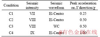
The filtering effects of simulated material and soil vary with the distribution of seismic excitation, which influences the boundary effect. Therefore, two types of seismic excitation waveform of El-Centro and WC (Figure 3) and three types of seismic intensity (i.e., VII, VIII, IX) are selected for the experiment after similar treatment and bandpass filtering of 0.5-50 Hz. X denotes the excitation direction, which is vertical to the artificial boundary. Table 2 shows the specific incentive schemes.
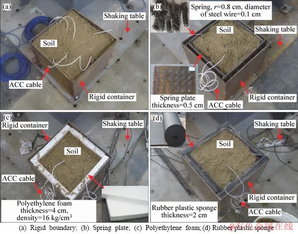
Figure 1 Test containers and boundary materials:
Table 1 Physical properties of boundary materials
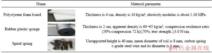
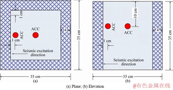
Figure 2 Arrangement scheme of acceleration sensors:
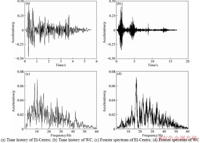
Figure 3 Seismic spectrum after similar transformation and smoothing:
Table 2 Seismic excitation conditions
2.4 Test system
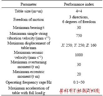
A multifunction shaking table (Figure 4) of Central South University is adopted in this experiment. It consists of a fixed station and two mobile stations. The distance between stations is adjustable from 6 m to 50 m. A single shaker has features of three directions and six degrees of freedom, large stroke, and wide frequency band. Table 3 lists its main performance indexes.
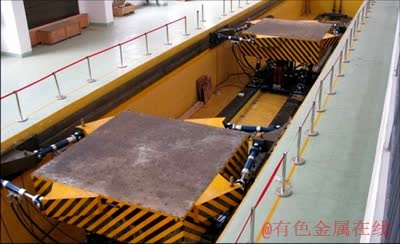
Figure 4 Shaking table system
3 Evaluation method of boundary effect
Early in 1986, WITHMAN and LAMBE [25] indicated that the dynamic response of medium near the container boundary is inconsistent with that of the center due to the boundary effect; however, ideal test results can be achieved by appropriate correction. The ideal boundary conditions of the rigid container are as follows. 1) The model container must be kept at a fixed level during vibration. 2) Complementary shear stress should be provided on the end of the arm and equal to the magnitude of shear stress on soil surface. 3) The quality should be reduced as much as possible to reduce the pressure on the boundary. 4) Horizontal shear stiffness should be zero. 5) The free settlement of soil is unaffected during vibration. Scholars have conducted studies on this issue. LIU et al [12] and MASOUD et al [15] considered the ideal boundary for a dynamic test, in which the acceleration at each point of soil in the model container is consistent. YAN et al [14] and ZHUANG et al [11] also used the similarity of acceleration curves to evaluate the simulation effects of boundary conditions. CHEN et al [2] and CAI et al [26] recommended using the time�Chistory curve, spectrum curve, or relative difference between peak acceleration to reflect the simulation effects of boundary conditions. LOMBARDI et al [16] provided the principle for the selection of the boundary condition of a rigid container for a seismic dynamic test by studying the absorption effect of polyethylene foam board on seismic wave energy.
Table 3 Performance parameters of shaking table
In conclusion, the similarity of acceleration of soil is used as an indicator in the current evaluation method of boundary effect [27-29]. The higher the similarity is, the better the boundary condition will be. To evaluate the boundary effect comprehensively, different rates of peak acceleration, similarity of response spectra, and uneven soil settlements are selected for comprehensive evaluation, as shown as follows:
 (1)
(1)
where �� is the relative deviation of indicators; and X0 and Xi are the quantities of reference and target sensors, respectively. X0 and Xi can be used as the peak acceleration response of soil in different positions in a container, response time history, the spectrum curve of the shaking table and soil in the container, and soil settlements in the container.
4 Test result analysis
4.1 Peak acceleration
The peak acceleration and its difference in the boundary of the container and in the center of soil under four types of boundary condition are calculated. The results are shown in Table 4 and Figure 5.
The results indicate the following.
1) Under different earthquake intensities, such as El-VII excitation, the differential rates of peak acceleration are relatively small when adopting polystyrene foam board and rubber sponge as boundary conditions. The order of differential rate of peak acceleration is as follows: no boundary (16.9%)>spring plate (12.8%)>polystyrene foam (5.1%)>rubber plastic sponge (4.5%). Polyethylene foam and rubber plastic sponge boundaries show a good energy absorption effect and can effectively reduce the boundary effect of a rigid container.
2) When the earthquake intensity of El-VII increases to El-IX, the deviation of peak acceleration under rigid boundary corresponds to a gradually decreasing trend, although its deviation appears to be more than 10%. The deviation of peak acceleration that corresponds to the spring plate boundary decreases considerably. When the seismic intensity reaches to El-IX, the deviation is close to 5%. The deviation of peak acceleration under the polyethylene foam boundary is below 5% and tends to decrease gradually. By contrast, with the increase in seismic intensity, the corresponding acceleration deviation under a sponge boundary gradually increases. The corresponding acceleration deviation increases by 50% if the earthquake intensity increases from El-VII to El-VIII.
3) In comparison with that under the El-Centro wave, the differential rate of peak acceleration of the four types of boundary conditions is increased under the WC wave earthquake excitation, and their boundary effect is obvious. The reason for this result is mainly that the energy distribution of WC wave is more concentrated than that of El wave in the high-frequency section, whereas the surrounding rock has characteristics of low-pass filtering; thus, the dissipation of seismic energy is more obvious when the seismic energy propagates from the boundary to soil mass.
Table 4 Test results of peak acceleration
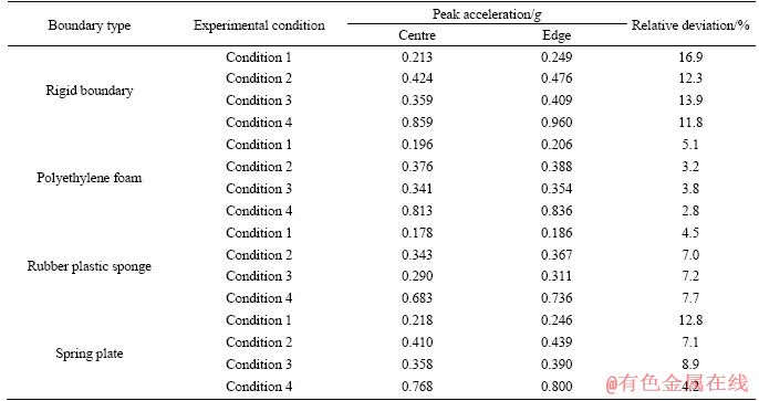
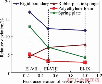
Figure 5 Change laws of relative deviation of peak acceleration and seismic intensity
The preceding analysis indicates that the boundary effect is affected not only by boundary material types but also by the seismic intensity and types of seismic wave. Relatively, the polyethylene foam panel as the boundary material of rigid container has a low boundary effect, and the deviation of peak acceleration can be controlled within 5% at different positions in the test container, whose boundary effect is the most ideal.
4.2 Acceleration time-history spectrum
In the shaking table test, the boundary condition of a rigid container can filter, reflect, and refract the excitation wave to varying degrees, which may change the shape and frequency characteristics of the excitation wave. The closer the boundary effect to reality, the smaller it will be, and the smaller the effect on the wave and frequency characteristics of the excitation wave, the more can the test results reflect the actual situation. The acceleration time-history spectra of soil in the container center are drawn under seismic conditions of El-VIII and WC-8, as shown in Figures 6 and 7, respectively.
The stability of soil response spectrum is poor and the boundary effect is obvious when a rigid boundary condition is adopted. The spring plate boundary has a better simulation effect under the El wave condition, whereas its boundary effect is obvious under WC wave condition. The peak area of the El wave is cut considerably, and the peak area of WC wave appears more concentrated under the sponge boundary. The similarity degree of the dynamic response of soil and its waveform is high under El and WC waves when the foam plate is adopted as a boundary condition, which shows a good simulation effect.
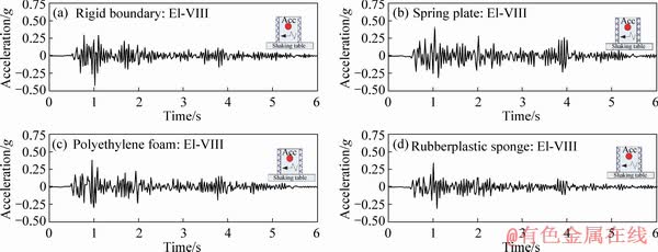
Figure 6 Acceleration-time curve under El-VIII
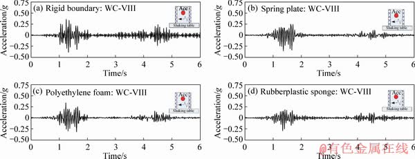
Figure 7 Acceleration-time curve under WC-VIII
4.3 Fourier spectrum
Under ideal boundary conditions, the response spectra of soil appear to amplify or reduce in some frequency bands under earthquake when compared with that caused by excitation from the top of the table, although their overall trend is similar. The smaller the boundary effect is, the more similar the overall trend of the response wave and Fourier spectrum will appear. Fourier transform is applied to the acceleration spectrum of soil in the center of containers with four different boundary conditions under the seismic conditions of El-VIII and WC-VIII degrees; The 0-25 Hz frequency bands, where the energy is concentrated, are extracted (Figures 8 and 9).
The trend of Fourier spectrum varies greatly, and the boundary effect is obvious under rigid boundary conditions. Under the spring plate boundary condition, the Fourier spectrum shows evident variations within the high-frequency band of the El wave while being reasonable under the WC wave. Under the sponge boundary condition, the trend of Fourier spectrum contrasts that under spring plate boundary condition. In comparison with the above, the trend of the Fourier spectrum is more reasonable under both types of excitation when the foam board is adopted and shows better simulation results.
4.4 Uneven soil settlement
Under real earthquakes, the vertical settlement of strata with similar characteristics is roughly uniform within a certain range. However, in the shaking table test, given the limited size of the model container and vertical boundary constraint on soil, the vertical settlement is not uniform; in addition, the more obvious the boundary effect is, the greater the degree of uneven settlement will be. Therefore, the degree of uniformity of soil subsidence can be used as an index in evaluating the effect of different boundary conditions. In this experiment, the surface center of soil is used as the starting point. The post-earthquake settlement is recorded with spacing of 5 cm along the positive and negative directions of earthquake excitation and settlement curves are drawn, as shown in Figure 10. The results show the following.
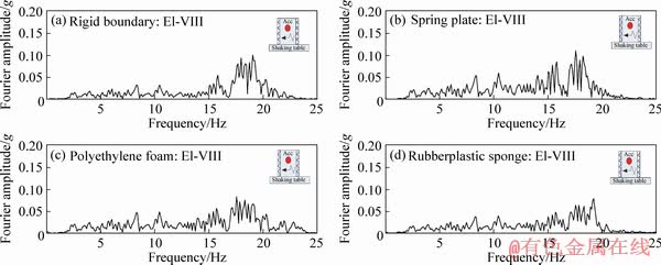
Figure 8 Fourier spectrum under El-VIII
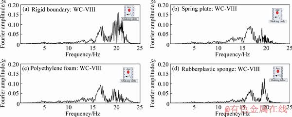
Figure 9 Fourier spectrum under WC-VIII
1) Under the seismic conditions of El-VII and the sponge boundary condition, the soil subsidence is the most uneven, with a maximum differential settlement of 1.3 cm. The maximum differential settlement is 0.9 cm and 0.8 cm respectively under spring plate and polyethylene foam boundary conditions, which show even settlement. Although the soil subsidence is the most even under the rigid boundary condition, its maximum differential settlement is only 0.7 cm. Therefore, the coefficient friction of a sponge is large due to its rough surface, which has a restriction effect on soil. By contrast, the surface of the foam board is smooth and its friction coefficient is small; thus, the vertical restraint on soil is not evident. The deformation of the steel container is extremely small due to its large rigidity. The soil settlement is mainly caused by the action of compaction; thus, it is quite uniform.
2) Although the earthquake intensity increases, the settlement regularity and non-uniformity of soil are similar to that under the seismic conditions of El-VII. The soil settlement is also uniform under the polystyrene foam boundary and rigid boundary conditions.
5 Discussion
5.1 Standards for evaluating boundary effect
At present, the boundary effect of the shaking table test is mostly evaluated by a single index, such as the similarity of acceleration time-history curve or the differential rate of peak acceleration. To a certain extent, this index can assess the boundary effect. However, the experimental results in this study show that the boundary effect is influenced by the seismic wave type, seismic intensity, and the characteristics of the filling medium in the container. The effect is difficult to evaluate only by a single index (e.g., differential rate of peak acceleration). Therefore, using a relatively comprehensive number of indexes (e.g., differential rate of peak acceleration, similarity of time-history and spectrum curves, and uneven settlement of soil in the container) is recommended for evaluating comprehensively its boundary effect.
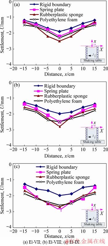
Figure 10 Surface settlement of soil in test container:
5.2 Materials for boundary simulation
In the shaking table test, polystyrene foam board, rubber plastic sponge, and rubber are three common materials for boundary simulation. These materials show great boundary simulation results. The effect of energy absorption is related to the impedance ratio between the boundary material and soil. The larger the impedance ratio is, the better the energy absorption effect and the smaller the boundary effect will be. LOMBARDI et al [16] used three types of foam material to study the energy absorption effect. The authors provided the criterion of selecting the foam board as boundary material, that is, Zf<>s/200, where Zf and Zs are the impedances of foam and soil, respectively; Zs=��sVps, where ��s and Vps are the density and compressional wave velocity of soil, respectively. Meanwhile, some scholars have conducted studies on rubber materials. The reasonable addition of rubber layers along the vibration direction can effectively reduce the boundary effect. Generally, a rubber material with an elastic modulus of 2.5 times that of the container is adopted [30].
5.3 Thickness of boundary material
Rational selection should be conducted for both types of materials and their thicknesses to achieve an ideal boundary condition. Studies show that the shear deformation of free-field soil occurs under the action of an earthquake, thereby resulting in shear beam deformation. However, the deformation at the boundary varies with the types and the boundary conditions of a model container. Only when the deformation of the container is in accordance with that of soil at the boundary would the interaction between them be reduced, thereby resulting in the reduction of the ��model container effect.�� LOMBARDI et al [16] studied foam board and indicated that the minimum thickness of foam plate material as boundary should satisfy tkmin<>max/��y, where tkmin is the minimum thickness of the absorbing material, ��y is the deformation of absorbing material at the yield point, and umax is the value of the maximum horizontal displacement expected within soil mass and should be estimated numerically. The thickness of materials as the boundary is at least 5tkmin in practical applications.
6 Conclusions
In a dynamic test of soil structure, the boundary effect of the rigid container directly affects the results. In this study, four types of typical boundary are established, and different seismic intensities and seismic wave types are considered. On the basis of the test results, the simulation results of different boundary conditions are analyzed from four aspects, that is, the differential rate of peak acceleration, the acceleration time-history spectrum, the curve of spectral response, and the uneven soil settlement in the rigid container. The results imply the following.
1) In comparison with that of the other three boundary conditions, the differential rate of peak acceleration between the sample and reference points in the container and the uneven settlement of soil in the container are relatively small under the polystyrene foam boundary condition. The curves of acceleration and spectrum are considerably similar to the waveform of excitation from the shaking table. Therefore, the polystyrene foam boundary effect is the smallest, and its simulation effect is the most ideal.
2) When earthquake intensity is low, rubber sponge as the boundary condition can also reduce the boundary effect. However, with the increase in earthquake intensity, the boundary effect increases gradually due to its low elastic modulus, relatively rough surface, and large friction coefficient, thereby affecting the test results.
3) In comparison with that under the El-Centro wave, the differential rate of peak acceleration of the four types of boundary condition under the WC wave earthquake excitation is increased, and their boundary effect is obvious. This occurrence is mainly caused by the energy distribution of the WC wave being more concentrated than that of the El wave in the high-frequency band, whereas the surrounding rock has characteristics of low-pass filtering; thus, its dissipation of seismic energy is more obvious when the seismic energy propagates from the boundary to soil mass. The boundary effect is affected not only by the type of artificial boundary material but also by the seismic wave type, earthquake intensity, and the filling medium in the container.
References
[1] JIANG L Z, CHEN J, LI J. Seismic response of underground utility tunnels: Shaking table testing and FEM analysis [J]. Earthquake Engineering and Engineering Vibration, 2010, 9: 555-567. DOI:10.1007/s11803-010-0037-x.
[2] CHEN G X, WANG Z H, ZUO X, DU X L, GAO H M. Shaking table test on the seismic failure characteristics of a subway station structure on liquefiable ground [J]. Earthquake Engineering & Structural Dynamics, 2013, 42: 1489-1507. DOI:10.1002/eqe.2283.
[3] CHEN Z Y, LI Y Y. Boundary deformation of model container design [J]. Earthquake Resistant Engineering and Retrofitting, 2015, 37(5): 106-112. DOI: 10.16226/j.issn. 1002-8412.2015.05.018.
[4] KHERADI H, YUKIHIRO M, RYOSUKE O, FENG Z. 3D dynamic finite element analyses and 1g shaking table tests on seismic performance of existing group-pile foundation in partially improved grounds under dry condition [J]. Soil Dynamics and Earthquake Engineering, 2016, 90: 196-210. DOI:10.10 16/j.soildyn.2016.08.032.
[5] LI Y D, CUI J, GUAN T D, JING L P. Investigation into dynamic response of regional sites to seismic waves using shaking table testing [J]. Earthquake Engineering and Engineering Vibration, 2015, 14(3): 411-421. DOI:10.1007/ s11803-015-0033-2.
[6] PANOS K, ANNA S D S, AUGUSTO P, MATTHEW D, ALDO E, ARMANDO L S, COLIN T, GEORGE M. Investigation of seismic response of cantilever retaining walls: Limit analysis vs shaking table testing [J]. Soil Dynamics and Earthquake Engineering, 2015, 77: 432-445. DOI:10.1016/j.soildyn.201 5.05.018.
[7] YANG G, YU T, YANG X, HAN B. Seismic resistant effects of composite reinforcement on rockfill dams based on shaking table tests [J]. Journal of Earthquake Engineering, 2017, 21(6): 1010-1022. DOI: 10.1080/13632469.2016. 1190800.
[8] WANG J X, YANG G, LIU H L, SANJAY S N, TANG X J, XIAO Y. Seismic response of concrete-rockfill combination dam using large-scale shaking table tests [J]. Soil Dynamics and Earthquake Engineering, 2017, 99: 9-19. DOI: 10.1016/ j.soil dyn.2017.04.015.
[9] SRILATHA N, MADHAVI L G, PUTTAPPA C G. Effect of frequency on seismic response of reinforced soil slopes in shaking table tests [J]. Geotextiles andGeomembranes, 2013, 36: 27-32. DOI:10.1016/j.geotexmem.2012.10.004.
[10] TANG L, CONG S Y, LING X Z, JU N P. The boundary conditions for simulations of a shake-table experiment on the seismic response of 3D slope [J]. Earthquake Engineering and Engineering Vibration, 2017, 16: 23-32. DOI:10.1007/ s11803-016-0363-8.
[11] ZHUANG Y Z, CHEN Y, CHEN B, WANG S Z, HAN Y T. Shaking table test on boundary effect of steel box for pile-soil interaction research [J]. Journal of Fuzhou University (Natural Science Edition), 2016, 44(4): 504-509. http://en.cnki.com.cn/Article_en/CJFDTOTAL-FZDZ201604009.htm. (in Chinese)
[12] LIU H X, XU Q, LI Y R. Effect of lithology and structure on seismic response of steep slope in a shaking table test [J]. Journal of Mountain Science, 2014, 11(2): 371-383. DOI:10.1007/s11629-013-2790-6.
[13] MAJID Y. Investigation on the seismic performance of steel-strip reinforced-soil retaining walls using shaking table test [J]. Soil Dynamics and Earthquake Engineering, 2017, 97: 216-232. DOI:10.1016/j.soildyn.2017.03.011.
[14] YAN X, YUAN J Y, YU H T, BOBET A, YUAN Y. Multi- point shaking table test design for long tunnels under non- uniform seismic loading [J]. Tunnelling and Underground Space Technology, 2016, 59: 114-126. DOI: 10.1016/ j.tust.2016.07.002.
[15] MASOUD R M, MOHAMMAD H B. Seismic ground motion amplification pattern induced by a subway tunnel: Shaking table testing and numerical simulation [J]. Soil Dynamics and Earthquake Engineering, 2016, 83: 81-97. DOI:10.1016/j.soildyn.2016.01.002.
[16] LOMBARDI D, BHATTACHARYA S, SCARPA F, BIANCHI M. Dynamic response of a geotechnical rigid model container with absorbing boundaries [J]. Soil Dynamics and Earthquake Engineering, 2015, 69: 46-56. DOI:10.1016/j.soildyn.2014. 09.008.
[17] LEI M F, LIN D Y, HUANG Q Y, SHI C H, HUANG L C. Research on the construction risk control technology of shield tunnel underneath an operational railway in sand pebble formation: A case study [J]. European Journal of Environmental and Civil Engineering, 2018, 22(s1): 1-15. DOI: 10.1080/19648189. 2018 1475305.
[18] LEI M F, LIN D Y, SHI C H, MA J J, YANG W C. A structural calculation model of shield tunnel segment: Heterogeneous equivalent beam model [J]. Advances in Civil Engineering, 2018: 9637838. DOI: 10.1155/2018/9637838.
[19] BATHURST RJ, HATAMI K. Seismic response analysis of a geosynthetic reinforced soil retaining wall [J]. Geosynthetics International, 1998, 5(1, 2): 127-166. DOI: 10.1680/gein.5.01 17.
[20] BHATTACHARYA S, LOMBARDI D, DIHORU L, DIETZ M, CREWE A J, TAYLOR C A. Model container design for soil-structure interaction studies [J]. Role of Seismic Testing Facilities in Performance-Based Earthquake Engineering, 2011, 22: 135-158. DOI:10.1007/978-94-007-1977-4_8.
[21] LIN Y L, LENG W M, YANG G L, LI L, YANG J S. Seismic response of embankment slopes with different reinforcing measures in shaking table tests [J]. Natural Hazards, 2015, 76: 791-810. DOI: 10.1007/s11069-014- 1517-5.
[22] LIN Y L, YANG G L. Dynamic behavior of railway embankment slope subjected to seismic excitation [J]. Natural Hazards, 2013, 69(1): 219-235. DOI:10.1007/s110 69-013-0701-3.
[23] LEI M F, LIN D Y, YANG W C, SHI C H, PENG L M, HUANG J. Model test to investigate failure mechanism and loading characteristics of shallow-bias tunnels with small clear distance [J]. Journal of Central South University, 2016, 23(12): 3312-3321. DOI: 10. 1007/s11771-016-3397-1.
[24] XU H, LI T B, XIA L,ZHAO J C, WANG D. Shaking table tests on seismic measures of a model mountain tunnel [J]. Tunnelling and Underground Space Technology, 2016, 60: 197-209. DOI:10.1016/j.tust.2016.09.004.
[25] WHITMAN R V, LAMBE P C. Effect of boundary conditions upon centrifuge experiments using ground motions simulations [J]. GeotechnicalTestingJournal, 1986, 9: 61-71. DOI��10.1520/GTJ11031J.
[26] CAI L W, GU Y, ZHUO W D, ZHUANG S M. The boundary effects of shaking table test soil box based on finite element simulation [C]// National Conference on Structural Engineering. Lanzhou, China, 2014. http://cpfd.cnki.com.cn/ Article/CPFDT OT AL-LXFY201410002060.htm.
[27] LEI M F, LIU J Y, LIN Y X, SHI C H, LIU C. Deformation characteristics and influence factors of a shallow tunnel excavated in soft clay with high plasticity [J]. Advances in Civil Engineering, 2019: 7483628. DOI: 10.1155/2019/ 7483628.
[28] LEI M F, LIU L H, LIN Y X, LI J. Study on flexural bearing capacity calculation method of enclosure pile with partial excision in deep foundation pit [J]. Advances in Civil Engineering, 2019: 4812857. DOI: 10.1155/2019/4812857.
[29] LIN Y X, PENG L M, LEI M F, YANG W C, LIU J W. Mechanical properties of bimrocks with high rock block proportion [J]. Journal of Central South University, 2019, 26(12): 3397-3409. DOI: 10.1007/s11771-019-4262-9.
[30] LOU M L, WANG W J, ZHU T, MA H C. Soil lateral boundary effect in shaking table model test of soil-structure system [J]. Earth Quake Engineering and Engineering Vibration, 2000, 20(4): 30-36. DOI: 10.13197/j.eeev.2000. 04.005. (in Chinese)
(Edited by HE Yun-bin)
���ĵ���
��̨�����и���ģ�����˹�����߽�ĺ�����������о�
ժҪ�����ø�������������ȵ��¹��̽ṹ�����������о�ʱ�������ı߽������ǹ�ϵ��������ȷ�Ĺؼ�����֮һ���ر��������������ֱ���˹�����߽硣�����ڴ��������еĻ����ϣ��������ֵ��ͱ߽磬�����ǵ����ҶȺ͵������ͣ��ֱ�չ����̨���顣�������������������ֱ�Ӽ��ٶȷ�ֵƫ����ٶ�ʱ������ҶƵ���������Լ���������������治���ȳ����ĸ���������ֱ߽��ģ��Ч�����������۷����������������̨�����У��߽�ЧӦ�Ĵ�С�������ܱ߽�������ʵ�Ӱ�죬��������Ҷȡ����������Լ��������������ʵ��˲������йأ�������������ֱ߽磬����ϩ��ĭ��߽�ģ��Ч����Ϊ���룬�����ŵ����Ҷȵ�������߽�ЧӦ����С�����ơ����ϼ����о����ϣ�����̨�����еı߽�ЧӦ���۱����߽�������ͼ���ȵ�ȷ���������������ܽᣬ��������Ӧ����Ʒ����ͽ��顣
�ؼ��ʣ���̨���飻�˹�����߽磻����ģ����
Foundation item: Projects(51978669, U1734208) supported by the National Natural Science Foundation of China; Project(2018JJ3657) supported by the Natural Science Foundation of Hunan Province, China
Received date: 2018-07-01; Accepted date: 2019-09-05
Corresponding author: LIN Yue-xiang, PhD; Tel: +86-15111008697; E-mail: csulyx2010@csu.edu.cn; ORCID: 0000-0003-4730-387X
Abstract: When conducting dynamic tests of underground structure by a rigid container, reasonable boundary conditions are one of the essential factors related to the accuracy of test results, especially the artificial boundary perpendicular to the excitation direction. On the basis of numerous studies, shaking table tests with four different typical boundaries are performed in this study. The tests consider the seismic intensity and seismic wave types. Then, the simulation effects of the four boundary conditions are evaluated from four aspects as follows: the differential rate of peak acceleration, acceleration curve, similarity of Fourier frequency spectra, and uneven soil settlement in rigid containers. Results show that the simulation effects of the boundary conditions are not only affected by the nature of the boundary material but also related to the seismic intensity, types of seismic waves, and filter characteristic of the filling medium in containers. In comparison with the other three types of boundary condition, foamed polyethylene shows the best simulation effect and its effect decreases gradually with the increase in earthquake intensity. Finally, on the basis of existing studies, the evaluation criteria of boundary effect, the principle for the selection of boundary material type and the thickness of boundary material are discussed and summarized, and the corresponding design methods and suggestions are then provided.
