
J. Cent. South Univ. (2017) 24: 2504-2512
DOI: https://doi.org/10.1007/s11771-017-3663-x

Heading control method and experiments for an unmanned wave glider
LIAO Yu-lei(������), LI Yi-ming(��һ��), WANG Lei-feng(���ڷ�), LI Ye(����), JIANG Quan-quan(��ȨȨ)
Science and Technology on Underwater Vehicle Laboratory, Harbin Engineering University, Harbin 150001, China
 Central South University Press and Springer-Verlag GmbH Germany, part of Springer Nature 2017
Abstract:
The control system designing of unmanned wave glider (UWG) is challenging since the control system is weak maneuvering, large time-lag and large disturbance, which is difficult to establish accurate mathematical model. The control system for the ��Ocean Rambler�� UWG is studied in this work. A heading control method based on S-surface controller is designed. For the ��rudder zero drift�� problem in trials, an improved S-surface control method based on rudder angle compensation is proposed, which can compensate the adverse effects from environmental forces and installation error. The tank test and sea trial results prove that the proposed control method has favorable control performance, and the feasibility and reliability of the designed control system are also verified.
Key words:
unmanned wave glider; heading control; S-surface control; control system��
1 Introduction
Traditional motion monitoring platforms(research vessel, unmanned surface vehicle, underwater vehicle etc.) take fuel oil or battery as power sources and the endurance is limited by energy capacity. It consumes lots of time, costs a lot and may also bring pollution to the environment. However, there are abundant green energy resources in the oceans. In recent years, more and more researchers pay attention to take ocean energy as the power sources of ocean vehicles. There have been many researches on ocean energy powered unmanned vehicles [1], mainly about solar powered underwater vehicle [2], thermal powered underwater vehicle [3], wind powered or solar powered unmanned surface vehicle [4, 5],and wave powered vehicle .
Unmanned wave glider is a new kind of wave powered unmanned ocean vehicle. UWG has many outstanding advantages like infinite endurance, autonomy, zero discharge, low cost. And UWG can perform a wide range of tasks such as ocean environment monitoring, weather forecast, biological investigation, communication relay, distant early-warning in long time scale and large spatial scale autonomously. UWG has broad application foreground in military and civil fields, and is widely applied in marine scientific research and survey [6�C10]. In recent ten years, UWG becomes a hotspot in the world.
The intelligent control system is the most important part for UWG. A control system with good control performance and intelligence level is a precondition for UWG in application. The thrust of UWG comes from wave motion and changes randomly with sea condition. It means that the thrust is random and uncontrollable, and the speed is uncontrollable. Only the rudder system is controllable. The UWG control problem is a special kind of weak maneuvering (underactuated) control problem. The Liquid Robotics Co. has achieved remote autonomous control of UWG, but there is no technical details about the control system and control algorithm.
In 2012, KRAUS et al [11] established the maneuverability mathematical model based on ��SV2�� UWG created by the Liquid Robotics Co. PID control algorithm was applied in UWG station keeping control and the mathematical simulation without current was carried out. The results show that the UWG��s station keeping radius is less than 40 m and there is a dead zone of 10 m radius. Obviously, due to the weak maneuvering property, it is difficult for UWG to realize the same control precision as traditional ocean unmanned vehicles.
In 2014, ZHANG et al [12] developed a shore-based monitoring application program for UWG under Visual Studio C#.net development suite. GPS/Beidou dual- mode technology and Google earth COM API were adopted in the application program. The application program can realize GPS positioning, satellite data transmission, vector map based track displaying, trajectory presetting, environment monitoring data storage and classification, visual checking and querying of working status, etc. The trial results show that the shore-based monitoring system basically completed the instruction sending and trajectory tracking tasks.
In the same year, SHI et al [13] mainly discussed the motion control problem of UWG. A LPC2478-based embedded control system was designed. Based on Gaussian geodesic algorithm and PID control algorithm, the navigation strategy was constituted and achieved visual tracking and virtual anchor of UWG. Meanwhile, to ensure the accuracy of navigation information, two groups of sensors (wave height meter and flow meter) were added as auxiliary navigation. A complete navigation system was constructed and sea trials were conducted.
In 2015, LU et al [14] focused on the ��Ocean Rambler�� UWG. Considering about the nonlinear, time-variable, uncertain properties, a fuzzy adaptive PID algorithm was put forward combining PID control with fuzzy control.Simulation experiments show that the fuzzy PID controller has the advantages of small overshoot and short adjustment time compared with PID controller. And the station keeping simulation experiment was carried out.
In this work, we will first introduce the ��Ocean Rambler�� UWG and design the UWG motion control system. Then, for the characteristics of difficult modeling and large disturbance, we discuss a heading control method based on S-surface controller, and propose an improved S-surface control method based on rudder angle compensation. Finally, the feasibility and reliability of the proposed control method are verified by tank tests and sea trials.
2 Control system design
We will start with a general description of ��Ocean Rambler�� UWG before discussing the control system in detail.
2.1 ��Ocean rambler�� UWG
Since 2012, the Harbin Engineering University Science and Technology on Underwater Vehicle Laboratory has carried out research on UWG firstly in China. Two types of prototypes ��Ocean Rambler I�� and ��Ocean Rambler II�� (Fig. 1) have been made. Several standard tank tests and sea trials have been completed.
The UWG consists of a surface float (Float), a submerged glider (Wave thruster, or Glider) and a flexible umbilical. Several wings are hinged on the glider. Glider provides thrust for UWG. In wave environment, when the float moves down a wave, the glider falls under its own weight, and the aft of wings rises; conversely, when the float is pulled upward by a wave, the umbilical lifts the glider and the aft of wings falls. The wings fall and rise alternately like a fish that push the glider forward, and the float is pulled forward by umbilical. The operating principle is shown in Fig. 1. The UWG mechanically converts the wave energy to the thrust, and other motive powers are unnecessary.
This work focuses on the ��Ocean Rambler�� UWG. The UWG can sail and work autonomously and separately. Besides, the UWG can be a member of UWG formation which can realize multiprocessor control like multi-UWG navigation and teamwork. As shown in Fig. 2, the UWG consists of the float, propelling and maneuvering, motion control, energy, remote monitoring, wireless communication, navigation, environment monitoring, and status monitoring subsystems divided by functionality. The motion control subsystem is the core of the UWG and will be mainly concerned in this work.
2.2 Motion control system design
The motion control system of UWG consists of embedded computer system (hardware) and embedded control system (software). The core of embedded computer system is a development board based on Atmel industrial processor (embedded arm computer system). The development board highly integrated ARM9 core of 400 MHz and provide abundant peripheral interfaces: ADC, CAN, serial port, Ethernet, USB, GPIO, PWM,SDIO, voice interface, audio signal interface, video signal interface, TF card interface etc. Compared to other X86 embedded computer system like PC/104, industrial ARM computer guarantees the reliability and environmental suitability in long-time running and reduces the power consumption. Figure 3 shows the hardware architecture of UWG control system.
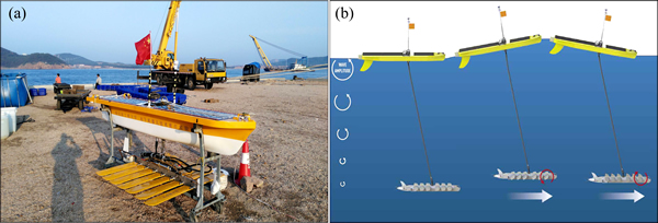
Fig. 1 ��Ocean Rambler�� UWG (a) and operating principle (b)
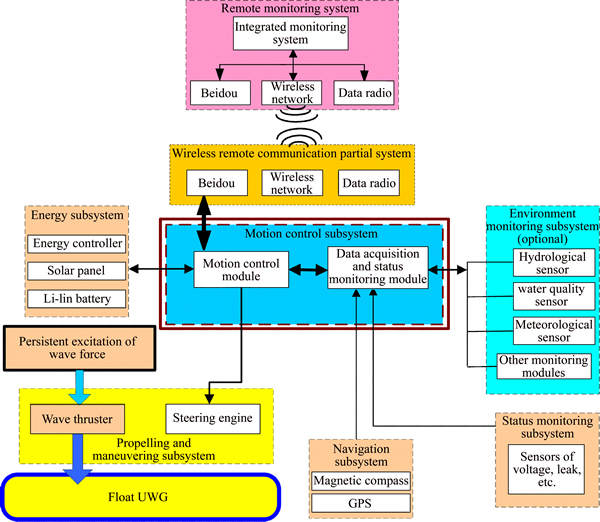
Fig. 2 System composition of UWG
Considering the expandability and cost, we choose the open source multiple task operating system Linux in embedded ARM computer. Linux is stable, tailorable and convenient to develop and use, it is widely used in many fields like communication system, industrial control, aerospace, consumer electronics etc. Shore-based monitoring system is developed using Matlab GUI under Windows. By wireless communication system, the shore- based monitoring computer can monitor the working condition of UWG remotely at real time. Besides, network debugging and monitoring interface are reserved.
Motion control problems mainly include: heading control, way-point following, station keeping control etc. The heading control is the foundation of the other subjects. We will focus on the heading control method of the UWG.
3 Heading control method
3.1 S-surface controller
The heading control problem of UWG is difficult: 1) UWG is drove by wave power, and the practices have proven that UWG is a weak maneuvering system moving at a low speed (about 0.5�C2 kn) whose heading control ability is poor; 2) UWG consists of float, glider and flexible umbilical, and the rudder system is installed on the glider, thus the UWG system has great inertia, great lag and likely to shock; 3) small size of UWG causes that UWG is severely disrupted by environmental forces on seas, which means that UWG system is in large disturbance and poor heading keeping ability.
In a word, the UWG system is weak maneuvering, large time-lag, and large disturbance, which is difficult to establish accurate mathematical model. And the designed controller must satisfy the characteristics of UWG. Besides, the designed controller must be robust to complex environmental forces.
Intelligent control combines control theory and artificial intelligence technology (AIT) together flexibly, and can be applied on complex and uncertain controlled members. Optional intelligent control methods include neural network, fuzzy logic control, expert control, etc. In this work, we choose S-surface controller [15]. S-surface controller combines the fuzzy control theory and simple PID control structure together and is widely used in control of underwater vehicle, USV etc [15�C18].
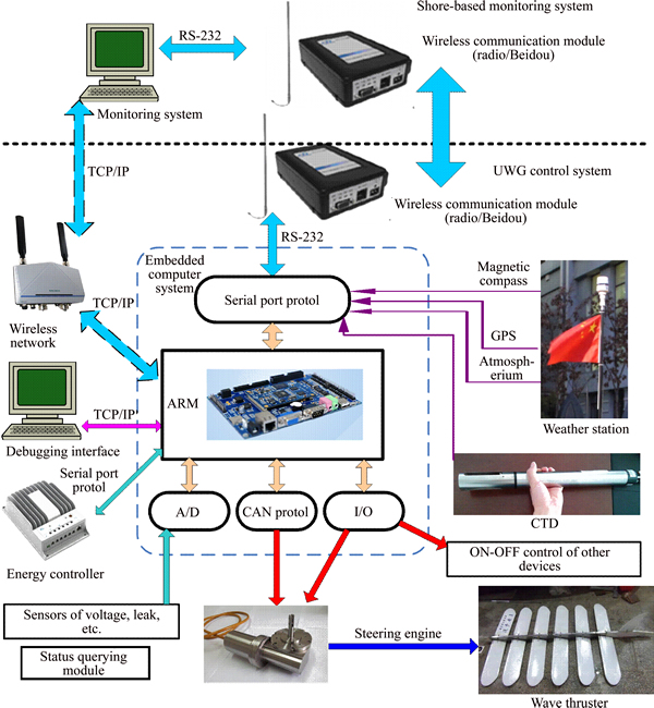
Fig. 3 Hardware architecture of UWG control system
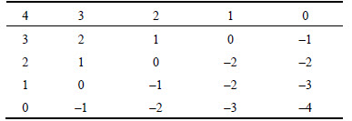
Description of S-surface controller is as follows: take the numerical values from the principle diagonal of fuzzy controller control rule table (Table 1) and then link to a fold line. The fold line can be fitted as a smooth curve (like tanh function, Sigmoid function etc.). Actually the smooth curve can be seen as a fold line with innumerable pieces while the length of each piece tends to zero. Obviously, the fold line surface that corresponds to the whole fuzzy control law library can be fitted by a smooth curved surface.
Table 1 Control rule table
The Sigmoid curve function can be expressed as
 (1)
(1)
Then, the Sigmoid curved surface function is
 (2)
(2)
We choose the control model of the S-surface controller as
 (3)
(3)
where e and  are control inputs (normalized error and error rate, respectively); u is the normalized control force output; k1 and k2 are the control parameters corresponding to error and error rate respectively, and can influence the rate of change of corresponding control inputs. The three-dimensional smooth curved surface in Fig. 4 shows the relationship between error, error rate and control force. Compared with PID controller, the structure of S-surface controller is similar to the structure of PD controller, but PD controller is linear and S-surface controller is nonlinear. Commonly, using a nonlinear function to fit nonlinear system is more accurate than using a linear function [18].
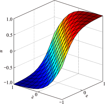
Fig. 4 Sigmoid curved surface
In this work, the control output is the rudder angle, and the control inputs are heading error and angular velocity of yaw. By adjusting ki1 and ki2, the share of error and error rate in control output can be changed. In other words, the control characteristics like overshoot and rate of convergence can be changed to meet the control demands by adjusting ki1 and ki2. The usual control parameters adjusting laws: if the overshoot is large, decrease ki1 and increase ki2; otherwise, if the system converges slowly, increase ki1 and decrease ki2.
3.2 Improved S-surface control method based on rudder angle compensation
We found two main problems in the heading control trials:
1) ��Rudder zero drift�� problem
In order to sail along a straight line, a nonzero rudder angle  is needed but not a persistent zero rudder angle ��0. The nonzero rudder angle is the rudder zero drift
  which is caused by: a) Disturbance of environmental forces. The disturbance of wind, wave, current and other unknown environmental forces causes a heading torque on the UWG. The heading torque needs to be compensated by a nonzero rudder angle by which the UWG can keep a straight line. The heading torque is time-varying and uncertain, so the compensating rudder angle is time-varying and needs to be online estimated.b) The installation site of the umbilical can not be the very accurate expected position, so there is a deflection angle between the centre line of thrust from the glider and the longitudinal section in center plane of the float.c) Other factors such as the error of rudder system.
The above-mentioned factors exist simultaneously and can not be analyzed independently. The factors combine to produce the result of ��rudder zero drift��. The ��rudder zero drift�� problem makes the heading control more difficult. It influences the accuracy of heading control deeply. Under disadvantages the UWG may not keep the heading. The trial results show that even the commonly used S-surface control method with integral part still can not solve the ��rudder zero drift�� problem very well.
2) Time-lag problem
In trials, we found that if we set the rudder angle threshold ��c,max��40�� in heading control, it easily causes shock which is hard to converge and even lead to divergence. Under large control rudder angle, the time lag of the steering engine and the UWG severely impacts the control performance. We also found that the above-mentioned problem can not be easily solved by adjusting control parameters. Accordingly, we proposed an improved S-surface control method based on rudder angle (actuator) compensation.
Considering about the captain��s steering experience in heading control: when sailing in complex oceanic experiment, the captain can learn and summarize the steering laws, then adjusting the rudder angle to compensate the adverse impact of ��rudder zero drift�� based on rich experience. The adjusting process is called rudder angle compensation. Using the thought of the captain for reference, we combine the expert control and S-surface control together and propose an improved S-surface control method based on rudder angle compensation (Fig. 5).
The specific improvement approaches:
1) Dynamically revising the zero point of rudder angle. There is a basic steering fact that under a persistent left rudder ��>0, the float will turn left and the turning angular velocity r>0. Even if considering about the time-lag of the system, under a left rudder r>0 for a period of time T��, the ship should turn left. If the float does not turn left or even turn right, we could believe that the zero point of the rudder has drifted and needs to be compensated.
 (4)
(4)
where  is the maximal revising rudder angle; T�� is the retardation time; t is the duration in one steering condition;
  is the adjusting factor of revising rudder angle.
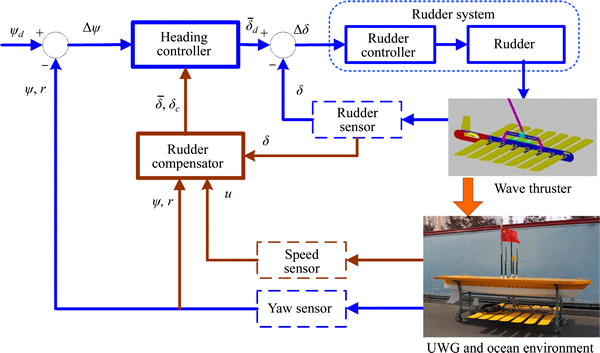
Fig. 5 Principle of improved heading control
2) Dynamically adjusting the control rudder angle. Because of the special multi-linkage structure, a large rudder angle may cause the glider to turn much faster than the float and umbilical twines, thus the heading of system may shock or even diverge. Small rudder angle can reduce the time-lag from the rudder system and the multi-linkage structure. In order to save energy, small rudder angle is preferred. The specific adjusting rule is that the control rudder ��c decreases when the speed increases.
 (5)
(5)
where  are the maximal and minimum control rudder angles respectively; u is the speed (kn); ��c(u) is control rudder angle under velocity u; ���� is the adjusting factor of control rudder angle. The parameters in following trials are
  T��=5 s,
 ��c,max=35��, ��c,max=25��, ����=2.
4 Trial results and analysis
In 2014�C2015, ��Ocean Rambler�� UWG completed system joint debugging, tank tests, sea trials in Harbin Engineering University general deep water tank and Weihai coastal waters respectively. Main trial subjects include: remote controlled sailing trial, motion control trial, etc. Part of the trial results and analysis are shown below:
4.1 Tank test results and analysis
In the heading control trials in tank, we used two kinds of S-surface method for comparison.
1) The wave generator generated the wave of 0.23 m wave height and 10 m wave length in the tank. The control threshold value of rudder angle was ��35��, and after trying for several times we set the control parameters k1=40, k2=0.3. The rudder angle compensation was not introduced in the tank test.Figure 8 shows the heading angle control result of one of the trials that the initial heading angle was �C54�� and the target heading angle was set as �C83��.
From Fig. 8, the heading responses quickly and smoothly. There is little overshoot and no shock in the ascent stage. It proves that the control performance of S-surface controller is pretty good. But the heading angle has not converged to the desired heading angle and the steady-state error is about 5��. It is because of the effect of wave force on UWG when heading waves and the time-lag from the multi-linkage structure of UWG. Next, the rudder angle compensation will be introduced in the tank test.
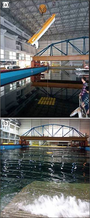
Fig. 6 Tank tests of ��ocean rambler�� UWG

Fig. 7 Sea trials of ��Ocean Rambler�� UWG
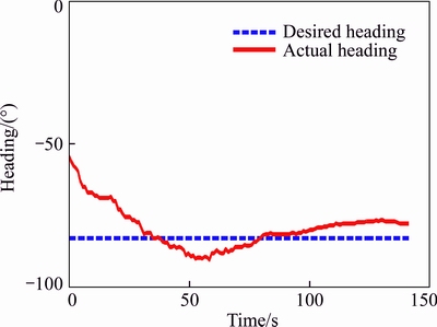
Fig. 8 Heading response curve in heading control trial
2) The wave parameters and control parameters were same as that in above-mentioned tank test. The improved S-surface control method based on rudder angle compensation was applied. Figure 9 shows the heading angle control result of one of the trials that the initial heading angle was �C50�� and the target heading angle was set as �C83��.
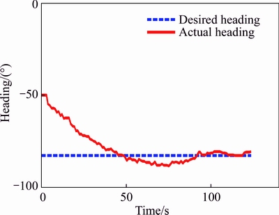
Fig. 9 Heading response curve in heading control trial
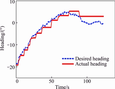
Fig. 10 Rudder angle response curve in heading control trial
Multiple times heading control trial results show that the heading angle output is almost no overshoot and shock, but it responses slowly (about 50 s). It is because of bad steerage caused by low speed (about 0.6�C1.0 knots). The heading control accuracy is about ��3��. The heading keeping control was completed with the rudder operating only about ten times, which means that the energy consumption was reduced by the control method. The trial results prove that under the disturbance of environmental forces, the UWG still has relatively strong heading keeping ability which builds the foundation for UWG autonomous control and autonomous working.
4.2 Sea trial results and analysis
In sea trials, the control method and parameters were same with the one in Section 3.1. We carried out the heading control trials in SS1 to SS3. The typical trial results are shown in Figs. 11 and 12.
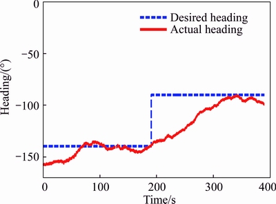
Fig. 11 Heading response curve in heading control trial (SS2)
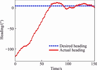
Fig. 12 Heading response curve in heading control trial (SS3)
From Figs. 11 and 12, the UWG has good heading control performance in ocean environment and the control accuracy is ��8��. From the comparison between Figs. 11 and 12, with the increasing of sea condition, the heading stabilizing time decreases. Because the larger sailing speeds in high sea state improve the steerage and turning ability. From the comparison between Figs. 10 and 11, although the sea condition in the tank (SS1) is lower than that on the sea (SS2), the heading control performance is better. It is because the environmental disturbance of wind, current and breaking wave is weaker in tank than that in sea.
5 Conclusions
The UWG control system worked steadily in the tank test and sea trial process, which proves the reliability and rationality of the UWG control system in respects of architecture, control algorithm, data processing, hardware and software. Multiple subjects were completed and the designed control system achieved the heading control and way-point following control missions. The trial results prove that the improved S-surface control method meets the requirement of precision on motion control and has a good dynamic performance.
Only the sea trials in low sea condition were completed. The future work will focus on: combining the intelligent control theory, adaptive theory and S-surface control method together to improve the control performance and adaptive ability in rough marine environment; it is necessary to carry out large-scale sea trials including autonomous path following and autonomous environment monitoring in high sea states.
References
[1] WANG Xiao-ming, SHANG Jian-zhong, LUO Zi-rong. TANG Li, ZHANG Xiang-po, LI Juan. Reviews of power systems and environmental energy conversion for unmanned underwater vehicles [J]. Renewable and Sustainable Energy Reviews, 2012, 16(2): 1958�C1969.
[2] CRIMMINS D M, PATTY C T, BELIARD M A, BAKER J, JALBERT J C, KOMERSKA R J, CHAPPELL S G, BLIDBERG D R. Long-endurance trial results of the solar-powered AUV system [C]// Proceeding of the 2006 IEEE/MTS Oceans. Boston, USA: IEEE, 2006: 1�C5.
[3] WANG X, LI H, GU L. Economic and environmental benefits of ocean thermal energy conversion [J]. Mar Sci, 2008, 32(11): 84�C87.
[4] MANLEY J E. Autonomous surface vessels, 15 years of development [C]// Proceeding of Oceans 2008 MTS/IEEE Quebec Conference and Exhibition (Ocean��08). Quebec, Canada, IEEE, 2008: 1�C4.
[5] BIBULI M, BRUZZONE G, CACCIA M. Line following guidance control: Application to the Charlie unmanned surface vehicle [C]// Proceedings of the 2008 IEEE/RSJ International Conference on Intelligent Robots and Systems. Nice, France: IEEE, 2008: 3641�C3646.
[6] MANLEY J, WILLCOX S. The wave glider: A new concept for deploying ocean instrumentation [J]. IEEE Instrumentation & Measurement Magazine, 2010, 13(6): 8�C13.
[7] MEYER-GUTBROD E, GREENE C H, PACKER A, DORN H. Long term autonomous fisheries survey utilizing active acoustics [C]// Proceeding of the 2012 IEEE/MTS Oceans. Hawaii, USA: IEEE, 2012: 1�C5.
[8] FRANCOIS G, GILLES H, RYAN C. Wave Gliding for marine litter [J]. Rapp Comm Int Mer M��dit, 2013, 40: 306.
[9] KATHRYN H, WANG Q, LIND R J, YAMAGUCHI R T, KALOGIROS J. Autonomous Wave Gliders for air-sea interaction research [C]// Proceedings of the 19th Conference on Air-Sea Interaction. Phoenix, USA, 2015: 13.5.
[10] XU Chun-ying, CHEN Jiang-wang, ZHENG Bing-huan. Research status and applications of wave glider [J]. Journal of Ocean Technology, 2014, 33(2): 111�C112. (in Chinese)
[11] KRAUS N D. Wave glider dynamic modeling, parameter identification and simulation [D]. Hawaii: University of Hawaii, 2012: 27�C74.
[12] ZHANG Sen, SHI Jian, ZHANG Xuan-ming, JIA Li-juan, QIN Yu-feng, QI Zhan-feng, YANG Yan, SUN Xiu-jun. Design of the shore-based monitoring system for wave gliders [J]. Journal of Ocean Technology, 2014, 33(3): 119�C124. (in Chinese)
[13] SHI Jian, GONG Wei, QI Zhan-feng, JIA Li-juan, ZHANG Sen, QING Yu-feng. Research of wave glider navigation control strategy based on multi-sensor [J]. Transducer and Microsystem Technologies, 2014, 33(6): 23�C30. (in Chinese)
[14] LU Xu. Research on the general technology of wave glider [D]. Harbin: Harbin Engineering University, 2015: 23�C56. (in Chinese)
[15] LIU Xue-min, XU Yu-ru. S control of automatic underwater vehicles [J]. Ocean Engineering, 2001, 19(3): 81�C84. (in Chinese)
[16] LIU Jian-cheng, YU Hua-nan, XU Yu-ru. Improved s plane control algorithm for underwater vehicles [J]. Journal of Harbin Engineering University, 2002, 23(1): 33�C36. (in Chinese)
[17] GAN Yong, WANG Li-rong, LIU Jian-cheng, XU Yu-ru. The embedded basic motion control system of autonomous underwater vehicle [J]. Robot, 2004, 26(3): 246�C249. (in Chinese)
[18] LIAO Yu-lei, WAN Lei, ZHUANG Jia-yuan. An embedded motion control system for water-jet-propelled unmanned surface vehicles [J]. Chinese High Technology Letters, 2012, 22(4): 416�C422. (in Chinese)
(Edited by HE Yun-bin)
Cite this article as:
LIAO Yu-lei, LI Yi-ming, WANG Lei-feng, LI Ye, JIANG Quan-quan. Heading control method and experiments for an unmanned wave glider [J]. Journal of Central South University, 2017, 24(11): 2504�C2512.
DOI:https://dx.doi.org/https://doi.org/10.1007/s11771-017-3663-xFoundation item: Project(51409061) supported by the National Natural Science Foundation of China; Project(QC2016062) supported by the Natural Science Foundation of Heilongjiang Province of China; Project(2013M540271) supported by the China Postdoctoral Science Foundation; Project(LBH-Z13055) supported by Heilongjiang Postdoctoral Financial Assistance, China
Received date: 2016-01-25; Accepted date: 2016-05-23
Corresponding author: LIAO Yu-lei, PhD, Associate Professor; Tel: +86-18045623860; E-mail: liaoyulei@hrbeu.edu.cn
Abstract: The control system designing of unmanned wave glider (UWG) is challenging since the control system is weak maneuvering, large time-lag and large disturbance, which is difficult to establish accurate mathematical model. The control system for the ��Ocean Rambler�� UWG is studied in this work. A heading control method based on S-surface controller is designed. For the ��rudder zero drift�� problem in trials, an improved S-surface control method based on rudder angle compensation is proposed, which can compensate the adverse effects from environmental forces and installation error. The tank test and sea trial results prove that the proposed control method has favorable control performance, and the feasibility and reliability of the designed control system are also verified.
