

J. Cent. South Univ. (2021) 28: 297-310
DOI: https://doi.org/10.1007/s11771-021-4603-3

Geotechnical stability analysis considering strain softening using micro-polar continuum finite element method
CHEN Xi(����)1, 2, WANG Dong-yong(������)3, TANG Jian-bin(�ƽ���)2,MA Wen-chen(�����)4, LIU Yong(����)1
1. State Key Laboratory of Water Resources and Hydropower Engineering Science, Wuhan University, Wuhan 430072, China;
2. Key Laboratory of Urban Underground Engineering of Ministry of Education, Beijing Jiaotong University, Beijing 100044, China;
3. School of Civil and Transportation Engineering, Beijing University of Civil Engineering and Architecture, Beijing 100044, China;
4. Department of Civil and Environmental Engineering and Construction, University of Nevada,
Las Vegas, 4505 S. Maryland Parkway, Las Vegas, NV 89154, USA
 Central South University Press and Springer-Verlag GmbH Germany, part of Springer Nature 2021
Abstract:
Geotechnical stability analyses based on classical continuum may lead to remarkable underestimations on geotechnical safety. To attain better estimations on geotechnical stability, the micro-polar continuum is employed so that its internal characteristic length (lc) can be utilized to model the shear band width. Based on two soil slope examples, the role of internal characteristic length in modeling the shear band width of geomaterial is investigated by the second-order cone programming optimized micro-polar continuum finite element method. It is recognized that the underestimation on factor of safety (FOS) calculated from the classical continuum tends to be more pronounced with the increase of lc. When the micro-polar continuum is applied, the shear band dominated by lc is almost kept unaffected as long as the adopted meshes are fine enough, but it does not generally present a slip surface like in the cases from the classical continuum, indicating that the micro-polar continuum is capable of capturing the non-local geotechnical failure characteristic. Due to the coupling effects of lc and strain softening, softening behavior of geomaterial tends to be postponed. Additionally, the bearing capacity of a geotechnical system may be significantly underestimated, if the effects of lc are not modeled or considered in numerical analyses.
Key words:
Cite this article as:
CHEN Xi, WANG Dong-yong, TANG Jian-bin, MA Wen-chen, LIU Yong. Geotechnical stability analysis considering strain softening using micro-polar continuum finite element method [J]. Journal of Central South University, 2021, 28(1): 297-310.
DOI:https://dx.doi.org/https://doi.org/10.1007/s11771-021-4603-31 Introduction
The rapid advances of computer technology are remolding geotechnical stability analysis methods, so that some previously unvalued geotechnical analysis methods, including the finite element limit analysis method (FE-LAM) and the shear strength reduction finite element method (SSRFEM), are becoming appealing. For instance,compared to the traditional analysis methods such as the limit equilibrium method (LEM), FE-LAM or SSRFEM can also produce the analysis results in an acceptable computer execution time, and particularly, the assumptions on the slip surface (about its location and shape) may be removed when the methods are applied [1-6]. It is noticed that when the finite element method is used for a slope, a fine mesh is generally necessary to attain a relatively stable FOS, and the trend of FOS varying with mesh refining was also observed by many researchers [7]. Although the previous studies [8, 9] already reported that the calculated FOS may vary with the mesh density, less attention has been paid to the effects of gradually narrowed slip surface with mesh refining as well as the corresponding consequences.
It has been recognized that the mesh- dependence may frequently be observed from the analysis methods (and corresponding results) based on classical continuum, as the shear band width (or thickness) tends to zero with mesh refining. Past research developments have revealed that the shear band of geomaterial possesses a certain width, which has not been adequately reflected in many numerical modellings. In the past decades, some efforts have been made to study the effects of the internal characteristic length (lc), which is a physical parameter related to the soil particle size and soil behavior. For instance, some experiments [10-12] showed that the width of localized zone of granular materials is approximately several times the median particle (grain) size d50 which was directly used as the internal characteristic length by TEJEHMAN et al [11, 12]. GRACIO [13] defined an average internal length as a function of d50, surface roughness of soil particles, equivalent plastic strain, etc. SHARBATI et al [14] particularly emphasized that if the median particle size is used as lc, there shall exists a certain relationship between the shear band width and lc. VOYIADJIS et al [15] assumed that lc is a function of d50 and the rotational degree of freedom (DOF). Hence, it is realized based on the above investigations that simply applying fine meshes to geotechnical stability analyses, without considering the particle characteristics, can not produce more precise estimations on the geotechnical stability. The particle-based numerical methods can be adopted for such modelling, but they are generally prohibitive in actual geotechnical applications. So, it shall be wise to model the actual shear band width from the micro-physical perspective within the framework of continuum mechanics. The micro- polar continuum, which is also known as the Cosserat continuum, has been successively applied to the strain localization analyses. For example, TANG et al [16] reported that the progressive failure progress of geomaterial can be effectively captured by applying the micro-polar continuum theory. Additionally, the micro-polar continuum was also employed to overcome the mesh- dependence associated with the classical continuum [17]. Although lc is a macroscopic parameter related to the microscopic information such as particle size and lc shall be defined and calibrated by referring to measured data, theoretical and numerical studies can be carried out independently by assuming constant lc as function of d50 according to the existing literature [16-18].
Strain softening is typical for some geomaterials, referring to as a behavior that shear resistance (or stress) may decrease with continuous development of plastic shear strain. Generally, strain softening shall be observed in strain path tests instead of stress path tests [19]. For rock, soil and concrete, strain softening was reviewed in more detail by READ et al [20]. It was concluded from the experimental, theoretical and numerical evidences that strain softening is not a true property of these materials but is simply a manifestation of the effects of progressively increasing inhomogeneity of deformation. However, strain softening in terms of material properties is still an efficient way in modelling such effects. For example, some researchers supposed the strength parameters c and f to be piecewise-linear with respect to the softening parameter k, in order to model the progressive failure or perform the instability analysis of slope [21-23].
Since the progressive failure of a slope is greatly attributed to strain softening of geomaterial, strain softening shall be adequately modeled in geotechnical stability analysis. To the best of our knowledge, the previous researches on progressive failure of slope stability have not considered the strain softening of geomaterial and the role of shear band at the same time. As a result, the novelty of this work is that the coupling effects of strain softening and internal characteristic length are emphasized and evaluated in the so-called CosFEM-SOCP computational framework. The outline of this paper is as follows. Section 2 describes the mathematical programming optimized micro-polar continuum finite element method, which is designed to model the shear band width. In addition, the strain softening is considered so that the progressive geotechnical failure can also be reflected. Section 3 presents two slope examples, namely one homogeneous slope and one layered soil slope, which are analyzed within the proposed finite element framework. Finally, some concluding remarks are summarized in Section 4.
2 Mathematical programming optimized micro-polar continuum finite element method
2.1 Standard form of second-order cone programming problem
Generally, a standard second-order cone programming (SOCP) form can be written as:
 (1)
(1)
where x is the solution vector; ki denotes either the quadratic cone (kQ) or the rotated quadratic cone (kR).
2.2 Micro-polar continuum governing equations
Based on the micro-polar continuum theory in plane-strain analysis, a rotational DOF wz is included for each node:
 (2)
(2)
Hence, the strain and stress vectors are enriched by the micro-curvatures (��xz and ��yz) and the couple stresses (mxz and myz) conjugated to the micro-curvatures, respectively, as follows:
 (3)
(3)
 (4)
(4)
To describe the behavior of a solid, the equilibrium equation, the compatibility equation and the constitutive equation have to be provided. The statically equilibrium equation is generally given as:
 (5)
(5)
And the compatibility equation is expressed to be:
 (6)
(6)
With the differential operator defined as:
 (7)
(7)
The constitutive relation for elastic micro- polar continuum is generally given as:
 (8)
(8)
in which
 (9)
(9)
where Gm is the micro-polar shear modulus; �� and G are the Lam�� constants, which may be further expressed by the elastic modulus E and the Poisson ratio v, that is:
 (10)
(10)
In Eq. (9), lc is the internal characteristic length introduced to model the shear band width. Although lc shall be a function of some variables from the physical sense, to simplify the investigations on the effects of lc, a constant lc is assumed in the following investigations.
2.3 SOCP form of Drucker-Prager criterion in micro-polar continuum
The Drucker-Prager (D-P) criterion has been successfully adopted to describe the plastic behavior of micro-polar continuum [18, 24], but the D-P criterion has to be cast into the quadratic cone to suit for the second-order cone programming optimized micro-polar continuum finite element method (CosFEM-SOCP). Instead of the conventional finite element framework based on the micro-polar continuum, the CosFEM-SOCP method is employed here, because second-order cone programming optimized finite element method (FEM-SOCP) can lead to generally smoother plastic zone, which shall be beneficial to strain localization analysis. The D-P criterion may be expressed either by the set of parameters (c, f, j) or the set of parameters (M, N, K). When the set of parameters (M, N, K) is employed, the D-P criterion is written as:
 (11)
(11)
where M and K are strength parameters; p is the first stress invariant representing the mean stress; and q is the second stress invariant denoting the deviatoric stress, that is:
 (12)
(12)
 (13)
(13)
where
 (14)
(14)
Substituting Eqs. (4) and (14) into Eq. (13) leads to:

 (15)
(15)
Substituting Eqs. (12) and (15) into Eq. (11) results in:


 (16)
(16)
By defining the transformation relation between and
and
 (17)
(17)
where

 (18)
(18)
The D-P criterion in Eq. (16) can be rewritten as a quadratic cone for each stress point:
 (19)
(19)
For non-associated plasticity D-P criterion, the plastic potential function GDP has the similar form as that of Eq. (11), but with M replaced by the parameter N. Alternatively, the set of parameters (c, f, j) can be employed, and the D-P criterion may be rewritten by expressing M and K in terms of the cohesion c and the internal friction angle f. For plane-strain analysis, that is:
 (20)
(20)
For non-associated plasticity D-P criterion, the parameter N also has the similar form as that of M, but with f replaced by the dilatancy angle j, that is:
 (21)
(21)
2.4 Modelling of strain softening
The progressive failure or instability analysis of a geotechnical system may be greatly affected by the softening behaviors of geomaterials. In numerical simulations, the strength parameters c and f can be supposed to be piecewise-linear with respect to the softening parameter k [21], that is:
 (22)
(22)
 (23)
(23)
where cp and fp are the peak cohesion and the peak friction angle, respectively; cr and fr are the residual cohesion and the residual friction angle, respectively; kp is the softening parameter corresponding to the transition point from the peak state to the softening state; kr is the softening parameter corresponding to the transition point from the softening state to the residual stage. To simplify numerical simulations, f is assumed to be constant, while c is assumed to follow the piecewise-linear variation with k, and cr is set as 0. More specifically, if the equivalent plastic strain  is selected as the softening parameter, c can be defined to be:
 (24)
(24)
where c0 is the initial cohesion;  is a negative softening modulus of cohesion, and if
  =0, the strain-softening model degenerates into the elastic-perfectly plastic model;
  is the element- level equivalent plastic strain determined by summing the equivalent plastic strains at all the integration points in one element according to the Gaussian weights (wip), that is:
 (25)
(25)
where nip is the total number of integration points for one element. The integration point-level equivalent plastic strain in Eq. (25) may be defined as:

 (26)
(26)
where P1:5, 1:5 and P6:7, 6:7 are sub-matrices of P in Eq. (14).
2.5 Hellinger-Reissner variational principle and finite element discretization
According to the modified Hellinger-Reissner (H-R) variational principle proposed by REISSNER [25], the stress �� and the displacement u are regarded as two independent fields:

 (27)
(27)
where b is the vector of body force; t is the vector of traction force; and C is the matrix of elastic compliance; �� and  �� denote the solution domain and its boundary, respectively. The stationary value obtained from dPHR(u, ��)=0 indicates a saddle point of the functional, and hence Eq. (27) corresponds to a min-max optimization problem, whose incremental form can be written as:

 (28)
(28)
where ��u=uk+1-uk; ����=��k+1-��k; the new state variables uk+1 and ��k+1 can be updated based on the previous known state variables uk and ��k. When the D-P criterion is adopted, the constraint condition of Eq. (19) shall be incorporated. To derive the finite element formulations, the stress and displacement variables can be interpolated individually with the shape (or interpolation) function of Ns for stresses and Nu for displacements, respectively. Actually, a new series of variables have to be introduced in order to construct the rotated quadratic cone, and for details on converting the original optimization problem to the SOCP problem, the reader is referred to Refs. [26, 27]. When the elasto-plastic micro-polar continuum model is incorporated, the SOCP form is given as:


 (29)
(29)
where

 (30)
(30)
In addition, ns is the total number of integration points in the whole solution domain, which can be calculated by ns=nels*nip if the same element type is utilized for the whole solution domain.
It can be seen that in Eq. (29), the first equation corresponds to the equilibrium equation, and the first set of inequality constraints correspond to the rotated quadratic cones, while the inequalities about the D-P yield functions given in Eq. (16) or Eq. (19) are the constraints of quadratic cone. The SOCP form in Eq. (29) may be solved efficiently by Ref. [28] within the recently developed CosFEM- SOCP framework.
For the dual problem in Eq. (29), the displacement increment Du is the second field variable, and the displacement constraints (or boundary conditions) can��t be imposed straightforward. To incorporate the prescribed displacement boundary conditions, the SOCP form of elasto-plastic micro-polar continuum model in Eq. (29) can be followed, but the objective function is updated as:
 (31)
(31)
and the equilibrium equation constraint is updated to be:
 (32)
(32)
where ud is the vector of the prescribed nodal displacements;  is the vector of unknown nodal reaction force; I is the index diagonal matrix whose diagonal entry value is either 0 (representing the DOF with free displacement) or 1 (representing the DOF with prescribed displacement).
2.6 Strength reduction for geotechnical stability analysis involving Drucker-Prager failure criterion
As described above, the D-P criterion may be expressed either by the set of parameters (c, f, j) or the set of parameters (M, N, K). Correspondingly, two strength reduction schemes, namely c-f reduction scheme and M-K reduction scheme, can be derived. According to Eq. (11), M and K can be reduced directly because of the linear relation of D-P strength criterion in the p-q plane, as recommended by KRABBENHOFT et al [26], that is:
 (33)
(33)
where Mr and Kr are the reduced strength parameters in terms of the strength reduction factor SRF; M * and K * reduce to M and K, respectively, if the associated D-P criterion is utilized, while M * and K * are the equivalent strength parameters if the non-associated D-P criterion is applied. According to Refs. [26, 29], two equivalence or conversion methods from the non-associated D-P criterion to the associated one can be employed, as specified in Table 1.
Table 1 Two methods of deriving M * and K *

For the c-f reduction scheme in Table 1, the basic idea is that the Davis formula is firstly used to make such a conversion, and then the converted c* and f* are used for calculating M* and K*. For the M-K reduction scheme in Table 1, M and N are employed to calculate the equivalence or conversion parameter K, which is then used to calculate M* and K*. Nevertheless, numerical comparisons showed that the FOS calculated by the M-K reduction scheme is slightly smaller than that calculated by the c-f reduction scheme. Hence, it is adopted for the following numerical investigations involving non-associated D-P criterion from the perspective of relatively conservative design.
3 Numerical investigations
The CosFEM-SOCP method employed here is coded in FORTRAN, and the SOCP formula is solved by the MOSEK solver in micro-polar continuum finite element framework. For the following numerical examples, the 8-node quadrilateral iso-parametric element with 9 integration points is utilized for the finite element discretization, and the contour results of the equivalent plastic strain or the cohesion are visualized with our self-developed graphical user interface (GUI). When applying the CosFEM- SOCP method to the following analyses, the non-equilibrium criterion is adopted for the trial strength reduction process, that is, the transition point from the convergence (i.e., equilibrium state) to the non-convergence (i.e., non-equilibrium state) is identified by the trial process (e.g., CHEN et al [7]). Figure 1 illustrates the flowchart of FORTRAN procedures for strength reduction process within the framework of CosFEM-SOCP.
3.1 Stability and localization analysis of a homogeneous slope with strain softening
A restrained displacement of the width of 4 m is set for the slope top as shown by Figure 2, and the D-P failure criterion with strain softening is assumed for the soil. For the homogeneous slope, the elastic modulus E and the Poisson ratio v are taken as 10 MPa and 0.3, respectively. The initial cohesion c0 and the internal friction angle f are given as 14 kPa and 25��, respectively. And the unit weight of soil is given as 18 kN/m3. To simulate the strain softening behaviors, the softening parameter of cohesion hc p is given as -14 kPa by Eq. (24). The CosFEM-SOCP method with the shear modulus ratio am=0.5 is adopted for the following investigations. The total vertical displacement of u=0.05 m is applied in 10 equal increments (i.e., Nstep=10, Du=0.005 m). The corresponding reaction force in the vertical direction can be retrieved by Eq. (32), and then the equivalent uniform reaction pressure can be calculated by dividing the sum of nodal reaction forces along the displacement boundary of the width of 4 m. To assess the effects of the mesh density on numerical results, three mesh discretization (i.e., nels=136, 544 and 2176) are generated, respectively.
Figures 3 and 4 provide the equivalent plastic strain contours obtained by FEM-SOCP and CosFEM-SOCP (lc=0.5 m), respectively. Since lc is closely related to the median particle size (d50), lc of 0.5 m may be used for modelling the mean particle size of cm. If the mean particle size of millimeter is to be analyzed, lc shall be reduced further. Hence, to be applicable, finite element mesh shall be fine enough to meet the requirement of the average element size in the mesh discretization shall be smaller than lc [17]. Fortunately, to achieve the computational efficiency, a composite mesh density can be employed, that is, the region within which the potential slip surface locates can be discretized with very fine mesh, while the far region can be discretized into relatively coarse mesh. As pointed out previously, the results obtained from the classical continuum (or FEM-SOCP) suffer from the pathologically mesh-dependent problem, and the shear band width tends to be smaller and smaller with mesh refining, contrary to the physical observations. When the micro-polar continuum (or CosFEM-SOCP) is adopted, however, the mesh- dependence of shear band can be partially or fully removed as long as the mesh is fine enough, and the shear band width is basically dominated by lc=0.5 m, as illustrated by Figure 4. Figure 5 shows the pressure-displacement curves obtained by FEM- SOCP and CosFEM-SOCP, and it is seen that the pressure-displacement responses attained from FEM-SOCP may distinctly diverge at the strain softening stage for different mesh densities, further disclosing the mesh-dependence defect of classical continuum. However, by referring to the cases of CosFEM-SOCP (lc=0.5 m, nels=544) and CosFEM- SOCP (lc=0.5 m, nels=2176), the relatively converged pressure-displacement responses can be observed. When the restrained displacement of u=0.05 m is completely applied, the relative error of the pressure obtained by CosFEM-SOCP for the two meshes of nels=544 and nels=2176 is only 10%, which is much smaller than 841% from the counterpart FEM-SOCP. Consequently, in numerical analyses, lc may significantly affect the geotechnical analysis results, including the pressure-displacement responses of a geotechnical system.
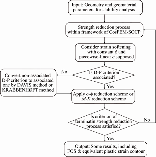
Figure 1 Flowchart of FORTRAN procedures for strength reduction process within framework of CosFEM-SOCP
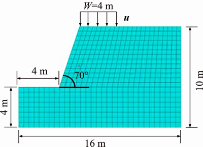
Figure 2 Slope example with restrained displacement on its top
The equivalent plastic strain contours at different restrained displacement steps are given in Figure 6. By using the CosFEM-SOCP (lc=0.5 m, nels=544) method, the sequence of equivalent plastic strain contours obtained at different restrained displacement steps may reveal the progressive failure process of a slope. The potentially progressive failure process of a slope may be divided into three stages, namely initial failure occurring at the slope toe, the next failure occurring at the loading edge of slope top and through-going of the plastic zone or the slip surface. Based on the staged process of progressive failure of a slope, it can be concluded that the preferred location of reinforcing shall be near the slope toe, and the occurrence of plastic zone at the loading edge of slope top may provide an alert of subsequently through-going slip surface.
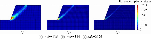
Figure 3 Equivalent plastic strain contours obtained by FEM-SOCP (u=0.05 m):
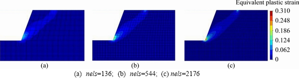
Figure 4 Equivalent plastic strain contours obtained by CosFEM-SOCP with lc=0.5 m (u=0.05 m):
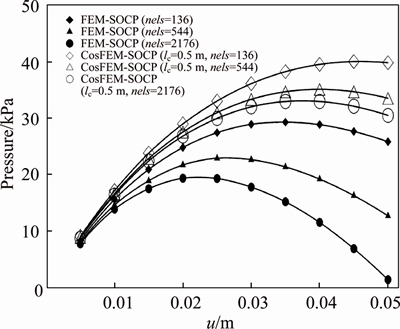
Figure 5 Pressure-displacement curves obtained by FEM-SOCP and CosFEM-SOCP
As we know, a residual factor of cohesion Rc can be defined as:
 (34)
(34)
Correspondingly, the contours of Rc for the slope at those steps of Figure 6 are given in Figure 7. It is clearly seen that the potentially progressive failure process of a slope is largely dependent on the softening process of cohesion. At the step of Nstep=2, there is no softening in initial cohesion implied by Rc=0. The softening process of cohesion occurs initially at the slope toe, as shown by Figures 7(b) and (c).
The rotational DOF (wz) obtained by CosFEM- SOCP for Nstep=10 is shown in Figure 8. Similar to the equivalent plastic strain contour, the relatively larger rotation mainly occurs at the slope toe or the slope top, while the rotational effect at the region far from the slip surface can be ignored, implying that the micro-polar continuum does not play a role in the far region. Again, the shear band width with rotations of soil particles is also closely related to lc.
To investigate the effects of lc on slope stability, the fine mesh (nels=2176) is adopted, and lc is taken as 0.6, 0.8 and 1.0 m, respectively. It is also seen from Figure 9 that a larger lc may generally result in a higher FOS. Compared to FEM-SOCP (i.e., CosFEM-SOCP with lc=0), CosFEM-SOCP with lc=0.6, 0.8 and 1.0 m may lead to the FOS averagely increase 8.9%, 11.4% and 15.3%, respectively. Hence, the internal characteristic length lc shall not be neglected for the slope with strain softening as well, because doing so may produce overly conservative estimations on geotechnical stability as well as uneconomical geotechnical design. Additionally, a general trend that FOS may decrease with the softening or the ��loading�� process can also be observed. For CosFEM-SOCP with lc=0.6, 0.8 and 1.0 m, the decreased percentage of FOS from the step of Nstep=0 to the step of Nstep=10 is about 16.5%, 19.0% and 21.1%, respectively, which is obviously higher than 8.8% of FEM-SOCP. As a result, it may be concluded that softening in soil strength may have more evident effects on the geotechnical failures with certain internal characteristic length. Moreover, neglecting the softening of soil may lead to unsafe estimations on geotechnical stability, which shall be obviated.
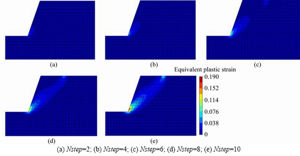
Figure 6 Sequence of equivalent plastic strain contours obtained by CosFEM-SOCP (lc=0.5 m, nels=544) at different restrained displacement steps:
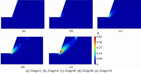
Figure 7 Sequence of Rc contours obtained by CosFEM-SOCP at different restrained displacement steps:
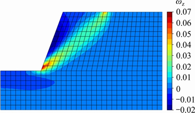
Figure 8 Rotational DOF (wz) obtained by CosFEM-SOCP for Nstep=10
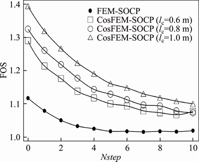
Figure 9 FOS obtained by FEM-SOCP and CosFEM-SOCP for the fine mesh (nels=2176)
3.2 Stability and localization analysis of a multilayered soil slope
To further assess the effects of lc, a three- layered non-homogeneous soil slope example previously investigated by CHEN et al [30] is revisited, as shown in Figure 10. In the present study, however, the internal characteristic length lc is considered, and the soils of the slope are assumed to obey the D-P failure criterion with strain softening. For the parameters of soils adopted in this slope example, refer to Table 2. It is worth mentioning that since the experimental data of defining lc are absent, the same lc is still assumed for all the three soil layers without loss of generality. The total vertical displacement of u=0.4 m is applied in 20 equal increments (i.e., Nstep=20, u=0.02 m). To assess the effects of the mesh density on numerical results, three mesh discretization (nels=1335, 2370 and 5543) are generated, respectively.
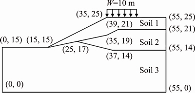
Figure 10 Geometry of multilayered soil slope
When the total vertical displacement of u= 0.4 m (i.e., Nstep=20) is reached, the equivalent plastic strain contours obtained by FEM-SOCP and CosFEM-SOCP are shown in Figures 11 and 12, respectively. It is still seen that when FEM-SOCP is applied, the shear band width decreases with mesh refining. When CosFEM-SOCP is applied, however, the shear band dominated by lc is almost kept unaffected as long as the adopted meshes are fine enough, and it is not easy to detect a legible slip surface like in the contours from FEM-SOCP. Figure 13 shows the pressure-displacement curves obtained by FEM-SOCP and CosFEM-SOCP. For the pressure-displacement responses calculated by FEM-SOCP with two mesh densities (i.e., nels=1335 and nels=5543), a distinct difference in the responses at the strain-softening stage can be observed. Nevertheless, the pressure-displacement responses calculated by CosFEM-SOCP (lc=1.0 m) are still in the pre-softening stage, different from those illustrated in Figure 5. For the last step (i.e., Nstep=20), the relative pressure error between the two meshes is 4.5% for CosFEM-SOCP, which is much smaller than 40.4% of FEM-SOCP. It is also interesting to note that due to the coupling effects of lc and strain softening, the softening behavior of geomaterial tends to be postponed. Particularly, the bearing capacity of a geotechnical system may be significantly underestimated, if the effects of lc are not modeled or considered in the numerical analyses.
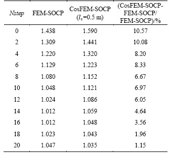
Furthermore, lc is set as 0.5, 1.0 and 1.5 m, respectively. The curves of FOS obtained by CosFEM-SOCP with the fine mesh (i.e., nels=5543) are given in Figure 14, and CosFEM-SOCP in conjunction with lc=0, which is actually set as a very small value in numerical implementations, may reduce to FEM-SOCP. It is particularly emphasized here that if the FEM-SOCP method is applied, the lowest value of FOS corresponding to the peak value of pressure loading may be found at the step of Nstep=15. In other words, the FOS calculated by FEM-SOCP or CosFEM-SOCP shall be positively correlated to the equivalent uniform reaction pressure, and the peak point at the pressure-displacement curve corresponds to the lowest FOS. Additionally, for the smallest lc (i.e., 0.5 m), the average of relative errors between FEM-SOCP and CosFEM-SOCP is about 6.0% as specified in Table 3, and the average of relative errors shall be more evident for a larger lc.
Table 2 Soil parameters of multilayered soil slope
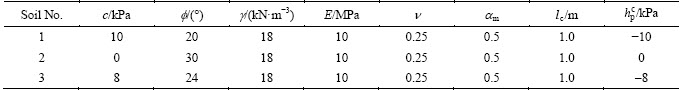
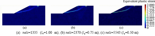
Figure 11 Equivalent plastic strain contours obtained by FEM-SOCP (u=0.4m):
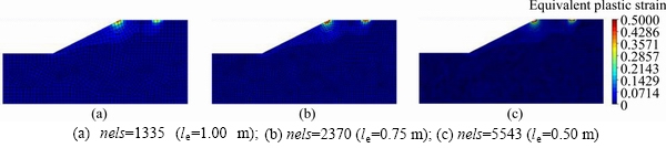
Figure 12 Equivalent plastic strain contours obtained by CosFEM-SOCP (u=0.4 m):
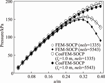
Figure 13 Pressure-displacement curves obtained by FEM-SOCP and CosFEM-SOCP for the multilayered soil slope
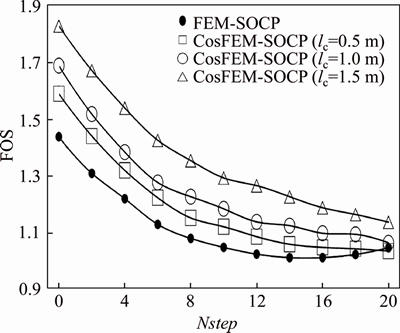
Figure 14 FOS obtained by FEM-SOCP and CosFEM- SOCP with different lc for fine mesh (nels=5543)
Table 3 FOS and relative error obtained by FEM-SOCP and CosFEM-SOCP with lc=0.5 m
4 Conclusions
Nowadays, most geotechnical stability analyses have been performed without considering the effects of shear band width. To improve the understanding on geotechnical stability, the actual shear band width shall be adequately reflected in numerical simulations. Hence, the effects of the micro-polar continuum in geotechnical failure analyses are investigated within the mathematical programming optimized finite element framework, and some observations or concluding remarks are summarized as below.
1) Based on the stability analyses of two slope examples (i.e., one homogeneous soil slope and one multilayered soil slope), it can be observed that lc plays a crucial role in the geotechnical stability analysis, and the calculated FOS values shall be positively correlated to lc predefined in the micro- polar continuum. Generally, the underestimations on the FOS of a geotechnical system may be as high as about 20%, depending on the prescribed lc. Hence, classical continuum may lead to remarkable underestimations on the geotechnical stability as well as uneconomical geotechnical design.
2) Based on the investigated geotechnical examples, it is observed that when the classical continuum is applied, the shear band width may decrease with mesh refining. When the micro-polar continuum is applied, however, the shear band width dominated by lc is almost kept unaffected as long as the adopted meshes are beyond a certain density, indicating that the mechanism of geotechnical failure attained from micro-polar continuum could be different from the (more localized) one attained from the classical continuum. Hence, the micro-polar continuum is capable of capturing the non-local geotechnical failure characteristic.
3) Since lc is one of the key parameters in the micro-polar continuum for modeling the non-local failure mechanism, it deserves more in-depth investigations from the micro-physical perspective. Without loss of generality, constant lc are still assumed for soil layers. It is found that due to the coupling effects of lc and strain softening, the softening behavior of geomaterial tends to be postponed. Additionally, the bearing capacity of a geotechnical system may be significantly underestimated, if the effects of lc are not modeled or considered in the numerical analyses.
Contributors
CHEN Xi provided the concept and edited the manuscript. WANG Dong-yong performed some analyses and wrote the first draft. TANG Jian-bin performed some analyses and provided some numerical results. MA Wen-chen gave some revision suggestions on the first draft. LIU Yong edited the final revised draft.
Conflict of interest
CHEN Xi, WANG Dong-yong, TANG Jian-bin, MA Wen-chen and LIU Yong declare that they have no conflict of interest.
References
[1] GRIFFITHS D V, LANE P A. Slope stability analysis by finite elements [J]. G��otechnique, 1999, 49(3): 387-403. DOI: 10.1680/geot.1999.49.3.387.
[2] ZHAO Lian-heng, LI Liang, YANG Feng, LUO Qiang, LIU Xiang. Upper bound analysis of slope stability with nonlinear failure criterion based on strength reduction technique [J]. Journal of Central South University of Technology, 2010, 17(4): 836-844. DOI: 10.1007/s11771- 010-564-7.
[3] KRABBENHOFT K, LYAMIN A V. Strength reduction finite-element limit analysis [J]. G��otechnique Letters, 2015, 5(4): 250-253. DOI: 10.1680/jgele.15.00110.
[4] DENG Dong-ping, LI Liang, ZHAO Lian-heng. Limit equilibrium analysis for stability of soil nailed slope and optimum design of soil nailing parameters [J]. Journal of Central South University, 2017, 24(11): 2496-2503. DOI: 10.1007/s11771-017-3662-y.
[5] LIU Yong, ZHANG Wen-gang, ZHANG Lei, ZHU Zhi-ren, HU Jun, WEI Hong. Probabilistic stability analyses of undrained slopes by 3D random fields and finite element methods [J]. Geoscience Frontiers, 2018, 9(6): 1657-1664. DOI: 10.1016/j.gsf.2017.09.003.
[6] ZHANG Rui, LONG Ming-xu, LAN Tian, ZHENG Jian-long, GEOFF C. Stability analysis method of geogrid reinforced expansive soil slopes and its engineering application [J]. Journal of Central South University, 2020, 27(7): 1965-1980. DOI: 10.1007/s11771-020-4423-x.
[7] CHEN X, WU Yong-kang, YU Yu-zhen, LIU Jian-kun, XU X F, REN Jun. A two-grid search scheme for large-scale 3-D finite element analyses of slope stability [J]. Computers and Geotechnics, 2014, 62: 203-215. DOI: 10.1016/j.compgeo. 2014.07.010.
[8] TSCHUCHNIGG F, SCHWEIGER H F, SLOAN S W. Slope stability analysis by means of finite element limit analysis and finite element strength reduction techniques. Part II: Back analyses of a case history [J]. Computers and Geotechnics, 2015, 70: 178-189. DOI: 10.1016/j.compgeo. 2015.06.018.
[9] WANG Dong-yong, CHEN Xi, YU Yu-zhen, JIE Yu-xin, LYU Yan-nan. Stability and deformation analysis for geotechnical problems with nonassociated plasticity based on second-order cone programming [J]. International Journal of Geomechanics, 2019, 19(2): 04018190. DOI: 10.1061/ (ASCE)GM.1943-5622.0001339.
[10] MUHLHAUS H B, VARDOULAKIS I. The thickness of shear bands in granular materials [J]. G��otechnique, 1987, 37(3): 271-283. DOI: 10.1680/geot.1987.37.3.271.
[11] TEJCHMAN J, WU W. Numerical study on patterning of shear bands in a Cosserat continuum [J]. Acta Mechanica, 1993, 99(1-4): 61-74. DOI: 10.1007/BF01177235.
[12] TEJCHMAN J, WU W. Numerical simulation of shear band formation with a hypoplastic constitutive model [J]. Computers and Geotechnics, 1996, 18(1): 71-84. DOI: 10.1016/0266-352X(96)00004-3.
[13] GRACIO J J. The double effect of grain size on the work hardening behaviour of polycrystalline copper [J]. Scripta Metallurgica et Materialia, 1994, 31(4): 487-489. DOI: 10.1016/0956-716X(94)90024-8.
[14] SHARBATI E, NAGHDABADI R. Computational aspects of the Cosserat finite element analysis of localization phenomena [J]. Computational Materials Science, 2006, 38(2): 303-315. DOI: 10.1016/j.commatsci.2006.03.003.
[15] VOYIADJIS G Z, ALSALEH M I, ALSHIBLI K A. Evolving internal length scales in plastic strain localization for granular materials [J]. International Journal of Plasticity, 2005, 21(10): 2000-2024. DOI: 10.1016/j.ijplas.2005.01. 008.
[16] TANG Hong-xiang, SUN Fa-bing, ZHANG Yi-peng, DONG Yan. Elastoplastic axisymmetric Cosserat continua and modelling of strain localization [J]. Computers and Geotechnics, 2018, 101: 159-167. DOI: 10.1016/j.compgeo. 2018.05.004.
[17] WANG Dong-yong, CHEN Xi, LV Yan-nan, TANG Chong. Geotechnical localization analysis based on Cosserat continuum theory and second-order cone programming optimized finite element method [J]. Computers and Geotechnics, 2019, 114: 103118. DOI: 10.1016/j.compgeo. 2019.103118.
[18] CHANG Jiang-fang, CHU Xi-hua, XU Yuan-jie. Finite-element analysis of failure in transversely isotropic geomaterials [J]. International Journal of Geomechanics, 2015, 15(6): 04014096. DOI: 10.1061/(ASCE)GM.1943- 5622.0000455.
[19] CHU J, LO S C R, LEE I K. Strain-softening behavior of granular soil in strain-path testing [J]. Journal of Geotechnical Engineering, 1992, 118(2): 191-208. DOI: 10.1061/(ASCE)0733-9410(1992)118:2(191).
[20] READ H E, HEGEMIER G A. Strain softening of rock, soil and concrete: A review article [J]. Mechanics of Materials, 1984, 3(4): 271-294. DOI: 10.1016/0167-6636(84)90028-0.
[21] CONTE E, SILVESTRI F, TRONCONE A. Stability analysis of slopes in soils with strain-softening behaviour [J]. Computers and Geotechnics, 2010, 37(5): 710-722. DOI: 10.1016/j.compgeo.2010.04.010.
[22] ZHANG Ke, CAO Ping, BAO Rui. Progressive failure analysis of slope with strain-softening behaviour based on strength reduction method [J]. Journal of Zhejiang University SCIENCE A, 2013, 14(2): 101-109. DOI: 10.1631/jzus. A1200121.
[23] RAFIEI RENANI H, MARTIN C D. Factor of safety of strain-softening slopes [J]. Journal of Rock Mechanics and Geotechnical Engineering, 2020, 12(3): 473-483. DOI: 10.1016/j.jrmge.2019.11.004.
[24] LI Xi-kui, TANG Hong-xiang. A consistent return mapping algorithm for pressure-dependent elastoplastic Cosserat continua and modelling of strain localisation [J]. Computers & Structures, 2005, 83(1): 1-10. DOI: 10.1016/j.compstruc. 2004.08.009.
[25] REISSNER E. On a variational theorem in elasticity [J]. Journal of Mathematics and Physics, 1950, 29(1-4): 90-95. DOI: 10.1002/sapm195029190.
[26] KRABBENHOFT K, KARIM M R, LYAMIN A V, SLOAN S W. Associated computational plasticity schemes for nonassociated frictional materials [J]. International Journal for Numerical Methods in Engineering, 2012, 90(9): 1089-1117. DOI: 10.1002/nme.3358.
[27] ZHANG X, SHENG Dai-chao, SLOAN S W, BLEYER J. Lagrangian modelling of large deformation induced by progressive failure of sensitive clays with elastoviscoplasticity [J]. International Journal for Numerical Methods in Engineering, 2017, 112(8): 963-989. DOI: 10.1002/nme.5539.
[28] MOSEK, A. The MOSEK C optimizer for API C8.0.0.94 [OB/OL]. [2018-12-25] http://docs.mosek.com/8.0/capi/ index.html.
[29] DAVIS, E H. Theories of plasticity and failure of soil masses [M]// Soil Mechanics: Selected Topics, 1968: 341-354.
[30] CHEN Xi, WANG Dong-yong, YU Yu-zhen, LV Yan-nan. A modified Davis approach for geotechnical stability analysis involving non-associated soil plasticity [J]. G��otechnique, 2020, 70(12): 1109-1119. DOI: 10.1680/jgeot.18.p.158.
(Edited by ZHENG Yu-tong)
���ĵ���
����������������Ԫ������Ӧ���������������ȶ��Է���
ժҪ�����ھ������������۵��������ȶ��Է������ܻ�������������İ�ȫ�ԡ�Ϊ�˸��õ������������ȶ��ԣ������������壬�Ա����ڲ���������(lc)�ܹ�ģ����д����ȡ�����������Ϊ�������ڶ����滮��������������Ԫ�����о��ڲ�����������ģ���������ϼ��д������е����á��������������lc�����ӣ����ɾ�������������FOS�ĵ��������ԡ���Ӧ����������ʱ��ֻҪ�����㹻ϸ�������д���lc�����������ֲ��䣬�����ֵĻ������뾭�������岻ͬ���������������ܹ����Ǿֲ������ƻ�����������lc��Ӧ��������������ã��������ϵ�������Ϊ�����ͺ��⣬�������ֵ�����в�ģ�����lc��Ӱ�죬������ϵ�ij��������ܻᱻ���ص���
�ؼ��ʣ������ȶ��ԣ�Ӧ��ֲ������Ǿֲ������ƻ����������壻�ڲ���������
Foundation item: Projects(2017YFC0804602, 2017YFC0404802) supported by the National Key R&D Program of China; Project(2019JBM092) supported by the Fundamental Research Funds for the Central Universities, China
Received date: 2020-07-22; Accepted date: 2020-11-10
Corresponding author: CHEN Xi, PhD, Professor; Tel: +86-10-51684096; E-mail: xichen.geo@gmail.com; ORCID: https://orcid.org/ 0000-0001-7104-1537
Abstract: Geotechnical stability analyses based on classical continuum may lead to remarkable underestimations on geotechnical safety. To attain better estimations on geotechnical stability, the micro-polar continuum is employed so that its internal characteristic length (lc) can be utilized to model the shear band width. Based on two soil slope examples, the role of internal characteristic length in modeling the shear band width of geomaterial is investigated by the second-order cone programming optimized micro-polar continuum finite element method. It is recognized that the underestimation on factor of safety (FOS) calculated from the classical continuum tends to be more pronounced with the increase of lc. When the micro-polar continuum is applied, the shear band dominated by lc is almost kept unaffected as long as the adopted meshes are fine enough, but it does not generally present a slip surface like in the cases from the classical continuum, indicating that the micro-polar continuum is capable of capturing the non-local geotechnical failure characteristic. Due to the coupling effects of lc and strain softening, softening behavior of geomaterial tends to be postponed. Additionally, the bearing capacity of a geotechnical system may be significantly underestimated, if the effects of lc are not modeled or considered in numerical analyses.
