
J. Cent. South Univ. Technol. (2007)03-0319-05
DOI: 10.1007/s11771-007-0063-7
![]()
Variation regularity of metal magnetic memory signals with
inspecting time-interval and location
YAN Chun-yan(�ϴ���)1, LI Wu-shen(������)1, DI Xin-jie(ۡ�½�)1,
XUE Zhen-kui(Ѧ���)2, BAI Shi-wu(������)2, LIU Fang-ming(������)2
(1. School of Materials Science and Engineering, Tianjin University, Tianjin 300072, China��
2. Petroleum-Gas Pipeline Research Institute of China, Langfang 065000, China)
Abstract:
Influences of inspecting time-interval and location on varying behavior of metal magnetic memory (MMM) signals of defects were studied. Different areas in two precracked weldments were inspected at different time-intervals by type TSC-1M-4 stress-concentration magnetic inspector to obtain MMM signals. Mechanisms of MMM signals varying behavior with inspecting time and space were analyzed and discussed respectively. It is found that MMM signals don��t change with inspecting time-interval, since stress field and magnetic leakage field maintain unchanged at any time after welding. On the other hand, MMM signals differ greatly for different inspecting locations, because stress field and magnetic leakage field are unevenly distributed in defective ferromagnetic materials.
Key words:
nondestructive testing; metal magnetic memory; inspecting interval; inspecting location��
1 Introduction
Stress concentration is one of the fatal factors causing fatigue fracture of ferromagnetic equipments and structures. Effective early diagnosis and detection of stress-concentrated zones before damage are demanded to prevent abrupt failures. Reputed as the only effective nondestructive testing (NDT) method for early defect diagnosis and detection so far, metal magnetic memory (MMM) was firstly put forward at 50th International Welding Conference in 1997. Unlike conventional NDT methods, MMM inspecting technique can be utilized to implement early detection of defective parts with high stress concentration in inspected ferromagnetic structures and components[1-5]. The fundamental principle of MMM testing is to detect the self-magnetic leakage field, which generates in stable gliding-dislocation zones with stress concentration in ferromagnetic materials. In stress-concentrated parts of ferromagnetic structures, tangential component of magnetic leakage shows the maximum value; while normal component of the magnetic leakage shows to be zero. This phenomenon is the basis of MMM inspecting method that only involves measuring normal component of magnetic leakage to locate the stress-concentrated areas in a tested object[3-9].
Once MMM inspecting technique was put forward, it has aroused more and more attention from NDT researchers both in domestic and abroad. So far, a lot of research has been conducted on applications of MMM phenomenon; while insufficient work has been implemented on its related theoretical research. Up to now, studies on MMM signal features and related laws are still in early-stage probes. Application of this method in industrial damage detection is greatly limited due to the lack of substantial knowledge of MMM phenomenon. Accordingly, in-depth analysis and study of MMM signals are demanded to make this new method widely applied in industrial engineering cases. To explore more essential information of MMM signals, an experiment was carried out to study how MMM signals vary with inspecting time-interval and inspecting location.
2 Experimental
The test material used in this study was high-strength X70 pipeline steel. The chemical composition and mechanical properties are given in Tables 1 and 2, respectively. The MMM inspection was carried out by type TSC-1M-4 MMM inspector. Two plates with the same geometry were precracked by linear cutting and shielded metal arc welding (SMAW). A schematic diagram of precracked plate is shown in
Fig.1. One premade crack was cut into the size of 10 mm��10 mm and buried in a depth(represented by ��h��) of 5 mm below the surface, while another crack was cut into the size of 10 mm��3 mm with a depth of 9 mm. Each plate was machined into a ��U��-grooved configuration for latter welding, and annealed to release the stress caused by machine processing.
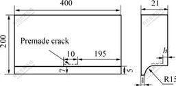
Fig.1 Schematic diagram of specimen with premade crack
Table 1 Chemical composition of X70 pipeline steel
(mass fraction, %)
Table 2 Mechanical properties of X70 pipeline steel
To simulate real welding cracks, we joined the two precracked plates with another two crack-free plates with the size of 400 mm��200 mm��21 mm. The butt- welding process was carried out by shielded metal arc welding(SMAW). The configuration of one butt-welded structure and the detecting process are shown in Fig.2. Hp-1, Hp-2 and Hp-3 represent normal component signals of three detecting sensors of MMM inspector, respectively. The postweld structures were marked with A and B respectively, then gridded to define different inspecting paths, as shown in Fig.3.

Fig.2 Schematic diagram of postweld structure and
inspecting process
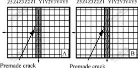
Fig. 3 Schematic diagram of postweld gridded structures
To obtain MMM signals, different areas in A and B were inspected at different inspecting intervals after welding. Inspecting schedule is given in Table 3. Distances between the welding seam and each detecting path are given in Table 4.
Table 3 Inspecting schedule
Note: Timing began when temperature of postweld structures dropped to 100 ��
Table 4 Distances between welding seam and
each inspecting path

3 Results and discussion
3.1 Regularity of MMM signals varying with inspecting time-interval
Hp-2 signals obtained along path Y1 in both A and B are shown in Fig.4. Signals numbered 1 to 3 were acquired over intervals of 3 h, 72 h and 8 d after butt-welding. It is noted that there is no change in inspection signals over eight consecutive days. Moreover, it is interesting to note that signals from the three inspecting sensors along all detecting paths show no change with inspecting time-interval. Thus we can presume that MMM signals don��t change with inspecting time-interval.
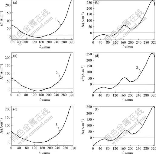
Fig. 4 MMM signals of path Y1 from 2nd detecting sensor
(a), (c), (e) Structure A��(b), (d), (f) Structure B
1��3 h after welding; 2��72 h after welding; 3��8 d after welding��
(LX��Displacement recorded by inspector��H��Normal component of magnetic leakage intensity)
Origin of the above-mentioned phenomenon is rooted in the microstructure of ferromagnetic structures[7-9]. After welding, specimen located in weak geomagnetic field will experience microstructure and phase transformation on cooling down to lower temperature. Since the premade cracks are located in welding heat-affected zone (HAZ), microstructures near crack tip will be under residual-stress effect during microstructure transformation. In geomagnetic field, when temperature falls below Curie point(about 764 ��), recrystallization occurs and a new magnetic constitution is developed[7]. On the other hand, diversified heterogeneity within the material results in a non-uniform distribution of microstructure. As is often the case, structural non-uniformity is located in defective zones with high stress concentration. Under magneto-mechanical effect, magnetic leakage field gradually develops along with the appearance of fixed nodes of magnetic domain near crack tip. In stress-concentrated areas, high stress energy is accumulated, while magnetic domain within the structure experiences a boundary shift or even an orientation rearrangement[7-15]. Consequently, magneto-elastic energy increases, and interior magnetic-field intensity rises to a level much higher than that of geomagnetic field. When temperature drops below 100 ��, stress field has already formed, and microstructure and stress field no longer change. Accordingly, magnetic field changes no more, and MMM signals do not change either. Thus it is asserted that MMM inspection is effective at any time during cooling process after welding.
It is not surprising to notice that trends of MMM signal variation in Figs.4(a) and (b) are clearly different. The reason is that the dimensions and locations of the premade cracks in A and B are different, so postweld stress field and magnetic field in the two structures differ accordingly. Consequently, MMM signals reflecting the magnetic-field intensity are different.
3.2 Regularity of MMM signals varying with inspecting location
Hp-2 curves were used again for the convenience of illustration. Fig.5 shows the inspecting signals of different inspecting paths in structure A, over a 24 h interval. Signals in Figs.5(a), (c) and (e) were obtained from path Y1, path Y3 and path Y5, respectively; while signals in Figs.5(b), (d) and (f) were obtained from path Z1, path Z3 and path Z5, respectively. As shown in Fig.5, signals vary greatly with distance between the weld and the detector. Besides, MMM signals for different inspected positions in structure B are also different. This phenomenon indicates that MMM inspecting signals are affected by spatial factors, and they are found to relate to the distance between the welding seam and the detector.
To interpret this phenomenon, it is recommended to analyze the inner stress field distribution first. Since welding is a local-heating process, stress field redistributes under welding thermal cycle effect in welding seam and HAZ. Consequently, magnetic leakage field changes in these areas, and a redistributed magnetic leakage field memorizing the stress state comes into being. Usually, longitudinal stress and transverse stress in welding seam and neighboring areas appear to be tensile with a level approaching yield strength of the material, whereas areas far from the welding seam are almost free from the heat cycle effect. Stress distribution in those distant areas differs from that in areas near the welding seam[16]. In the present study, microstructure and phase transformation are hardly observed in areas far away from the welding seam and the crack, and magnetic leakage intensity maintains at a low level due to the low-level residual stress. Therefore, a decline is observed in magnetic-leakage signal intensity as distance between the welding seam and the detector increases.
It is also noted that trends of signal variation on different sides of the welding seam in structure A are
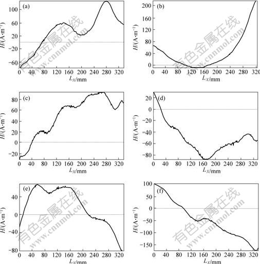
Fig.5 MMM signals of different paths in structure A from 2nd detecting sensor
(a) Y1; (b) Z1; (c) Y3; (d) Z3; (e) Y5; (f) Z5
(Lx��Displacement recorded by inspector; H��Normal component of magnetic leakage intensity)
different, as shown in Fig.5. Analysis of signals of structure B gives the same result. Explanation of this phenomenon is that welding residual stress in the component plates differs greatly at different sides of the welding seam. Since symmetric areas relative to the welding seam are not equidistant off the crack, stress fields on different sides are not symmetric due to the crack. Consequently, resultant magnetic leakage fields differ. Thus evident difference is observed in MMM signals obtained in different areas.
4 Conclusions
1) When ferromagnetic work pieces cool down after experiencing welding heat cycles, magnetic leakage field will come into being. MMM inspecting signals obtained at different inspecting intervals are consistent. Postweld MMM inspection result is found to be effective at any inspecting interval.
2) MMM inspection is quite sensitive to inspecting locations. Magnetic leakage field and stress field differ in different inspecting zones. MMM signal intensity varies when distance between the welding seam and the detector changes.
References
[1] DUBOV A A. A rapid method of inspecting welded joints utilizing the magnetic memory of metal[J]. Welding International(UK), 1997, 11(5): 410-413.
[2] DOUBOV A. Screening of weld quality using the magnetic metal memory effect[J]. Welding in the World(UK), 1998, 41(3): 196-199.
[3] DOUBOV A A. Express method of weldments inspection using metal magnetic memory[C]// Proceedings of 7th European Conference on Non-destructive Testing. Copenhagen, Denmark, 1998: 1266-1273.
[4] DOUBOV A A, DEMIN E A, MILYAEV A I, et al. The experience of gas pipeline stress-strain state control with usage of the metal magnetic memory method as compared with conventional methods and stress control means[J]. Welding in the World, 2002, 46(9/10): 29-33.
[5] DUBOV A. Principle features of metal magnetic memory method and inspection tools as compared to known magnetic NDT methods[J]. Canadian Institute for NDE Journal, 2006, 27(3): 16-20.
[6] CHEN Xing, LI Lu-ming, HU Bin, et al. Magnetic evaluation of fatigue damage in train axles without artificial excitation[J]. Insight, 2006, 48(6): 342-345.
[7] REN Ji-lin, LIN Jun-ming, CHI Yong-bing, et al. Metal Magnetic Memory Technique[M]. Beijing: China Electric Power Press, 2000. (in Chinese)
[8] LI Lu-ming, HUANG Song-ling, WANG Lai-fu, et a1. Research on magnetic testing method of stress distribution[J]. Trans Nonferrous Met Soc China, 2002, 12(3): 388-391.
[9] HUANG Song-ling, LI Lu-ming, SHI Ke-ren, et al. Magnetic field properties caused by stress concentration[J]. Journal of Central South University of Technology, 2004, 11(1): 23-26.
[10] HUANG S L, LI L M, Wang X F. Magnetic evaluation method for stress annealing of ferromagnetic materials[J]. Materials Technology (UK), 2005, 20(1): 5-6.
[11] LI Lu-ming, HUANG Song-ling��WANG Xiao-feng, et a1. A study of stress induced magnetic field abnormality[J]. Trans Nonferrous Met Soc China, 2003, 13(1): 6-9.
[12] LI Wu-shen, DI Xin-jie, BAI Shi-wu, et al. Feature analysis of metal magnetic memory signals for weld cracking-based on wavelet energy spectrum[J]. Insight, 2006, 48(7): 426-429.
[13] YAMASAKI T, YAMAMOTO S, HIRAO M. Effect of applied stresses on magnetostriction of low carbon steel[J]. Non-Destructive Testing and Evaluation International, 1996, 29(5): 263-268.
[14] BULTE D P, LANGMAN R A. Origins of the magneto-mechanical effect[J]. Journal of Magnetism and Magnetic Materials, 2002, 251: 229-243.
[15] DOUBOV A A. About physical base of method of metal magnetic memory[C]// 8th ECNDT Proceedings Abstracts Book. Barcelona, Spain, 2002. 132.
[16] TIAN Xi-tang. Welded Structure[M]. Beijing: China Machine Press, 1982. 47-52. (in Chinese)
(Edited by YANG Bing)
Foundation item: Project(50475113) supported by the National Natural Science Foundation of China; Project(20030056002) supported by Specialized Research Fund for Doctoral Program of Higher Education, China
Received date: 2006-06-24; Accepted date: 2006-09-27
Corresponding author: YAN Chun-yan, PhD: Tel: +86-22-27406261; E-mail: yanchunyan1982@126.com
