

Explicit FE wrinkling simulation and method to catch critical bifurcation point in tube bending process
YANG He(�� ��), LI Heng(�� ��), ZHAN Mei(ղ ÷), GU Rui-jie(�����)
Department of Materials Forming and Control Engineering,
Northwestern Polytechnical University, Xi��an 710072, China
Received 28 July 2006; accepted 15 September 2006
Abstract:
The wrinkling has become the main defect in the thin-walled tube NC bending process. In the study, a dynamic explicit FE model for aluminum alloy thin-walled tube NC bending process is developed to predict the wrinkling by using FE code ABAQUS/Explicit. Attention was paid to the influences of mass scaling, loading rate scaling, mesh density and element type on accurate wrinkling prediction. So the wrinkling modes and mechanism are revealed based on the reliable FE model. Then a two step strategy is proposed to capture the critical bifurcation point for the optimal design process. The results show: 1) The boundary conditions determine the tube materials response greatly so that the frequency analysis is meaningless to the simulation. It is the contact conditions that make the effect of the mass scaling and loading rate less significant.2) There are two wrinkling modes in the tube bending process. One refers to that local ripples occur initially in the straight regions contacted with wiper die and mandrel; the other refers to that local wrinkles occur in the curved regions due to the relative slipping between tube and clamp die. 3) Both the difference of the in-plane compressive stresses and the relative slipping distance are chosen to be the quantitative indexes to represent the critical point and wrinkling tendency. The experiment of aluminum alloy (5052 O) tube bending was carried out to verify whether the above wrinkle modes exist and the indexes proposed are reasonable to catch the critical bifurcation point. The results may help better understanding of the wrinkling mechanism and the process optimization of the tube bending.
Key words:
aluminum alloy; tube bending; wrinkling; critical bifurcation point; ABAQUS/Explicit;
1 Introduction
The thin-walled tube NC bending technology has been applied widely in aviation, aerospace, automobile, ship building and other high technical industries, etc, due to its satisfactory high strength/mass ratio, high efficiency, high precision and good flexibility [1]. But in the process, any deviation of the forming parameters influences the deformation state and thus provokes the wrinkles in the inner regions subjected to compressive stresses. Essentially, the process is a tri-nonlinear physical process with multi-factors interactive effects and dynamic conditions, as shown in Fig.1. Furthermore, the non-uniform deformation degree will be enhanced under increasing demands for thin-walled tubes with large diameter and small bending radius. The modeling of thin-walled tube NC bending process is a rather complex procedure, since it involves large plastic deformation and complicated boundaries, especially for the accurate wrinkling prediction.
Recently, the explicit FEM algorithm has become the main method to solve the complex process with unique advantages such as ability of predicting wrinkling directly without imperfections introduction. However, there��re problems in Explicit FE wrinkling prediction. 1) The prediction accuracy is much sensitive to the mass scaling, loading rate scaling, element type and mesh discretization. 2) The post-wrinkling can be well presented by the Explicit algorithm, but it is difficult to obtain the critical wrinkling conditions (bifurcation point) directly. Many scholars have investigated the wrinkling of the thin-walled parts forming processes [2-14]. But up to now, little is involved into the accuracy of the explicit FE wrinkling prediction for the complex forming process with dynamic contact boundary conditions, such as tube NC bending.
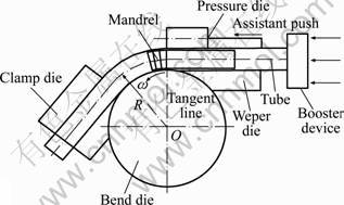
Fig.1 Diagram of NC tube bending process
In the study, an explicit FE model for aluminum alloy tube bending process has been established and the influences of mass scaling, loading rate scaling, mesh density and element type on wrinkling prediction are studied. Then the wrinkling mechanism is studied and various quantitative indexes are compared to ensure that the selected ones can represent the critical wrinkling point and wrinkling tendency. Finally, the experiment is used to confirm the results.
2 Methodology
2.1 Explicit FE modeling
A 3D Explicit FEM model (shown in Fig.2.) is established using ABAQUS/Explicit, including bending process, balls retracting and unloading process. The conclusions drawn from these results should be independent of the software package chosen [15].
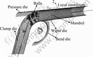
Fig.2 Explicit FE model for NC bending process
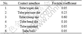
The elastic-plastic model with transverse anisotropy was used. The uniaxial tension test is employed to obtain the aluminum alloy (5052 O) properties (shown in Table 1). And the anisotropic plastic behavior was described with Hill��s yield function. The classical Coulomb model has been chosen to represent interfaces�� friction��conditions. Table 2 shows friction coefficients of different interfaces in stable bending process.
KAWKA et al[12] have found the number, distribution and shape of wrinkles are very sensitive to the initial blank mesh. But the element types, mass scaling factor and loading rate scaling factor may also influence the accuracy of the final wrinkling results.
Table 1 Mechanical properties of tube
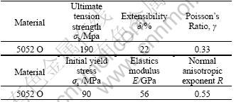
Table 2 Friction conditions in various contact interfaces
2.2 Experiment
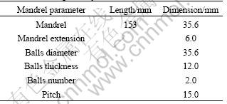
Tube outside diameter D is 38 mm, thickness t is 1mm, the bending radius R is 57 mm. The bending angle is 90?. The tooling parameters are shown in Table 3 and Table 4. Different friction levels are adopted to lubricate various contact interfaces. The mandrel extension e is adopted to control the wrinkling. Fig.3 shows that when e is less than 0 mm, the wrinkling is provoked.
Table 3 Tooling geometry dimension
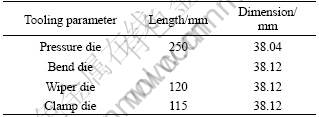
Table 4 Mandrel geometry dimension
3 Results and discussion
The ratio of the dynamic energy to the internal energy is used to be the general criterion before the more refined judgment. The criterion for the simulation accuracy is the configurations. The calculation conditions are corresponding to the experiment. e is set to -2 mm to provoke the obvious wrinkles.
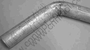
Fig.3 Wrinkled tube with e of -2 mm
3.1 Loading rate scaling and mass scaling
For the tube bending process, the typical bending speeds are on the order of 10 r/min (1 rad/s). For the bending operation in the study, the natural time for bending is 1.57 s without considering the ball retracting and unloading process).
By the frequency analysis, the lower mode frequency is 998.78 Hz, corresponding to 1 ms or periodical time. So the upper limit of the loading speed is 1 570 rad/s. It is found that even the inertia effects for 8 rad/s is too significant to accurately predict the wrinkling. It is concluded that for tube bending process, the increasing of the loading speed to reduce computation cost is not suggested, because the application of the complex couples contact conditions in simulation is closely related to the bending speed and the bigger loading speed makes the localized instability more prone to occur with obvious oscillation of kinematic energy. Fig.4 shows that the wrinkling occurs with loading rate scaling factor of 20, which disagrees with experiment definitely.
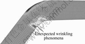
Fig.4 With loading rate scaling factor of 20
Thus, the nature bending speed 0.8 rad/s without loading rate are adopted in FE and various mass scaling factors are ranging from 500 to 15 000. Fig.5 shows that the changes of kinematic energy for different scaling factors are not big. Fig.6 shows that increasing the mass scaling factor can speed up the computation time efficiently and the even larger mass scaling factor still ensures the stable simulation. But it is found that the computation time is reduced sharply at first, and then it is reduced slowly when the mass scaling factor reaches the certain one. For the tube bending process, the certain value is 5 000 or so.
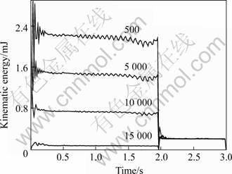
Fig.5 Kinematic energy
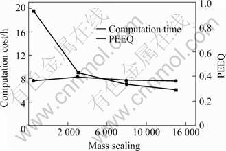
Fig.6 Computation time and PEEQ with different mass scaling factors
3.2 Element type and density
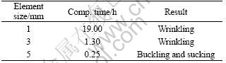
The mass scaling factor 10 000 is used. The element types are as follows. 1) S4R: 4-node doubly curved shell, reduced integration, enhanced hourglass control, finite membrane strains, considering the transverse shear strain. 2) S4RS: small membrane strains. 3) SC8R: 8-node quadrilateral in-plane general-purpose continuum shell, reduced integration with enhanced hourglass control, finite membrane strains, with 1 and 2 layers for meshing through the thickness. 4) C3D8R: 8-node linear brick, reduced integration, enhanced hourglass control, with 1, 2, 3, 4 layers through the tube thickness. The element sizes vary from 0.5 mm to 15 mm. The tube and dies are meshed evenly. And e is -2 mm, which provokes the wrinkling in the experiment.
Table 5 shows that either the solid element or continuum-shell element can not predict the wrinkling. And for shell element, both the finite strains and small strains have the same effect on the wrinkling prediction. Table 6 shows that the mesh size of 3 mm satisfies the accuracy and efficiency of simulation. So it is recommended that the shell element and 3 mm element size are adequate for simulation accuracy.
Table 5 Simulation results with different element types
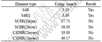
Table 6 Simulation results with different element sizes
3.3 Wrinkling behaviors and critical bifurcation point
Various groups of boundary conditions and tooling parameters are changed. It is found, from mechanical view of point, there are two compressive instability modes. One refers to that the local ripples occur initially in the straight regions contacted with both wiper die and mandrel. If the wrinkling is severe enough, then the wrinkles spread into the curved regions contacted with bend die and not ��iron�� definitely by the bend die. Otherwise, they only remain in the straight zones. The other mode refers to that the local wrinkles occur in the curved regions due to the relative slipping L between tube and clamp die, which causes the tube materials pile up and thus block the flow of the past materials. So the nonuniform compressive stress takes place in the curved regions and provokes the wrinkles. Fig.7(a) shows the first wrinkling mode and Fig.7(b) should the second phenomenon. The above wrinkling modes are all observed in the previous experiment.
But the critical bifurcation point and the development can not be observed directly in the experiment. Only the final configuration is obtained. Some scholars have adopted several methods to capture the instability in the sheet forming process, such as energy based wrinkling indicator and bifurcation indicator. In the study, several optional criterions are selected as quantitative indexes to capture the critical bifurcation point and represent the wrinkling tendency, such as the tangent compressive stress at the intrados, in-plane compressive stress ratio at the intrados. The materials and boundary conditions need not be considered in the indexes, which simplifies the wrinkling prediction process.
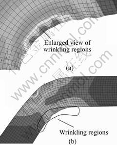
Fig.7 Wrinkling modes in bending process: (a) With mandrel extension of -2 mm; (b) With excessive friction between tube/mandrel
Two groups tests are used to obtain the index. 1) The clearance of tube/mandrel (balls) ranges in the span {0.9, 0.5, 0.2}; 2) The FOC between tube/mandrel (balls) ranges in the span {0.1, 0.2, 0.3}. According to the deformed meshes, it is observed that the wrinkling occurs when the clearance between tube/mandrel is 0.5 or 0.9, or when the friction coefficient is 0.2 or 0.3.
Fig.8(a) shows that even though severe wrinkling occurs with clearance 0.9 mm and 0.5 mm, the corresponding maximum tangent compressive stress is less than the one with the clearance 0.2 mm. The wrinkling in NC bending process is conditional on the double in-plane compressive stress state. Furthermore, the difference between in-plane maximum compressive stresses at the intrados is proposed as f=��tangent- ��circumferential. Fig.9 shows that the index is reasonable for the first group because the wrinkling occurs near the tangent line. But for the second group, the index is not feasible due to the different mechanism, namely the wrinkling is induced by slipping L between tube/clamp die. The L is much larger than others when the friction coefficient is 0.2 and 0.3. So a two-step strategy is proposed to predict wrinkling.1) Firstly, the difference of in-plane compressive stress J at the intrados is adopted to catch the wrinkling point near the tangent point. 2) Next, the relative slipping distance L is monitored to judge whether the wrinkles occur in the curved regions. The experiment is carried out to verify whether the method proposed is feasible to catch the critical bifurcation point.
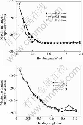
Fig.8 History curves of maximum tangent stress at intrados under different conditions: (a) Different clearance between tube/mandrel; (b) Different friction conditions between tube/mandrel
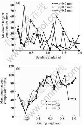
Fig.9 Difference between in-plane maximum compressive stresses at intrados: (a) Different clearance between tube/mandrel; b) Different friction conditions between tube/mandrel
4 Conclusion
It is found that the contact conditions make the effect of the mass scaling and loading rate to be less significant. Whether the wrinkling occurs and their positions are accurately predicted enough. The all-possible wrinkling modes and their mechanism have been revealed by changing the boundary conditions and tooling parameters. A two-step strategy is proposed to capture the bifurcation point. The strategy can be used to the optimizing of the forming parameters.
References
[1] YANG He, SUN Zhi-chao, LIN Yan, LI Ming-qi. Advanced plastic processing technology and research progress on tube forming [J]. Journal of Plasticity Engineering, 2000, 8(2): 86-88.(in Chinese)
[2] YANG He, ZHAN Mei, LIU Yu-li. Some advanced plastic processing technologies and their numerical simulation [J]. Journal of Materials Processing Technology, 2004, 151: 63-69.
[3] KIM J, KANG Y H, CHOI H H, HWANG S M, KANG B S. Comparison of implicit and explicit finite-element methods for the hydroforming process of an automobile lower arm[J]. Int J Adv Manuf Technol, 2002, 20: 407-413.
[4] KIM J, KANG Sung-jong, KANG Beom-soo. A comparative study of implicit and explicit FEM for the wrinkling prediction in the hydroforming process [J]. Int J Adv Manuf Technol, 2003, 22: 547-552.
[5] BILBAO A, ZARRAOA A, BIAKARGUENAGA A, ARINO J, JONKER F, KWAKKEL H. Using ABAQUS/Explicit in the development of a new can concept[A]. Proceedings of ABAQUS Users�� Conference[C]. Maastricht, the Netherlands, 2001.
[6] LI Heng, YANG He, ZHAN Mei. Wrinkling limit based on FEM virtual experiment during NC bending process of thin-walled tube [J]. Material Science Forum, 2004, 471-472: 498-502.
[7] LI Heng, YANG He, ZHAN Mei. Numerical research on wrinkling onset during the NC bending process of thin-walled tube [A]. Proceedings of the 6th International Conference on Frontiers of Design and Manufacturing [C]. Xi��an, 2004: 435-436.
[8] YANG He, LIN Yan. Wrinkling analysis for forming limit of tube bending process [J]. Journal of Materials Processing Technology, 2004, 152: 363-369.
[9] LI Heng, YANG He, ZHAN Mei, GU Rui-jie. A new method to accurately obtain wrinkling limit diagram in NC bending process of thin-walled tube with large diameter under different loading paths[J]. Journal of Materials Processing Technology, 2006, 177: 192-196.
[10] LI Heng, YANG He, ZHAN Mei, GU Rui-jie. Forming characteristics of thin-walled tube bending process with small bending radius[J]. Trans Nonferrous Met Soc China, 2006, 16: 613-619.
[11] ABEDRABBO N E. Experimental and Numerical Investigation of Stamp Hydroforming and Ironing of Wrinkling in Sheet Metal Forming[D]. Michigan State University, 2002.
[12] KAWKA M, OLEJNIK L, ROSOCHOWSKI A, SUNAGA H, MAKINOUCHI A. Simulation of wrinkling in sheet metal forming[J]. J Mater Proc Tehnol, 2001, 109: 283-289.
[13] HALVORSEN F, AUKRUST T. Studies of the mechanisms for buckling and waving in aluminum extrusion by use of a Lagrangian FEM software [J]. International Journal of Plasticity, 2005. (in Press)
[14] LI Heng, YANG He, ZHAN Mei, SUN Zhi-chao, GU Rui-jie. Role of mandrel in NC precision bending process of thin-walled tube [J]. International Journal of Machine Tools & Manufacture, 2006, accepted.
[15] Hibbit Karlson and Sorensen Inc, ABAQUS Version 6.4, 2005.
(CHEN Ai-hua)
Foundation item: Projects (59975076 and 50175092) supported by the National Natural Science Foundation of China; Project (50225518) by the National Science Found of China for Distinguished Young Scholars; Project by the Teaching and Research Award Program for Outstanding Young Teachers in Higher Education Institutions of MOE, PRC; Project (20020699002) by the Specialized Research Fund for the Doctoral Program of Higher Education of MOE, PRC; Project (04H53057) by Aviation Science Foundation
Corresponding author: YANG He; Tel: +86-29-88495632; Fax: +86-29-88495632; E-mail: yanghe@nwpu.edu.cn
