

Structural optimization for ball valve made of CF8M stainless steel
Xue-Guan SONG, Seung-Gyu KIM, Seok-Heum BAEK, Young-Chul PARK
Department of Mechanical Engineering, Dong-A University, Busan 604-714, Korea
Received 2 March 2009; accepted 30 May 2009
Abstract:
The mechanical and chemical properties of CF8M were studied through experiments. An application of CF8M in valve body was analyzed by using finite element method(FEM) to evaluate the structural safety. An optimization containing several variables based on the response surface method(RSM) was conducted to find the optimum dimension of the valve. The results show that using this process can save valve mass as well as the computational expense effectively.
Key words:
ball valve; CF8M stainless steel; trade-off method; response surface method; optimization;
1 Introduction
Ball valve has been used widely in various industries. It is opened by turning a handle attached to a ball inside the valve. The ball has a hole or port through the middle, so that when the port is in line with both ends of the valve, the flow will occur. When the valve is closed, the hole is perpendicular to the ends of the valve, and the flow is blocked. The ball valves are durable and usually work to achieve perfect shut-off even after years of disuse.
In the past, it was difficult to investigate details of the flow inside a ball valve, because it was not transparent. This difficulty also blocked the comprehension and improvement of ball valves. Along with the development of computer technique, the visualizations of flow pattern and fluid-structure interaction analysis become easier and easier.
Many researches have studied the flow inside a ball valve. KERH et al[1] utilized the finite element method to simulate transient interaction of fluid and structure in a control valve. MERATI et al[2] adopted a commercial package, FLUENTTM, to investigate the flow around a V-sector ball valve. DAVIS and STEWART[3] adopted FLUENTTM to study the flows in global control valves. CHERN et al[4] investigated the performance test and flow visualization of ball valve using a particle tracking flow visualization method. In recent researches both fluid characteristics and structure safety are considered simultaneously. SONG et al[5] performed a structural design of a butterfly valve by using topology optimization and size optimization.
The main purpose of this study is to optimize the fluid coefficient, the mass and structure safety of a ball valve at the same time. First, the material experiment was carried out to research the properties of ASTM A296 CF8M, of which the ball inside valve was made. Then, CFD and FEM analyses of this type of ball valve were performed, respectively, to calculate the pressure loss coefficient and the maximum stress on the valve disc. At last, the computer experiments and optimization method were conducted to obtain the optimum result.
2 Geometry and material properties
The ball valve studied in this work has a segmental structure, as shown in Fig.1. With trunnion mounting, the ball is supported by the upper stem and lower stem at the opposite position. The ball is made of CF8M, which is a modification of the CF8 type of which molybdenum is added to enhance the general corrosion resistance and to provide greater strength at elevated temperature.
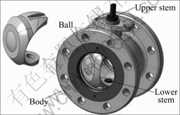
Fig.1 Segmental ball valve
Fig.2 shows the microstructure of CF8M austenitic stainless steel. The microstructure is predominantly austenitic, with 5%-8% ferrite typically. The ferrite increases the strength during and immediately after solidification, which greatly reduces the possibility of hot-tear defects occurring. Under the heat treatment condition, the alloy has a predominantly austenitic structure with small amounts of ferrite (15%-25%) distributed throughout the matrix in the form of disconti- nuous pools. When the alloy is heated in the range of 427-871 �� (such as in a welding operation), the pools provide a preferred location for carbides to precipitate, thus tending to reduce susceptibility of the alloy to intergranular corrosion caused by precipitation of carbides at austenite grain boundaries. The amount of ferrite present decreases as carbon content of the alloy is increased. By suitable balancing of the compositions, the alloy can be wholly austenitic and non-magnetic. At operating temperature of 649 �� or higher, ferrite may transform to the brittle sigma phase. The maximum corrosion resistance, however, is associated with low carbon and high chromium contents, and for this reason, the partially ferritic CF8M type is usually employed at operating temperatures below 538 ��.
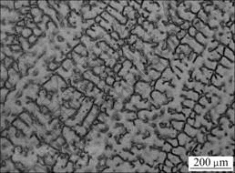
Fig.2 Microstructure of ASTM A296 CF8M stainless steel
Material properties of CF8M were obtained from experimental test of samples. The stress��strain curve is shown in Fig.3. And the corresponding material property of CF8M can be obtained as follows. The yield strength ��y, elastic modulus and Poisson��s ratio of CF8M are 308 MPa, 193 GPa and 0.27, respectively.
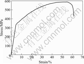
Fig.3 Stress��strain curve of CF8M stainless steel
3 Optimization of ball
3.1 Assumptions, loading conditions, and numerical analysis
Each ball valve manufacturer has its own loading conditions and corresponding criteria. The loading conditions are considered for the most serious service loads in practice. The loadings are composed of two conditions. One is related to the static pressure when the valve is closed, and the other is defined under flowing conditions with an approximate velocity of 3 m/s. The optimum closed and open conditions, which may be the worst loading condition among the service loadings, are taken into account during optimization process.
The FE model meshed with tetrahedral elements with first loading condition and CFD model with additional upward pipe and downward pipe are shown in Fig.4. After seven analyses (the valve is opened at 0?, 15?, 20?, 30?, 50?, 70?, 90?), as shown in Fig.5, it is found that the maximum stress of 158.1 MPa in the ball occurs at the connection place between ball and upper stem when the valve is closed.
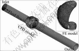
Fig.4 CFD and FE models
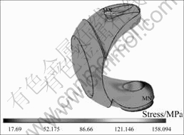
Fig.5 Distribution of von-Mises stress on ball
Fig.6 shows the pressure distribution at 50? opening degree, which is often used for this type ball valve. It can be seen from Fig.6 that the pressure decreases very obviously in the direction of fluid flowing. According to the analysis result, the safety factor is about 1.9, which is higher than the required value of 1.5. This implies that this initial design satisfies the strength requirement, and a new design can be conducted to reduce the mass of ball.
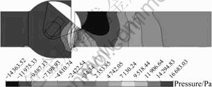
Fig.6 Pressure contour on middle plane at 50? opening degree
3.2 Problem formulation and scope
In terms of the previous analysis and the requirement of the user of this type ball valve, the design objectives are to minimize the mass of ball, the pressure loss coefficient K1 at 50? opening degree and maximum stress when the valve is closed, simultaneously. Hence, the objective and constraint functions could be defined as follows.
Minimize
Mass of ball, m; pressure loss coefficient, K1; maximum stress, ��max
Subject to
��max��205 MPa;
K1��1.0;
xlower��xi��xupper ![]() (1)
(1)
Having defined the objective and constraint functions, the next step is to identify the design variables. Although each dimension of the ball has more or less influence on the fluid performance, structural property and ball mass, for a given diameter of pipe, some dimensions such as the ball diameter and mounting stem hole cannot be modified, while only some aspects like fillet radius or thickness could be changed.
Fig.7 shows the six design variables of the ball to be optimized. They are the thickness of sealing wall, T; circle cape radius, R2; radiuses, R1, R3 and R4; and the sector angle, ��.
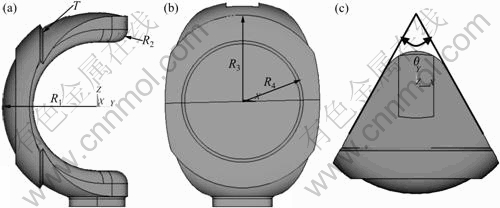
Fig.7 Design variables of ball: (a) Side view; (b) Front view; (c) Top view
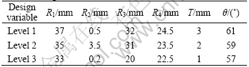
For this computer experiments, each design variable has three levels. Level 2 in Table 1 describes the initial dimension and the other two levels represent presumed values that are expected to achieve an improvement and not to distort the meshed FE and CFD elements. In the subsequent optimization process, the L18(21��37) orthogonal array is adopted, because it is a systematic and statistical way of computer experiment, which is widely used in designing experiments[6]. Then, the surrogate models are constructed by using the response surface methodology, and the trade-off method is utilized as the final optimization algorithm, because they are very cheap and suitable for the multi-objectives engineering optimization.
Table 1 Design variables and their levels
4 Implementation results
As explained above, response surface method is used to construct surrogate model. Having got the surrogate models of maximum von-Mises stress, pressure loss coefficient and ball mass, the trade-off method is utilized to get a trade-off optimum results among these three objectives. In this research, three optimization steps are developed to find the optimum result. The normalized normalized objective functions determined in these three optimization steps are shown in Fig.8, where Y* is the optimum value at each step and Y�� is the required objective value. To satisfy the constraint, each normalized objective function must exceed 1.0.
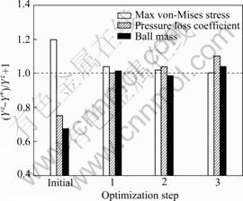
Fig.8 Normalized objective function of different optimization steps
Hence, the final optimum result is the result at the first step, and the corresponding variables to the optimum result are: R1=34.4 mm, R2=4.15 mm, R3=31.03 mm, R4=24.08 mm, T=1.95 mm and ��=57.5?.
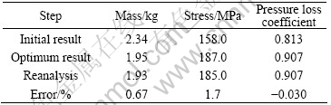
After the optimum design variables are determined, the conform experiment, also called reanalysis, is conducted to verify the accuracy of predicted values. The predicted optimum result and reanalysis result are compared in Table 2. The predicted ball mass and pressure loss coefficient are very close to their true values since their functions are not highly nonlinear, and the predicted maximum stress has a larger error, which implies that the design variables have more effect on the maximum stress. Also, the maximum error of 1.7% implies that the whole optimization process and the optimization result of ball are available and reliable.
Table 2 Comparison between optimum result and reanalysis result
5 Conclusions
1) The ASTM A296 CF8M is very suitable to ball valve, because the chromium and molybdenum are added to enhance general corrosion resistance and to provide greater strength at room and elevated temperature.
2) By performing the optimization using orthogonal array, response surface method and trade-off method, the mass of ball valve is reduced from 2.34 to 1.95 kg (16.67% from the initial design), while the maximum stress and pressure loss coefficient are still kept in the available range.
3) The optimum design presented work does not consider temperature effect. Since this type ball valve may work at high temperature, it is necessary to include the thermal analysis in optimization in the future work.
Acknowledgement
This work was supported by Technical Center for High-Performance Valves from the Regional Innovation Center(RIC) Program of the Ministry of Knowledge Economy (MKE), Korea
References
[1] KERH T, LEE J J, WELLFORD L C. Transient fluid-structure interaction in a control valve [J]. Journal of Fluids Engineering, 1997, 119(2): 354-359.
[2] MERATI P, MACELT M J, ERICKSON R B. Flow investigation around a V-sector ball valve [J]. Journal of Fluids Engineering, 2001, 123: 662-671.
[3] DAVIS J A, STEWART M. Predicting globe control valve performance��part II: Experimental validation [J]. Journal of Fluids Engineering, 2002, 124: 778-783.
[4] CHERN M J, WANG C C, MAC H. Performance test and flow visualization of ball valve [J]. Experimental Thermal and Fluid Science, 2007, 31(6): 505-512.
[5] SONG X G, WANG L, PARK Y C. Analysis and optimization of butterfly valve disc [J]. Proceedings of the Institution of Mechanical Engineers, Part E: Journal of Process Mechanical Engineering, 2009, DOI: 10.1243/09544089JPME236.
[6] HEDAYAT A S, SLOANE N J A, STUFKEN J. Orthogonal arrays: Theory and applications [EB/OL]. New York: Springer-Verlag, 1999, http://www.research.att.com/~njas/doc/OA.html.
Corresponding author: Young-Chul PARK; Tel: +82-51-200-6991; E-mail: parkyc67@dau.ac.kr
(Edited by LI Xiang-qun)
http://www.research.att.com/~njas/doc/OA.html." target="blank">[6] HEDAYAT A S, SLOANE N J A, STUFKEN J. Orthogonal arrays: Theory and applications [EB/OL]. New York: Springer-Verlag, 1999, http://www.research.att.com/~njas/doc/OA.html.
