

Phosphating process of AZ31 magnesium alloy and corrosion resistance of coatings
CHENG Ying-liang(��Ӣ��), WU Hai-lan(�⺣��), CHEN Zhen-hua(����),
WANG Hui-min(������), LI Ling-ling(������)
College of Materials Science and Engineering, Hunan University, Changsha 410082, China
Received 11 January 2006; accepted 27 April 2006
Abstract:
Zinc phosphate films were formed on AZ31 magnesium alloy by immersing into a phosphatation bath to enhance the corrosion resistance of AZ31. Different films were prepared by changing the processing parameters such as immersing time and temperature. The corrosion protection of the coatings was studied by electrochemical measurements such as electrochemical impedance spectroscopy, potentiodynamic polarization curves, and the structure of the films were studied by metalloscopy and X-ray diffraction (XRD). The results show that, the film formed at 80 ��, 10 min has the highest corrosion resistance. The XRD patterns show that the film consists of hopeite (Zn3(PO4)2��xH2O).
Key words:
AZ31 magnesium alloy; phosphating; corrosion; electrochemical impedance spectroscopy; potentiodynamic polarization;
1 Introduction
Magnesium alloys are relatively light structural materials, with excellent physical and mechanical properties��such as low density and high specific strength, excellent castability and good machinability. These properties make them ideal candidates for lightmass engineering applications, especially in the automotive industry, computer parts, aerospace industry and cellular phones where mass reduction is concerned[1-4]. However, magnesium and its alloys are characterized by low corrosion resistance, which limits their use. Their very low electrode potential easily leads to even reactivation in the atmosphere. Unfortunately, the natural oxide layer on magnesium surfaces is very loose and cannot offer an effective resistance to corrosion[5]. Therefore, it is very important to improve the anti-corrosion performances of magnesium alloys in industrial applications. Many protective surface treatments of magnesium alloys, including chemical conversion coating, anodizing, plating, metal coating and paint coating[6,7], have been widely studied for improving the corrosion resistance of Mg alloys. Now the chemical conversion coating with chromate containing solution is widely used in many applications for its low cost[8], but the chromate ion could cause serious environmental problems. To avoid the chromate process, many new substitutes have been studied, including the rare earth conversion coatings, stannate bath, permanganate bath, zinc phosphate conversion coating, etc[9-15].
In this work, a phosphate solution, which is free of chromate, is used to form the conversion coatings on the AZ31 alloy surface. The effect of processing time and temperature on the properties of the films is discussed. The structure and properties of the phosphated film are studied by metallographic microscopy, XRD, electrochemical impedance spectroscopy(EIS) and potentiodynamic polarization curves.
2 Experimental
Magnesium alloy AZ31 with a nominal composition of 3%Al, 1%Zn and 0.2%Mn (mass fraction) was chosen in this study. Samples were cut from an extruded AZ31 sheet and enveloped by epoxy with only one surface exposed as the working surface. The exposure area is 0.45 cm2. The samples were polished successively with 600 and 1 200 grit abrasive papers, then they were clean- ed in acetone and dried in a stream of warm air.
The composition of the bath is summarized in Table 1. It was chosen according to Ref.[14]. The bath contained phosphoric acid, phosphate ions, nitrates and nitrites, which were necessary for the magnesium oxidation. The bath also contained zinc and fluoride ions. Zinc ions in the form of zinc nitrate were added and zinc phosphate (ZnHPO4) was stabilized by phosphoric acid. Zinc ions were added to favor the formation of a crystalline film of tertiary zinc phosphate on the treated metal. Fluoride ions were added as an activation agent and the pH value of solution was approximately 3 and this condition supports the magnesium corrosion [14].
Table 1 Composition of phosphatation solution and processing parameters
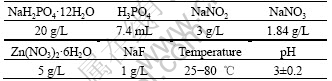
Phosphatation was carried out in a thermostated container. Before immersing into the phosphating bath, the sample was pretreated in 60%NaOH and 75%H3PO4 solution. The NaOH bath was used to clean the grease which covered on the sampler��s surface. And H3PO4 bath was used to dissolve the natural oxide layer on magnesium surface.
The effect of processing time and temperature was studied. Films were acquired by processing with different parameters, and the properties of the films were checked by electrochemical tests. Electrochemical tests were carried out in 3.5% NaCl solution (mass fraction) using a computer-monitored CHI660B (CH Instruments, Inc 3700 Tennison Hill Drive Austin, TX 78738-5012 USA). The test instrument was composed of a three-electrode system. A saturated calomel electrode (SCE) was used as a reference electrode. A large platinum sheet was used as an auxiliary electrode. The sample was the working electrode. Electrochemical impedance spectroscopy (EIS) tests and potentiodynamic polarization curves were taken to evaluate the properties of the samples. The EIS measurements were carried out at open circuit potential (OCP). The amplitude of the perturbative signal was 5 mV and the frequency range is between 0.01 Hz and 100 kHz. After the EIS measurements, the potentiodynamic electrochemical tests were carried out with a scan rate of 0.001 V/s. All of the tests were carried out at room temperature (about 25 ��).
The microstructure and the composition of the films were studied with a MM-6 metallography microscope (Leits, Germany) and X-ray diffractometer with CuK�� radiation(SIMENS D5000).
3 Results and discussion
3.1 Feature of open circuit potential during pho- sphating
In Fig.1, the OCP is shown as a function of time for the AZ31 alloy immersed in the phosphating bath. At first the OCP declines, and this process lasts about 200 s; after that, the OCP increases; at last it becomes stabilized. The drift of OCP to negative position is probably caused by the corrosion of AZ31 by the free phosphoric acid in the solution. At the same time, the phosphate films are formed on the metal surface, which will enhance the free corrosion potential of the sample, and this is shown on the later stage of OCP��time curves. After long time of phospahting, the surface of the sample is totally covered by phosphate films, and the OCP will be stable. It can be seen on Fig.1 that the OCP keeps constant after 3 000 s, which probably shows that the phosphating process is nearly finished after 3 000 s.

Fig.1 Open circuit potential of AZ31 magnesium sample as function of immersion time in phosphating bath at 80 ��
3.2 Effect of phosphating time
In this study, samples with different phosphating times were prepared and the corrosion resistance of the samples was studied by EIS and potentiodynamic polarization curves in 3.5% NaCl solution to evaluate the effect of phosphating time on the properties of the films. The EIS and potentiodynamic polarization results of the samples with different processing times at 50 �� are shown in Fig.2 and Fig.3, respectively.
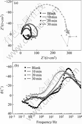
Fig.2 EIS of phosphate films with different immersion times at 50 ��: (a) Nyquist plots; (b) Bode-phase plots
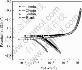
Fig.3 Potentiodynamic polarization results of samples with different phosphating times at 50 ��
The EIS results show that these diagrams are composed of two parts: one capacitive loops (in the high frequency range) and one inductive loop (in the low frequency range). The high frequency capacitive loop can be referred to the phosphate film. And this capacitive loop can be described by the equivalent electric circuit shown in Fig.4, in which Rs represents the solution resistance, Rct represents the charge transfer resistance of the phosphate coating. CPE is replaced by the so called constant phase angle element (CPE), ZCPE =1/Y0(jw)-n��0
Table 2 Fitted results of high frequency part of EIS results in Fig.2
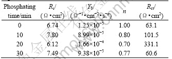
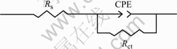
Fig. 4 Equivalent circuit used to fit high frequency part of EIS measurement
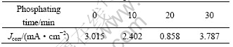
After the EIS measurement, the potentiodyamic polarization test is carried out, and the results are shown in Fig.3 and the free corrosion current density is calculated. The results are listed in Table 3.
Table 3 Fitted results of Jcorr in Fig.3
Both the charge transfer resistance (Rct) and the corrosion current density (Jcorr) can be used to evaluate the corrosion resistance of zinc phosphate film. Rct is in direct proportion to the corrosion resistance; while Jcorr is in inverse proportion to the corrosion resistance. If constructing 1/Rct and Jcorr in the same diagram, they will have the same tendency. Fig.5 shows the plot of 1/Rct and Jcorr to the phosphating time in this experiment.
Fig.5 shows that the tendency of 1/Rct is declined with the phosphating time at first, and reaches the minimum after 20 min immersion, then it increases again. The tendency of Jcorr with phosphating time is almost the same with that of 1/Rct. This means that at 50 ��, the best phosphating time is 20 min.

Fig.5 Relationship of 1/Rct and Jcorr with phospating time (phosphating temperature 50 ��)
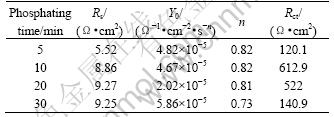
For the samples phosphated at 80 ��, EIS and potentiodynamic polarization tests were also performed and the results are shown in Figs.6 and 7. it is shown that the characteristic of the EIS and potentiodynamic polarization curves are similar to those at 50 ��. The diagrams of the EIS at 80 �� are also composed of two parts: one capacitive loops (at the high frequency range) and one inductive loop (in the low frequency range). So the EIS data can also be fitted to the equivalent circuit of Fig.4. The fitted result of EIS are listed in Table 4 and Jcorr value calculated from the potentiodynamic test is listed in Table 5, and the relationship of 1/Rct and Jcorr with the phospatation time is plotted in Fig.8.
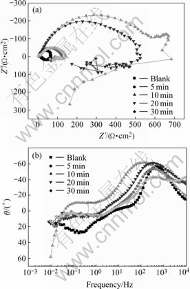
Fig.6 EIS of phosphate films with different immersion times at 80 ��: (a) Nyquist plots; (b) Bode-phase plots
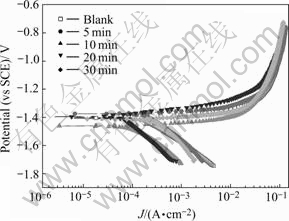
Fig.7 Potentiodynamic polarization results of samples with different phosphating times at 80 ��
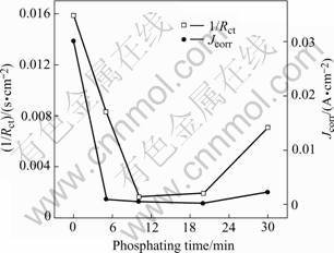
Fig. 8 Relationship of 1/Rct and Jcorr with phospating time (phosphating temprature 80 ��)
Table 4 Fitted results of high frequency part of EIS of samples phosphated at 80 ��
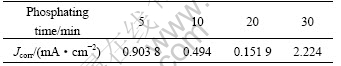
It is shown in Fig.8 that the values of 1/Rct and Jcorr first decrease with phosphating time and increase at the later stage of immersion. This is the same as the case at 50 ��. It should be pointed out that there is some dis- crepancy between the EIS results and the potentiodynamic results. In the EIS measurements, the largest value of Rct appears in the sample with processing time of 10 min, but the Jcorr acquired from potentiodynamic tests shows that the sample with 20 min processing possesses the least Jcorr value. This phenomenon should be ascribed to the different principles of the two techniques. The EIS measurement is a nearly non-perturbative technique, and it will not change the surface state of samples. But the potentiodynamic measurement needs large current density to polarize the sample to the Tafel region, which may change the surface state of the samples and bring some errors. This may be the reason for the discrepancy in the EIS and potentiodynamic result in this experiment and the criterion for the corrosion resistance of the samples should be taken according to the EIS measurements in large part. As a result, the best phosphating time is 10 min at 80 �� according to Fig.8.
Table 5 Jcorr for samples with different processing times at 80 ��
It can be seen in this experiment that there is an optimum processing time in phosphatation. If the immersion time is shorter than the best time, the film is not completely formed and it is very thin and loose, which will cause low anti-corrosion properties. If the immersion time is too long, the corrosion resistance is decreased, which may be caused by the dissolution of the film by the free-acid ion. The film become loose, the crystal will be much coarser and the anti-corrosion is lower. So it is importance to choose a proper time. At 50 ��, the proper time is 20 min and 10 min at 80 ��.
3.3 Effect of temperature
Temperature is another factor which affects the phosphatation. The Rct of the samples prepared at 50 �� and 80 �� are plotted with phosphating time in Fig.9. It shows that the Rct of the samples at 80 �� is higher than that of 50 ��. The higher the phosphating temperature, the higher the Rct is. This means the film��s corrosion resistance will be high when the phosphatation temperature increases.
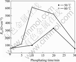
Fig.9 Relationship of Rct of samples treated at 50 �� and 80 �� with phosphating time
Phosphatation is a decalescence reaction. When the temperature is lower, the heat of the reaction is not enough to drive the reaction. At this situation, the rate of the phosphatation is slow, the formation time of the film is long, and the phosphate layer is thin and its anti-corrosion is not good. When the reaction temperature is higher, the activation energy of the reaction declines, the rate of phosphatation will be accelerated and the phosphating film will be thicker with good corrosion resistance.
3.4 Micro-morphology and XRD patterns of samples
The coatings formed at 50 ��, 10 min and 80 ��, 10 min are shown in Fig.10. The XRD pattern of film formed at 80 ��, 10 min is shown in Fig.11.
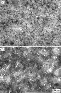
Fig.10 Metallographic morphologies of phosphate film formed at 50 ��, 10 min (a) and 80 ��, 10 min (b)
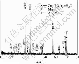
Fig.11 XRD pattern of phosphate film formed at 80 ��, 10 min
From Fig.10, there are many crystal particles on the film. At the higher temperature, the crystal is bigger. This is due to the reaction rate at higher temperature is larger and the crystal formed at higher temperature is bigger.
Fig.11 shows the XRD patterns of the phosphate film formed at 80 ��, 10 min. It can be seen that there are three phase components in the phosphate film. The ��-Mg and ��-Al12Mg17 are two phases in the microstructure of AZ31. ��- Mg is a solid solution of Mg- Zn-Al with the same crystal structure of pure magnesium. The ��-Al12Mg17 is an intermetallic phase containing more than 40% aluminium. The XRD patterns show that the film in this experiment mainly consists of hopeite (Zn3(PO4)2?xH2O).
4 Conclusions
1) It is possible to form a well-crystallized zinc phosphate layer on magnesium alloy AZ31 in the phosphating solution.
2) There is an optimum time in the phosphating process. At 50 ��, the optimum phosphating time is 20 min and the optimum phosphating time is 10 min at 80 ��.
3) The temperature has an obvious influence on the corrosion resistance of phosphate films. The film formed at high temperature(80 ��) owns higher corrosion resistance than the film formed at low temperature (50 ��).
4) In this phosphating bath, when the phosphating temperature is 80 �� and the phosphating time is 10 min, the film has the highest anti-corrosion resistance, and the film consists of hopeite (Zn3(PO4)2��xH2O).
References
[1] GRAY J E, LUAN B. Protective coatings on magnesium and its alloys��a critical review[J]. J Alloys Compd, 2002, 336: 88-113.
[2] AVEDESIAN M M, BAKER H (Eds.). Magnesium and Magnesium Alloys [M]. ASM International, USA, 1999.
[3] ABBAS G, LIU Z, SKELDON P. Corrosion behaviour of laser-melted magnesium alloys[J]. Applied Surface Science, 2005, 247: 347-353.
[4] ROSALBINO F, ANGELINI E, DE NEGRI S. Effect of erbium addition on the corrosion behaviour of Mg�CAl alloys[J]. Intermetallics, 2005, 13: 55-60.
[5] TIAN X B, WEI C B, YANG S Q. Corrosion resistance improvement of magnesium alloy using nitrogen plasma ion implantation[J]. Surface & Coatings Technology, 2005, 198: 454-458.
[6] TRUONG V T, LAI P K, MOORE B T, MUSCAT R F, RUSSO M S. Corrosion protection of magnesium by electroactive polypyrrole/paint coatings[J]. Synth Met, 2000, 110: 7-15.
[7] YFANTIS A, PALOUMPA I, SCHMEIBER D, YFANTIS D. Novel corrosion-resistant films for Mg alloys[J]. Surf Coat Technol, 2002, 151/152: 400-404.
[8] CHIU L H, CHEN C C, YANG C F. Improvement of corrosion properties in an aluminum-sprayed AZ31 magnesium alloy by a post-hot pressing and anodizing treatment[J]. Surface & Coatings Technology, 2005, 191: 181-187.
[9] DABALA M, BRUNELLI K, NAPOLITANI E, MAGRINI M. Cerium-based chemical conversion coating on AZ63 magnesium alloy[J]. Surface and Coatings Technology, 2003, 172: 227-232.
[10] RUDD A L, BRESLIN C B, MANSFELD F. The corrosion protection afforded by rare earth conversion coatings applied to magnesium[J]. Corrosion Science, 2000, 42: 275-288.
[11] BRUNELLI K, DABALA M, CALLIARI I, MAGRINI M. Effect of HCl pre-treatment on conversion resistance of cerium-based conversion coatings on magnesium and magnesium alloys[J]. Corrosion Science, 2005, 47: 989-1000.
[12] UMEHARA H, TAKAYA M, TERAUCHI S. Chrome-free surface treatments for magnesium alloy[J]. Surface and Coatings Technology, 2003, 169-170: 666-669.
[13] Chong K Z, Shih T S. Conversion-coating treatment for magnesium alloys by a permanganate-phosphate solution[J]. Materials Chemistry and Physics, 2003, 80: 191-200.
[14] KOUISNIA L, AZZI M, ZERTOUBI M, DALARD F, MAXIMOVITCH S. Phosphate coatings on magnesium alloy AM60 (part 1): study of the formation and the growth of zinc phosphate films[J]. Surface & Coatings Technology, 2004, 185: 58-67.
[15] KOUISNIA L, AZZI M, MAXIMOVITCH S. Phosphate coatings on magnesium alloy AM60 (part 2): Electrochemical behaviour in borate buffer solution[J]. Surface & Coatings Technology, 2005, 192: 239-246.
[16] CHENG Ying-liang, ZHANG Zhao, CAO Fa-he, LI J F, ZHANG J Q, WANG J M, CAO C N. A study of the corrosion of aluminum alloy 2024-T3 under thin electrolyte layers[J]. Corrosion Science, 2004, 46: 1649-1667.
[17] LIU Y K, CHENG Y L, ZHANG Z, WANG H M, CHEN Z H, WU Y M. Anti-corrosion properties of Ni-P alloy deposits prepared from electrolytes containing Na H2PO2��H2O[J]. The Chinese Journal of Nonferrous Metals, 2005, 15: 1642-1647. (in Chinese)
Foundation item: Project(05GK1006-1) supported by Hunan Province, China
Corresponding author: CHENG Ying-liang; Tel: +86-13036798588; E-mail: deepblacksea@163.com
(Edited by YANG Bing)
Abstract: Zinc phosphate films were formed on AZ31 magnesium alloy by immersing into a phosphatation bath to enhance the corrosion resistance of AZ31. Different films were prepared by changing the processing parameters such as immersing time and temperature. The corrosion protection of the coatings was studied by electrochemical measurements such as electrochemical impedance spectroscopy, potentiodynamic polarization curves, and the structure of the films were studied by metalloscopy and X-ray diffraction (XRD). The results show that, the film formed at 80 ��, 10 min has the highest corrosion resistance. The XRD patterns show that the film consists of hopeite (Zn3(PO4)2��xH2O).
