
J. Cent. South Univ. (2012) 19: 2348-2353
DOI: 10.1007/s11771-012-1281-1![]()
Longitudinal forces of continuously welded track on high-speed railway cable-stayed bridge considering impact of adjacent bridges
DAI Gong-lian(������), YAN Bin(�Ʊ�)
Department of Civil Engineering, Central South University, Changsha 410075, China
? Central South University Press and Springer-Verlag Berlin Heidelberg 2012
Abstract:
A proven beam-track contact model was used to analyze the track-structure interaction of CWR (continuously welded track) on bridge. Considering the impact of adjacent bridges, the tower-cable-track-beam-pier-pile finite element model of the cable-stayed bridge was established. Taking a bridge group including 40-32 m simply-supported beam and (32+80+112) m single- tower cable-stayed bridge and 17-32 m simply-supported beam on the Kunming-Shanghai high-speed railway as an example, the characteristics of CWR longitudinal force on the cable-stayed bridge were studied. It is shown that adjacent bridges must be considered in the calculation of the track expansion force and bending force on cable-stayed bridge. When the span amount of adjacent bridges is too numerous, it can be simplified as six spans; the fixed bearing of adjacent simply-supported beams should be placed on the side near the cable-stayed bridge; the track expansion device should be set at the bridge tower to reduce the track force near the bridge abutment.
Key words:
high-speed railway; continuously welded track; cable-stayed bridge; simply-supported beam��
1 Introduction
The continuously welded rail (CWR) on the bridge is different from the one on the roadbed, and its track is not only affected by temperature force, but also affected by the additional longitudinal forces on the bridge. Its transmission rule and distribution were extensively studied [1-8]. The 2D model was more used in the existing studies [3-5], but it was difficult to consider the spatial effect of single-track fracture in the 2D model; some models without considering the impact of the adjacent bridges were so simplified that larger errors were brought about [5-6]. Some models without considering the pier and pile foundation had some limitations to simulate the track-structure interaction [6]. Up to now, few study has been involved in the special bridge of the high-speed railway cable-stayed bridge.
Based on previous studies, the cable-stayed bridge space model of the high-speed railway was established with considering the adjacent bridges, pier and pile foundation, and the track spatial location. Taking a bridge group on the Kunming-Shanghai high-speed railway, including 40-32 m simply-supported beam and (32+80+112) m single-tower cable-stayed bridge and 17-32 m simply-supported beam as a project case, the characteristics of the CWR longitudinal force distribution on the cable-stayed bridge were studied and the impact of the parameters of adjacent bridges was discussed. The recommendations of the simplified method and the design parameter values were put forward.
2 Track-structure interaction model of cable-stayed bridge
The beam element with rigid elements was used to simulate the bridge. Assuming that the horizontal and vertical relative displacement did not occur between track and bridge, the nonlinear spring was used to simulate the line resistance, and outside the bridge, 250 m embankment track was established to reduce the influence of boundary conditions [4]. This model was used to calculate the track bending force of single-line 50 m simply-supported beam, and compared with the example of the experimental validation in Ref. [8]. The difference between them was less than 2%, indicating that the model could correctly simulate the track- structure interaction.
In order to truly simulate the spatial location of the track and the cable of the cable-stayed bridge, the beam element with the rigid arm was used to simulate the main beam, the bar element used to simulate the cable and its geometric nonlinearity was corrected [9-10], and the initial stress was simulated by applying the initial strain. In the simulation of the boundary condition, the longitudinal, vertical and horizontal displacements were constrained by the fixed bearing. Considering the friction resistance of the movable bearing having less impact on the track-structure interaction [4, 6], the longitudinal stiffness of the movable bearing was set to be 0. The equivalent stiffness matrix of the pile group foundation was calculated, and six freedom degrees of the spring were used to simulate the pile group foundation. The beam element was used to simulate the bridge pier by the actual situation. At each end of the bridge group, 250 m track on roadbed was established to reduce the impact of the boundary condition on the results.
The bridge was located in Changsha on the Shanghai-Kunming high-speed railway crossed by the Wuhan-Guangzhou high-speed railway. To minimize the impact of construction and maintenance on the existing high-speed railway, at the place across the Wuhan- Guangzhou high-speed railway, the swing cable-stayed bridge plan of the prestressed concrete was used with tower height of 51.8 m and the span arrangement of (32+ 80+112) m, and both beam and tower were consolidated with a single-tower and double-cable planes. 40-32 m simply-supported T-shape beam and (32+80+112) m single-tower cable-stayed bridge and 17-32 m simply- supported T-shape beam were used in the final plan of the bridge group, as shown in Fig. 1.
The single ballast track was laid down on the bridge, and U-shape section was adopted for the main beam. The bridge deck width was 6.6 m and the height was 4 m on the left of the bridge tower, 3.5 m on the right, as shown in Fig. 2. The section could not only prevent the ballast from dropping into the high-speed railway under the bridge, but also increase the torsional stiffness of the cable-stayed bridge [11]. In addition, the distance from the neutral axis of the U-shape beam to the track top was nearly half as small as the simply-supported beam, which could reduce the track bending force.
Both the static result of the track-structure interaction model and the data provided by the design institute were in good agreement. The difference between the bearing reaction force in the stage of the completed bridge and the computational model of the design institute was less than 8%, and the trend between the vertical deflection of the main beam and the computational result of the design institute was the same. Through the modal analysis of the model, the result was similar to the one in the ��train-bridge resonance report�� of the bridge. The first three frequencies of the ��report�� were 0.963 1, 1.002 5 and 1.358 6, respectively, and the first three frequencies were 0.930 3, 1.067 7 and 1.636 8 without considering the track of this model, with the first nine vibration modes being the same. It was proved that the quality and stiffness of the cable-stayed bridge model were accurately simulated.
The standard 32 m simply-supported T-shape beam designed for the high-speed railway was used for the simply-supported beam adjacent to the cable-stayed bridge.
3 Parameters of track-structure interaction model
The design parameters of the track-structure interaction model mainly included the longitudinal resistance, load mode, increasing-temperature, and so on.
BOINDIA et al [5] and GUANG et al [8] fitted the relation curve between the longitudinal resistance of the ballasted track and relative displacement through experiments. The constant resistance models were used in ��China CWR Interim Regulations 2003�� [12] and the ��Japanese Shinkansen Specification�� [13]. The ideal elastic-plastic models were used in ��German Standard�� [14] and ��2008 China Code for CWR Design (draft)�� [15]. After comparing various resistance models, it was found that these models were not very different in calculating the bending force, but when the expansion force was calculated with the constant resistance model, its result was so low that the design led to insecurity. While analyzing the longitudinal force, the model provided by Ref. [15] was used to simulate the line resistance in this work:
Vertical no-load
Vertical no-load
 (1)
(1)
where r is the longitudinal resistance, kN/m per line; u is the relative longitudinal displacement of the beam-track, mm. When the track fracture occurs, the relative displacement is much larger than 2 mm due to the occurrence of the beam-track slipping. So the constant resistance r=30 kN/m per line was used to calculate the fracture track force.
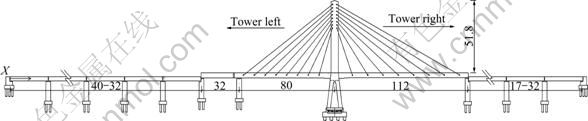
Fig. 1 Spans arrangement of cable-stayed bridge on Kunming-Shanghai high-speed railway (Unit: m)
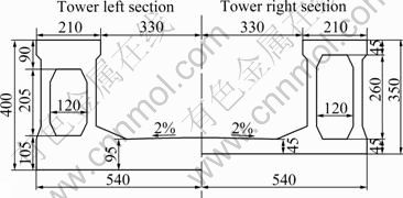
Fig. 2 U-shape section of cable-stayed bridge (Unit: cm)
In order to simplify the calculation of track flexural force, the live load was calculated in accordance with 0.8UIC uniformly distributed live load [4]. The load length was 200 m [16], and 0.25 was taken according to Ref. [4] for the braking force ratio while the train braking on the bridge.
In Ref. [6], it was recommended that the track bending force was calculated according to the daily temperature difference of the beam. In the ��German Standard��, it was calculated according to the 30 �� increasing-temperature of the beam. In Ref. [15], the increasing or reducing temperature of the ballasted track concrete beam was advised. It was noted that there was much controversy in the current values ??of the beam increasing-temperature, and the track expansion force was calculated when the beam temperature changed from -30 �� to 30 ��.
4 Impact of adjacent bridges on track longitudinal force of cable-stayed bridge
4.1 Influence and simplification of adjacent bridges
The bridge group was 40-32 m simply-supported beam on the left of the cable-stayed bridge and 17-32 m simply-supported beam on the right. Assuming that the bearing arrangement plans of the simply-supported beam were the same on both sides, the fixed bearing was on the left and the movable bearing was on the right.
While calculating the beam increasing-temperature from -30 �� to 30 ��, the track expansion force extremum with considering the adjacent bridges was compared with the results without considering the adjacent bridges, as shown in Fig. 3.
The relation between the beam temperature and track expansion force is linear. When the track temperature increases, the maximum pressure with considering the adjacent bridges model is about 1.2 times as large as the one without considering the adjacent bridges model. Therefore, the impact of the adjacent bridges must be considered.
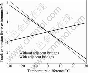
Fig. 3 Track expansion force comparison considering and without considering adjacent bridges
The computed result of the track expansion forces is shown in Fig. 4 when the increasing-temperature of the cable-stayed bridge and simply-supported beam is 15 ��.
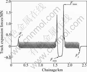
Fig. 4 Track expansion force of beam increasing-temperature of 15 ��
To examine the impact of span number on both sides of the cable-stayed bridge on the longitudinal forces of CWR on the cable-stayed bridge, 1-9 span simply-supported beams were separately established on both sides of the cable-stayed bridge, and the relative error between the four key positions (see Fig. 4) of the track and the data in reality was extracted in each model. The relative errors are shown in Fig. 5.
When the span amount on both sides of the cable-stayed bridge goes up to four, it is found that there is little difference between its value and the value under the actual situation. When the span number on both sides is more than six, the track expansion force extremum under the actual situation could be completely simulated. The rule is very close to the result in Ref. [4]. So, when the span amount on both sides is more than six, in order to reduce the consumption of the computing resources, six span simply-supported beams could be respectively established on both sides of the cable-stayed bridge for the calculation of the track longitudinal force.
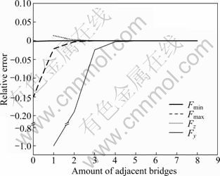
Fig. 5 Track expansion force relative error considering adjacent bridge span amount
4.2 Comparison between bearing arrangement plans of adjacent bridges
In order to compare the impact of bearing arrangement plans of adjacent simply-supported beams on track longitudinal force of the cable-stayed bridge, the following plans (as shown in Table 1) were calculated.
Table 1 Bearing arrangement plans of adjacent simply- supported beams
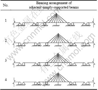
The four plans were used to calculate the track
expansion force of the beam increasing-temperature of 15 �� and the result is shown in Fig. 6. Among them, the track expansion force in Plan 3 is the least, and its maximum tension is 1 360.4 kN, only 70% of other plans. The extremum at the simply-supported bridge abutment is also smaller, only 37% of Plans 1 and 4. In addition, it is shown by the numerical experimental results that the bending force in the four plans is very close under the full span load, and those of Plans 3 and 1 are slightly smaller. Assuming that the track is broken at the right end of the cable-stayed bridge beam, the break-joint values produced in Plans 2 and 3 are slightly smaller. Taking all into account, it is recommended that Plan 3 is used as the arrangement plan of the adjacent bridges.
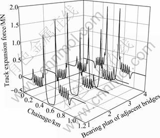
Fig. 6 Impact of bearing arrangement plans of adjacent simply- supported beams on track expansion force
4.3 Impact of adjacent bridges on braking and bending force
To compare the impact of the simply-supported beams on both sides of the cable-stayed bridge on the track bending force, the load mode of the influence line is used to calculate the envelope diagram of the maximum bending force. The result is shown in Fig. 7.

Fig. 7 Comparison of impact on track bending force considering and without considering adjacent structures
It is found through the computation that larger bending forces of track occur at both ends of the cable-stayed bridge while considering the adjacent structures. For example, at the right end of the cable-stayed bridge, the result considering the adjacent structures is about 2 times as large as the value without considering the adjacent structures. Therefore, while calculating the bending force of CWR on the cable-stayed bridge, the impact of the adjacent bridges must be considered.
As the train brakes (or starts) on the bridge to produce the braking force, the bending force is certainly accompanied. Taking into account that the bending force distribution of such special bridges as the cable-stayed bridge is complex, it is proposed to calculate the working condition affected by the braking and bending force at the same time. The result shows that the existence of the simply-supported beam has small impact on the track longitudinal force of the cable-stayed bridge, but the peak values of the braking and bending force have a slight offset in the forward direction of the train.
4.4 Broken track force considering adjacent bridges
Considering that the track expansion forces of the cable-stayed bridge are larger in the center and at both ends, it is assumed that the single-track is broken separately at the left end, in the center and at the right end of the cable-stayed bridge. The result of the track longitudinal displacement is shown in Fig. 8.
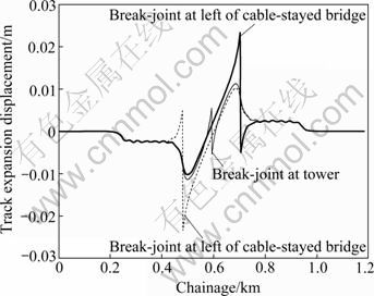
Fig. 8 Impact of different break-joint positions on track displacement
When the break-joint occurs at both ends of the bridge, the break-joint values ??are similar and larger, about 2.8 cm. If the break-joint occurs at the bridge tower, the break-joint values are smaller, 1.0 cm or so. In addition, the track break-joint at the bridge tower would greatly reduce the relative beam-track displacement at both ends. So, for the single-tower cable-stayed bridge of tower-beam consolidation, the track expansion device could be set at the bridge tower if necessary.
The adjacent bridges have very small impact on the break-joint value, which could be ignored.
5 Conclusions
1) The model and the parameters can be used to analyze the track-structure interaction of the high-speed railway cable-stayed bridge.
2) While calculating the track expansion force on the high-speed railway cable-stayed bridge, the impact of adjacent bridges must be considered. When the amount of the adjacent simply-supported bridge spans is more than six spans, it can be simplified by six spans.
3) The fixed bearing is placed near the cable-stayed bridge side to reduce the track force when choosing the bearing arrangement of the simply-supported beam at both ends of the cable-stayed bridge.
4) The adjacent bridges have large impact on the track maximum bending force.
5) If the track expansion device needs to be set on the high-speed railway cable-stayed bridge, it is recommended to set it at the bridge tower so as to effectively reduce the track force near the bridge abutment. The adjacent bridges have very small impact on the break-joint value.
References
[1] RUGE P, BIRK C. Longitudinal forces in continuously welded rails on bridge decks due to nonlinear track�Cbridge interaction [J]. Computers & Structures, 2007, 85(4): 458-475.
[2] YAN Bin, DAI Gong-lian, ZHANG Hua-ping. Beam-track interaction of high-speed railway bridge with ballast track [J]. Journal of Central South University, 2012, 19(5): 1447-1453.
[3] READ D, LOPRESTI J. Management of rail neutral temperature and longitudinal rail forces [J]. Railway Track and Structures, 2005, 101(8): 18-19.
[4] BU Yi-zhi. Research on the transmission mechanism of longitudinal force for high-speed railway bridges [D]. Chengdu: Southwest Jiaotong University, 1998. (in Chinese)
[5] BIONDIA B, MUSCOLINOB G, SOFIB A. A substructure approach for the dynamic analysis of train�Ctrack�Cbridge system [J]. Computers & Structures, 2005, 83(11): 2271-2281.
[6] XU Qing-yuan, ZHANG Xu-jiu. Longitudinal forces characteristic of Bogl longitudinal connected ballastless track on high-speed railway bridge [J]. Journal of Central South University: Science and Technology, 2009, 40(2): 526-532. (in Chinese)
[7] YAU J D. Response of a train moving on multi-span railway bridges undergoing ground settlement [J]. Engineering Structures, 2009, 31(9): 2115-2122.
[8] GUANG Zhong-yan, GAO Hui-an. Railway CWR [M]. Beijing: China Railway Press, 2005: 38-62. (in Chinese)
[9] YAN Bin, DAI Gong-lian. CWR longitudinal force of cable-stayed bridge on high-speed railway [J]. Journal of the China Railway Society, 2012, 34(3): 83-87. (in Chinese)
[10] THAI Huu-tai, KIM Seung-eoc. Nonlinear static and dynamic analysis of cable structures [J]. Finite Elements in Analysis and Design, 2011, 47(3): 237-246.
[11] JIANG Peng. Interaction between girder and rail of rail transit viaduct with U-shape girder [D]. Shanghai: Tongji University, 2008. (in Chinese)
[12] 2003-205 Railway Construction. Interim provisions of CWR design on newly built railway bridge [S]. Beijing: China Railway Press, 2003. (in Chinese)
[13] FREIRE A M S, NEGR?O J H O, LOPESB A V. Geometrical nonlinearities on the static analysis of highly flexible steel cable-stayed bridges [J]. Computers & Structures, 2006, 84(31/32): 2128-2140.
[14] German Standard DS899/59, Special procedures on railway Shinkansen bridge [S]. Bridge Research Institute of Railway Bridge Authority, 1991
[15] Code for railway CWR design (draft) [S]. Beijing: Institute of Economic Planning Ministry of Railways, 2008. (in Chinese)
[16] HU Nan, DAI Gong-lian. The introduction of high-speed railway bridges in Wuhan-Guangzhou passenger line [C]// 33rd IABSE Symposium 2009 Bangkok. Bangkok: IABSE, 2009: 62.
(Edited by HE Yun-bin)
Foundation item: Project(51178469) supported by the National Natural Science Foundation of China
Received date: 2011-06-25; Accepted date: 2011-10-09
Corresponding author: YAN Bin, PhD Candidate; Tel: +86-13787799105; E-mail: zhixu1984@gmail.com
Abstract: A proven beam-track contact model was used to analyze the track-structure interaction of CWR (continuously welded track) on bridge. Considering the impact of adjacent bridges, the tower-cable-track-beam-pier-pile finite element model of the cable-stayed bridge was established. Taking a bridge group including 40-32 m simply-supported beam and (32+80+112) m single- tower cable-stayed bridge and 17-32 m simply-supported beam on the Kunming-Shanghai high-speed railway as an example, the characteristics of CWR longitudinal force on the cable-stayed bridge were studied. It is shown that adjacent bridges must be considered in the calculation of the track expansion force and bending force on cable-stayed bridge. When the span amount of adjacent bridges is too numerous, it can be simplified as six spans; the fixed bearing of adjacent simply-supported beams should be placed on the side near the cable-stayed bridge; the track expansion device should be set at the bridge tower to reduce the track force near the bridge abutment.
