

Contrast of FEM and FVM in simulation of complex aluminum extrusion
LI Da-yong(�����), ZHOU Fei(�� ��), CHANG Qun-feng(��Ⱥ��), PENG Ying-hong(��ӱ��)
School of Mechanical Engineering, Shanghai Jiao Tong University, Shanghai 200240, China
Received 28 July 2006; accepted 15 September 2006
Abstract:
Extrusion is the key technology to manufacture aluminum profiles and involves complicate metal deformation coupled with temperature changes. The choice of numerical technique plays an important role and is related to the accuracy and effectiveness of extrusion process analyses. In this paper, the extrusion processes of two complex aluminum profiles are simulated with FEM and FVM respectively. The merit and disadvantage of these two methods are analyzed. The finite element method exhibits higher calculation efficiency in the simulation of a lock catch extrusion process. However, due to frequent rezoning in simulation of complex extrusion process, sharp distortion of finite element mesh can decrease computational accuracy. Therefore the volume loss in FEM simulation is larger than that in FVM simulation by five percent. Based on Euler description, the finite volume method employs structured element mesh covering entire material flowing area, which makes it more robust in the simulation of complicate extrusion process. The deformation configuration with FVM is much smoother than that with FEM in the extrusion simulation of a thin-walled aluminum profile, although FVM requires more computation time.
Key words:
aluminum profile; extrusion; numerical simulation; finite element method (FEM); finite volume method (FVM);
1 Introduction
Extrusion is widely applied in a variety of industries, such as aviation, architecture. In the extrusion of complex aluminum profiles, extremely complicate deformation coupled with heat conduction occurs, which is difficult to be measured through experiment. Therefore, numerical simulation of aluminum profile extrusion has been playing an increasing important role in extrusion die design and process optimization.
Two techniques, the finite element method (FEM) and the finite volume method (FVM), are available for aluminum profile extrusion simulation. The finite element method has been extensively used in the simulation of metal forming, including extrusion, in last several decades. Based on Lagrange description, FE meshes change with the deformation configuration of material. Therefore, mesh rezoning is inevitable during simulation of a complicate extrusion process. PENG et al[1] have studied CONFORM continuous extrusion forming process using rigid plasticity finite element method. LOF[2-3] has simulated the extrusion process of complex thin-walled aluminum sections with finite element method. To avoid using a large number of elements in the bearing part, an equivalent bearing model is assumed. PENG and SHEPPARD[4] have simulated a multi-hole die extrusion process using a commercial FEM code FORGE3 to study the influence of the number and the distribution of die holes on extrusion parameters. The finite volume method, which was mainly used in fluid analysis, has also been applied in metal forming simulation in recent years. VRIES and DING[5] have introduced the FVM simulation technology and its application in forging and extrusion simulation. CHUNG et al[6] have studied the effect of die geometry on the double shear extrusion by carrying out a 2D axi-symmetric finite volume method. ZHOU et al[7-8] have simulated the extrusion processes of complex aluminum profiles with 3D finite volume method. In FVM simulation, an Euler mesh frame is established in advance which covers initial and deformed area based on Euler description. Material flows through these Euler elements during metal deformation and the meshes keep fixed.
In this paper, after summarization of the theoretical background of the finite element method and the finite volume method, the extrusion processes of two complicate aluminum profiles are simulated with these two simulation techniques and the results are compared with each other. The advantages and inconveniences of these two techniques in aluminum extrusion simulation are analyzed to provide an instruction for the selection of simulation techniques in aluminum extrusion process analysis.
2 Summary of theoretical background of FEM and FVM
FEM. Based on Lagrange description, the finite element method employs non-structured meshes, which change along with metal deformation process. The variational principle for a rigid/rigid-viscous plasticity problem is[9]
![]() (1)
(1)
where V is material volume; Sr is the area; Fi is external force; a is penalty multiplier; ![]() is Cauchy stress and
is Cauchy stress and ![]() is train rate.
is train rate.
After finite element discretization, the following equation can be obtained and solved by Newton-Raphson method:
![]() (2)
(2)
where [S] is stiffness matrix; ![]() is displacement increment;
is displacement increment; ![]() is nodal force vector.
is nodal force vector.
FVM. Based on Euler description, the finite volume method employs structured meshes which keep fixed during deformation process. Material flows through these Euler elements with the transfer of mass, momentum and energy. During metal flow process, the following control equations should be satisfied[10].
Mass conservation equation:
![]() �� ����(3)
�� ����(3)
Momentum conservation equation:
![]() (4)
(4)
Energy conservation equation:
![]() (5)
(5)
State equation:
![]() (6)
(6)
where V is element volume; S is element area; ni is the unit normal vector of element surface; ![]() ,
,![]() ,
,![]() , E are material density, velocity vector, pressure and internal energy respectively.
, E are material density, velocity vector, pressure and internal energy respectively.
The above control equations can be expanded with Staggered Grid[11], and then solved with Runge-Kutta time-integration algorithm[12], through which various physical variables can be obtained.
3 Contrastive simulation of extrusion process by FEM and FVM
3.1 Simulation of lock catch
Fig.1 shows a flat die for a lock catch made of 6061 aluminum alloy. The dimension of the cylindrical billet is d 78 mm��13 mm. The total extrusion ratio is 38.19. The speed of extrusion punch is 10 mm/s along Z direction and the stroke is 7.5 mm. The initial temperatures of billet and die are 480 �� and 460 �� respectively. The friction coefficient between billet and tool is 0.6.
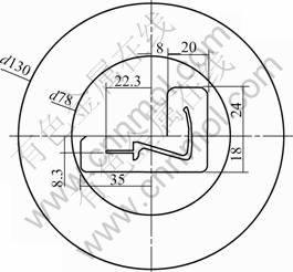
Fig.1 Extrusion die for lock catch
In FEM simulation, the billet is divided to 29 284 tetrahedron elements with 6 671 nodes. The time increment is set as 0.01 s for each FEM iteration step. When the metal flows through die land, the mesh has to be refined to continue the simulation. After the first mesh refinement, the element number reaches 31 848 and the node number is 7 972. The whole simulation process takes 28 h. 36 times mesh rezoning happens, which takes most of the computation time.
In FVM simulation, a area of 84 mm��84 mm��120 mm(in Z direction) is discretized into 3 920 000 Euler elements with size of 0.6 mm. The total computation time is up to 34 h.
Fig.2 shows the comparison of deformation configurations by FEM and FVM. At the pre-forming stage, little difference is shown between the results by the two methods. The non-smooth of profile surface in FEM simulation results from the mesh distortion during rezoning; while the reason for non-smooth in FVM simulation is element size is not small enough due to limitation of computer memory. Fig.3 and Fig.4 shows the deformation process and velocity distribution during extrusion calculated by the two methods. The end velocity is 295.8 mm/s in FEM simulation and 311.8 mm/s in FVM simulation. Since the velocity of extrusion punch is 10 m/s and extrusion ratio is 38.19, the theoretical end velocity should be 381.9 mm/s. Therefore the volume loss in FEM simulation is 23%, larger than 18% in FVM simulation by 5%.

Fig.2 Comparison of deformation configuration by two methods: (a) FEM result; (b) FVM result
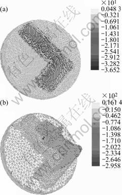
Fig.3 Deformation process and velocity distribution calculated by FEM
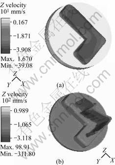
Fig.4 Deformation process and velocity distribution calculated by FVM
3.2 Simulation of window component
Fig.5 shows the schematic drawing of another aluminum profile whose relative thickness is very small. Its thickness is 1.4 mm and length is 80 mm. The material is 6061 aluminum alloy. The diameter of billet is 120 mm. The billet and die are heated to 480 �� and 460 �� respectively before extrusion. The friction coefficient is 0.4. Fig.6 shows the configuration when punch stoke reaches 7.05 mm. Due to the relative thin thickness, the finite element mesh configuration is very easy to be distorted during rezoning, as shown in Fig.6(a). In contrast, the finite volume method has advantage in simulating the thin thickness problem, and can obtain good deformation configuration, as shown in Fig.6(b).
Fig.7 shows the deformation process and equivalent stress distribution during extrusion simulation. At the pre-forming stage, a stagnant zone appears under the press of extrusion container and die face. The stress in this stagnant zone is relatively high. After metal flows into pre-forming die cavity, the highest stress appears in the die land area because the narrow die land makes metal flow difficult at the shape forming stage. Therefore the wear at the die land area is the most severe.

Fig.5 Drawing of window component

Fig.6 Comparison of deformation configuration by two methods: (a) FEM result; (b) FVM result

Fig.7 Deformation process and effective stress distribution calculated by FVM
4 Conclusions
1) FEM shows more computation efficiency in the simulation of extrusion process of aluminum profiles. However, its accuracy is impaired by frequent mesh rezoning in shape forming stage.
2) FVM exhibits more robustness in simulation of complex profiles since no rezoning is needed. It is the better choice for simulation of extrusion of thin-walled product. In order to obtain good surface appearance, more refined Euler mesh that covers both initial and deformation areas is required, and then more computation time and computer memory is needed.
3) If the FEM and FVM can be combined by using FEM in pre-forming stage and FVM in shape forming stage, the efficiency and robustness of simulation of complex aluminum profile extrusion processes can be both improved.
References
[1] PENG Y H, PENG D S, ZUO T Y. Simulation of CONFORM continuous extrusion forming process using rigid plasticity finite element method[J]. The Chinese Journal of Nonferrous Metals, 1993, 3(4): 42-47.
[2] LOF J. Elasto-viscoplastic FEM simulations of the aluminum flow in the bearing area for extrusion of thin-walled sections [J]. J Mater Process Technol, 2001, 114: 174-183.
[3] LOF J. FEM simulation of the extrusion of complex thin-walled aluminum sections[J]. Journal of Mater Process Technol, 2002, 122: 344-354.
[4] PENG Z, SHEPPARD T. Simulation of multi-hole die extrusion [J]. Material Science and Engineering A, 2004, 367: 329-342.
[5] VRIES E D, DING P. Simulation of 3D forging and extrusion problems using a finite volume method[A]. Proceedings of 17th MSC Japan Users Conference[C]. Japan: MSC Software Company, 1999. 155-161.
[6] CHUNG S W, Kim W J, HIGASHI K. The effect of die geometry on the double shear extrusion by parametric FVM simulation[J]. Scripta Materialia, 2004, 51: 1117-1122.
[7] ZHOU F, SU D, PENG Y H. Key technologies for simulation of metal forming process with fitnite volume method[J]. Journal of Shanghai Jiao Tong University, 2003, 37(2): 149-152.
[8] ZHOU F, SU D, PENG Y H, RUAN X Y. Simulation of aluminum material extrusion process with finite volume method[J]. The Chinese Journal of Nonferrous Metals, 2003, 13(2): 65-70.
[9] KOBAYASHI S, Oh S I, ALTAN T. Metal forming and the Finite Element Method[M]. New York: Oxford University Press, 1989: 12-49.
[10] VERSTEEG H K, MALASEKERA W. An Introduction to Computational Fluid Dynamics��the Finite Volume Method[M]. England: Longman Group Ltd., 1995: 5-137.
[11] SLAGTER W J, FLORIE C J L, VENIS A C J. Advances in 3D forging process modeling[J]. Journal of Computational Physics, 1991, 92: 82-105.
[12] SHEN Y H, LIANG Z Z, XU L H. Applied Mathematic Manual [M]. Beijing: Science Press, 2001. 726-732.
(CHEN Ai-hua)
Foundation item: Projects(0452nm034, 0552nm041) supported by the Science and Technology Committee of Shanghai, China
Corresponding author: LI Da-yong; Tel: +86-21-34206313; E-mail: sjtukbe@126.com
