
J. Cent. South Univ. (2016) 23: 2695-2704
DOI: 10.1007/s11771-016-3331-6

Fractured rock mass hydraulic fracturing under hydrodynamic and hydrostatic pressure joint action
ZHOU Zhong(����), YANG Hao(���), WANG Xiang-can(�����), ZHANG Qi-fang(���뷼)
School of Civil Engineering, Central South University, Changsha 410075, China
 Central South University Press and Springer-Verlag Berlin Heidelberg 2016
Abstract:
According to the stress state of the crack surface, crack rock mass can be divided into complex composite tensile-shear fracture and composite compression-shear fracture from the perspective of fracture mechanics. By studying the hydraulic fracturing effect of groundwater on rock fracture, the tangential friction force equation of hydrodynamic pressure to rock fracture is deduced. The hydraulic fracturing of hydrostatic and hydrodynamic pressure to rock fracture is investigated to derive the equation of critical pressure when the hydraulic fracturing effect occurs in the rock fracture. Then, the crack angle that is most prone to hydraulic fracturing is determined. The relationships between crack direction and both lateral pressure coefficient and friction angle of the fracture surface are analyzed. Results show that considering the joint effect of hydrodynamic and hydrostatic pressure, the critical pressure does not vary with the direction of the crack when the surrounding rock stationary lateral pressure coefficient is equal to 1.0. Under composite tensile-shear fracture, the crack parallel to the direction of the main stress is the most prone to hydraulic fracturing. Under compression-shear fracture, the hydrodynamic pressure resulting in the most dangerous crack angle varies at different lateral pressure coefficients; this pressure decreases when the friction angle of the fracture surface increases. By referring to the subway tunnel collapse case, the impact of fractured rock mass hydraulic fracturing generated by hydrostatic and hydrodynamic pressure joint action is calculated and analyzed.
Key words:
hydraulic fracturing; hydrodynamic pressure; subway tunnel; collapse mechanism��
1 Introduction
Hydraulic fracturing is a physical phenomenon wherein cracks occur and expand in fracture rock mass because of the increase in water pressure. Hydraulic fracturing pertains to the occurrence of intermittent rock fractures (or voids) that extend and are interconnected; these fractures are further extended at high head pressure.
Hydraulic fracturing is a mature technology in in situ stress measurements in geotechnical engineering; this technology is applied to seepage curtain in hydropower projects, foundation reinforcement treatment, underground grouting, and geothermal exploitation [1-3]. However, hydraulic fracturing also results in disasters, such as numerous instances of sudden gushing water inrush during tunnel construction and operation. In subway tunnel construction, collapse is the most common and serious security incident; it is a serious threat to humans and their property. Research on the collapse mechanism remains in the managing after tunnel collapse stage, and the general rule is yet to be established [4-5]. Therefore, in-depth study of the mechanism of tunnel collapse is urgent and extremely valuable for fast and safe tunnel construction.
The mechanism of hydraulic fracturing was investigated by many researchers. HUBBERT and WILLIS [6] studied the hydraulic fracturing mechanism by using assumed plane strain and assuming that rock mass is a homogeneous, isotropic, elastic medium that does not have permeability. Hence, it is not vulnerable to drilling rupture because the hoop stress reaches the hole tensile strength of the rock. Hydraulic fracturing field test results indicated that regardless of whether the liquid can penetrate the rock, a cracked surface is always perpendicular to the minor principal stress directions. NOBARI et al [7] studied embankment dam hydraulic fracturing conditions. They employed hollow cylindrical specimens and conducted an indoor hydraulic fracturing test with a sandy clay specimen. However, their study only qualitatively described the relationship among hydraulic fracturing, effective stress, and seepage. DING and SUN [8] derived nonlinear elastic solutions for a thick-walled cylinder under steady flow, isotropic consolidation, and anisotropic consolidation and concluded that composite tensile-shear fracture damage cracks occur first at the hole inside the wall and then extend outward through the cracks cut through the wall. YANG et al [9] analyzed the rupture mechanism of hydraulic fracturing according to the wall stress distribution of the hole fracture segment with a tensile failure criterion and a Mohr-Coulomb criterion. They found that hydraulic fracturing has two fracturing modes: tensile and shear failure. ZHAN and CEN [10], by means of thick-walled cylinder hydraulic fracturing test specimens, proposed the mechanism of seepage force action and derived a stress distribution analytical solution for a thick-walled cylinder under steady seepage. They confirmed that hydraulic fracturing occurs in the inner wall of the ring crack when the damage stress reaches the ultimate tensile strength of the specimen. HUANG et al [11] addressed the problems of deep tunnel water gushing, analyzed the crack propagation mechanism at high water pressure, and revealed the cracked tensile fracture situation of single fractures. LI and REN [12] referred to the engineering approximation crack instability criterion to derive critical pressure computational equations for both complex composite tensile-shear fracture and composite compression-shear fracture in the compression-shear stress state. However, the compression-shear parameters need to be determined by a test. Therefore, the equation is complex. SHENG et al [13] studied the calculation of the stress intensity factor for various types of hydraulic pressure tunnels surrounding rock zone cracks (Type I failure) and analyzed the theoretical criterion of mixed-mode crack open-type hydraulic fracturing, water pressure, and fracture criterion for the calculation of the compression- shear fracture stress intensity factor.
Many researchers utilized limit analysis, limit equilibrium, and slip line methods to analyze the tunnel collapse failure mechanism, collapse scope, and collapse size. FRALDI and GUARRACINO [14-16] referred to the Hoek�CBrown failure criterion, utilized upper bound limit analysis method, deduced the theoretical equation of collapse scope and failure form of a rectangular tunnel, and analyzed the influence of different parameters on the scope of collapse. Thereafter, they extended this method to any geometric cross-section tunnel so that general equations for the collapse range of different section tunnels can be derived. YANG et al [17-20] adopted the Hoek�CBrown failure criterion, utilized the upper bound method of limit analysis, analyzed the surrounding rock stability of shallow tunnels and failure modes, established a limit analysis in geotechnical nonlinear theory, and theoretically derived ceiling solutions for the supporting force and scope and shape of tunnel collapse under pore water pressure. HUANG et al [11] referred to fracture mechanics theory, proposed the influence of hydraulic fracturing effect on groundwater tunnel collapse, analyzed the role of hydrostatic pressure in the expansion of rock fracture under high head pressure, and derived the theory of the surrounding rock crack opening degree by analyzing the expansion of rock crack. Cracks develop through the entire rock joint and damage the tunnel support structure, ultimately leading to the collapse of the tunnel. KAWAMOTO et al [21] adopted damage mechanics, obtained the damage evolution equation, and determined the constitutive relation of the anchored jointed rock. They used these to analyze the deformation behavior and stability of fractured rock mass tunnels.
Current studies on the mechanism of hydraulic fracturing do not consider the dynamic influence of water pressure. The real issue in rock engineering (underground tunnels, mines, rockfill dams, etc.) is often in non-steady seepage; often, unsteady seepage is more destructive and has a greater impact on hydraulic fracturing.
In the current work, theoretical equations of tangential drag force on a rock fracture wall caused by hydrodynamic pressure are derived according to the groundwater surrounding rock of hydraulic fracturing of the rock fracture effect. The water pressure value equation with regard to the critical fracture of the surrounding rock during hydraulic fracturing is derived in consideration of the hydrostatic and hydrodynamic pressure on the joint action of the surrounding rock hydraulic fracture. By referring to the Wuhan subway tunnel collapse case, the impact of fractured rock mass hydraulic fracturing generated by hydrostatic and hydrodynamic pressure joint action is calculated and analyzed.
2 Failure modes of fractured rock mass hydraulic fracturing
In fracture mechanics, the extension and deformation of a crack can be divided into the following three basic categories according to mechanical characteristics, as indicated in Fig. 1.
1) Tension open type (Type I): The crack formed by the tensile stress crack perpendicular to the surface and the crack surface results in crack opening displacement.
2) Slide open type (Type II): Shear stress on the crack plane perpendicular to the crack tip line forms a crack along the sliding direction of the shear stress.
3) Tear type (Type III): Shear stress on the crack plane parallel to the crack tip and a crack along the outer surface of the relative sliding form a crack.
The theory of fracture mechanics is mainly divided into two categories. The first category is the theory of fracture energy release rate. The second category is stress intensity factor fracture theory.
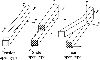
Fig. 1 Schematic of crack deformation
The first type of the energy release rate of fracture theory exports the appropriate fracture criterion from the point of view of the constant and conversion. The most important theories are energy release rate fracture theory, Orowan theory, and Griffith theory.
The second type of stress intensity factor fracture theory assumes that fracture of the component materials is mainly caused by expansion of the crack, which is determined by the fracture of the stress intensity factor. For Types I, II and III, crack stress intensity factor corresponding to the respective fracture criterion, the stress intensity factors of the three crack types are


 (1)
(1)
where ��, �� and �� are the geometry factors of types I, II and III crack; �� is the tensile stress of the crack surface; �� is the shear stress of the crack surface; and ��l is the shear stress crack of the outer surface.
The corresponding stress intensity factor fracture criteria are


 (2)
(2)
where KIc, KIIc and KIIIc are the fracture thresholds of KI, KII and KIII, respectively; they are the project material parameters, which are collectively called the fracture toughness of the material.
In the surrounding rock mass under initial stress and groundwater pressure, before tunnel excavation, initial stress in the fracture surface of the normal component in most cases closes the structure of the surface compression fracture. The groundwater head pressure in the fractured surface of the normal component causes expansion cracks to occur.
Before the tunnel is excavated, the hydrostatic pressure of a point in the surrounding rock mass is generally smaller than the stress. Under the effect of stress in the entire environment, hydraulic fracturing would generally not occur. At this time, the groundwater pressure reduces the effective stress of the surrounding rock mass.
After the completion of tunnel excavation, the surrounding rock mass is disturbed, and channel excretion for groundwater is provided, particularly when the groundwater is rich. The water gushing phenomenon occurs in the surrounding rock area, and the surrounding rock is affected by the high water pressure. The initial support cracks easily and is damaged. Cracks are likely to cause a hydraulic fracturing phenomenon under high water pressure, leading to the expansion of the cracks or creation of a new crack, enhancement of the connectivity between cracks, promotion of runoff circulation of groundwater, increase in the penetration of the surrounding rock and soil capacity, and acceleration of the destruction of the surrounding rock and soil.
3 Critical water pressure of hydraulic of fractured rock mass under influence of hydrodynamic and hydrostatic pressure joint action
When the fractured rock is filled with groundwater, the groundwater places hydrostatic pressure perpendicular to the fracture wall and hydrodynamic pressure parallel to the fracture wall. Hydrostatic pressure produces vertical displacement of the cracks in the surrounding rocks, so that cracks expand and deform; hydrodynamic pressure generates tangential thrust by the flow on the fissure wall to reduce the shear strength of the rock and soil. When fillers are placed in the cracks, the action of pore hydrodynamic pressure caused the fine particles in the rock and soil to move even to be carried out outside the rock and soil.
3.1 Derivation of tangential friction force equation of hydrodynamic pressure to rock fracture
Assumptions 1: The surrounding rock mass has a single crack whose width is uniform.
Assumptions 2: The crack surface is flat and has unlimited extension.
Assumptions 3: The length of the crack is far greater than its width.
Assumptions 4: The rock fracture wall is stationary.
The flat-shaped fissure flow diagram is shown in Fig. 2.
With the above assumptions and by using the hydrodynamic equation of motion and continuity equation, the following single wide flow and flow rate
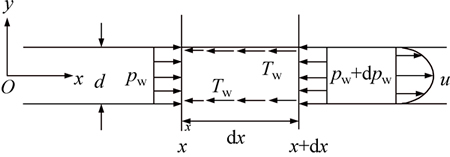
Fig. 2 Single fracture flow diagram
equations are obtained.
 (3)
(3)
 (4)
(4)
 (5)
(5)
 (6)
(6)
where d is the width of the fissure; ��w is the powered viscosity coefficient; Jf is the fissure in the direction of fluid along x hydraulic gradient; u is the flow rate of fluid along fissures x direction; pw is the fissure fluid pressure; and H is the hydraulic fluid head.
As shown in Eq. (4), flow rate u is parabolic distribution in the y direction but independent of the x coordinate, namely, in any x cross section, u has the same distribution.
As shown in Eq. (5), water pressure pw is independent of the y coordinate but dependent on the x coordinate, i.e., in any x cross section, pw distributions are the same. To crack walls, the direction of pw is perpendicular to the crack wall and plays an expansion role of fracture initiation.
1) When the fissure is not filled with soil, the drag force by water flow to the fractured wall is surface force. It is a reaction force of the fractured wall against the flow booster. Based on the principle of action and reaction, these two forces are equal in magnitude and opposite in direction. Therefore, the drag force of fracture flow can be determined by investigating the fissure fracture wall resistance to fluid flows.
In creating the laminar flow of liquid movement, adjacent shear stress and shear rate flow between the layers have a linear relationship as
 (7)
(7)
The fissure flow velocity relation equation is shown as
 (8)
(8)
Combining Eqs. (7) and (8) results in:
 (9)
(9)
where umax is the maximum flow rate of the midline of the fracture along the x direction and  is the average fracture flow rate along the direction of x.
2) When the fissure is filled with substances, permeate flow brings hydrodynamic pressure (permeate volume force) to the fracture filling substances. The submerged substances suffer from drag force along the flow direction, and the force is transmitted to the objects that come into contact. EVEET and LIU [22] studied a spherical and 2D cylinder (the axis perpendicular to the flow direction) by drag force, and the drag force to the submerged substances is calculated as
 (10)
(10)
where �� is the density of water, A is the projected area of the filling block perpendicular to the flow direction, u is the flow rate related to the filling block, CDis the drag force coefficient (mainly affected by aspect ratio �� which means the drag force coefficient varies in direct proportion to the aspect ratio of �� when the Reynolds number of object block shapes is Res>1000). When ��=1.0, CD=1.05; when �� approaches infinity, CD=2.05.
The seepage mode of rock mass fracture is filled with soil as seen in Fig. 3. The flow rate related to the filling block is equal to the flow average velocity  . The projected area of the filling block perpendicular to the flow direction is equal to 2ad which can be expressed by soil porosity n as
 (11)
(11)
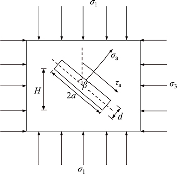
Fig. 3 Schematic of an ideal single crack force
The drag force on the block (filling soil) by the flow water is transmitted to the surface of the crack wall. Thus, drag force Tw on the surface of the crack wall is calculated as
 (12)
(12)
where n is the porosity of the filler soil and  is the average fluid velocity.
3) When fracture flow is sufficient to move the fracture gap filler as what usually occurs in the piping phenomenon, hydrostatic pressure pw to the wall of the crack is produced by mud mixed fluid as
 (13)
(13)
where ��fg is the mud fluid volume-weight.
As shown in Fig. 2, by using the hydrodynamics of the total flow volume equation to the fluid between section x to section x+dx in the x direction, it is deduced:
 (14)
(14)
where  is the average velocity of section x;
  is the average velocity of section x+dx; ��1is the momentum correction factor of section x; ��2 is the momentum correction factor of section x+dx; and ��Fxis the total force of dx fractured segment fluid direction along x.
The above analysis shows that u has the same distribution in both sections x and x+dx; therefore, the left side of Eq. (14) is equal to zero, that is
 (15)
(15)
According to Fig. 2, the suffered force in the x direction of the fluid between sections x and x+dx can be obtained as
 (16)
(16)
where Twis the fissure wall resistance to fluid flow.
By incorporating Eq. (16) into Eq. (15), it can be deduced.
 (17)
(17)
The drag force on the wall of the crack produces Twand it is obtained:
 (18)
(18)
where Jfis the fissure fluid hydraulic gradient along the x direction.
3.2 Hydraulic fracturing critical water pressure derivation
Fracture in the surrounding rock via the joint action of water pressure usually refers to the role of hydraulic fracturing. Hydraulic fracturing consumes much time and could have a serious impact on the project.
Hydraulic fracturing is when fractured (or void) rock mass expansion occurs at high head pressure; it refers to the expansion process or the formation of new cracks and fissures (or voids) owing to further opening. Therefore, a fracture mechanics model is established, as shown in Fig. 3. Analysis of the critical crack head pressure hydraulic fracturing effect is conducted with 2a as the crack length and d as the crack width.
As shown in Fig. 3, the flat slab is set to ��infinite��, the crack length is 2a, crack width is d, angle �� is between the direction of the crack and maximum principal stress ��1, and water pressure p in the crack is uniform. Elasticity theory shows that the water pressure on the crack of the rock includes hydrostatic and hydrodynamic force. Hydrostatic force affects normal effective stress crack, and dynamic hydraulic force influences crack tangential effective stress. Considering that hydrostatic pressure is applied perpendicular to the internal wall of fissures and hydrodynamic pressure was applied parallel to the walls of the crack, hydrodynamic pressure is the performance on the water drag force to the fissure wall, which suffers from crack normal stress ��a and shear stress ��a as
 (19)
(19)
 (20)
(20)
As shown in Fig. 3, normal stress ��a may be tensile or compression stress. When the hydraulic fracturing effect occurs, tensile-shear fracture failure results from tensile stress; compressive-shear fracture failure results from compressive stress.
3.2.1 Hydraulic splitting critical water pressure under tensile-shear state
According to fracture mechanics, when normal stress ��a is tensile stress, the crack extension issues are I-II tensile shear mixed-mode crack problems. For mixed-mode crack fracture criteria, such as maximum circumferential stress theory, strain energy density factor theory and the theory of energy release rate, these guidelines generally require tedious calculations. Obtaining the explicit equation of critical pressure is difficult. From the aspect of engineering application, the myopia fracture criterion widely used in engineering is applied in this work. The crack instability criterion under I-II composite tensile-shear mixed mode can be expressed as
 (21)
(21)
where  is the I-II complex tension-shear fracture toughness of rock and soil, and KIand KII are Type I and Type II stress intensity factors, respectively; The calculation equation is
 ,
,  (22)
(22)
By incorporating Eqs. (19), (20) and (22) into Eq. (21), the compound fracture critical tensile-shear head pressure ptc can be obtained as

 (23)
(23)
Incorporating fluid drag force to the fractured wall in Eqs. (9), (12) and (18) into Eq. (23) under three crack fillers results in Eq. (24).
 (24)
(24)
where case 1 denotes no fracture filler; Case 2 denotes fracture containing the filler (the filler does not move); and case 3 denotes fracture containing the filler (the filler moves with the flow).
With Eq. (23), critical pressure is related to the direction of the main crack under a certain stress level. Order K0=��3/��1is the static lateral pressure coefficient of the surrounding rock mass. The generalized definition of tension and shear compound fracture critical pressure is shown as Eq. (25).
 (25)
(25)
For the case where the fissure contains filler and the filler does not move, with Eq. (25) and Eq. (24), Case 2, it can be obtained:
 (26)
(26)
Critical pressure is broadly defined, but its mechanical meaning is as follows:  The gap fluid drag forces generated on the wall voids are represented, and
  for symmetric uniform tensile stress occurs in the maximum tensile stress fracture surface when extended.
The static lateral pressure coefficient of rock mass K0 reacts to the size of confining pressure around the crack. The instability and propagation direction of the crack of rock fracture are directly related to the confining pressure; thus, analyzing their impact on critical pressure is necessary.
The generalized relationship of tension and shear crack direction and the critical pressure and lateral pressure coefficients are shown in Fig. 4. Critical pressure increases with the increase in the lateral pressure coefficient. Given that lateral pressure coefficient K0<1, the minimum critical pressure generalized is located at ��=0��, that is the crack in the vertical direction. Under a certain stress level ground, a crack is most likely to occur when a vertical crack of hydraulic fracturing occurs. When K0=1, the crack surface shear stress only drags Tw fluid to fracture the wall voids generated. The generalized critical pressure values do not change with the crack direction, indicating that the impact of crack confining pressure is the same in all directions. When the same K0value exists at ��=0�� and ��=90�� positions, the generalized critical pressure declines.
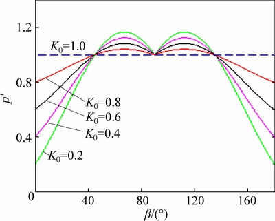
Fig. 4 Relationship between generalized critical internal pressure and direction of fracture under tension-shear mixed cracking
3.2.2 Hydraulic splitting critical water pressure under compression-shear state
According to fracture mechanics theory, when the normal stress fracture ��a is compressive stress, the fracture propagation problem is pure Type II crack problem. Cracks under compressive stress effect turn to be closed, then the normal stress and shear stress pass at the same time during the period of crack closure with uniform contact. In this case, the effective shear stress fractures are:
 (27)
(27)
where �� is the internal friction angle fracture surface and c is the cohesion of the crack surfaces.
According to fracture mechanics theory, the extended Type II fracture criterion is
 (28)
(28)
where  is rock and soil compression-shear complex fracture toughness and KIIcis for Type II fracture toughness values.
Combining Eqs. (19), (20), (22) and (27) into Eq. (28) results in the occurrence of critical pressure head pressure composite shear fracture when the value of hydraulic fracturing is

 (29)
(29)
Incorporating Eqs. (9), (12) and (18) into Eq. (29) results in
 (30)
(30)
where Case 1 denotes no fracture filler; Case 2 denotes fracture containing the filler (the filler does not move); and Case 3 denotes fracture containing the filler (the filler moves with the flow).
The broad definition of composite shear fracture critical pressure water pressure is
 (31)
(31)
For fractures in the filler-containing fluid (the filler does not move), with Eqs. (30)-(31) and Case (2), it can be obtained:
 (32)
(32)
The compression-shear compound fracture relations between generalized critical pressure and crack orientation as well as the lateral pressure coefficients are shown in Fig. 5. Given that  a broad critical pressure curve is generated. Generalized critical minimum pressure at different sides of the pressure coefficient is not the same because the fluid drag force of crack generation caused crack sidewalls. When the lateral pressure coefficient is small, the minimum generalized critical pressure is also small; when the lateral pressure coefficient is close to 1.0, the generalized critical pressure increases to maximum of 1.0.
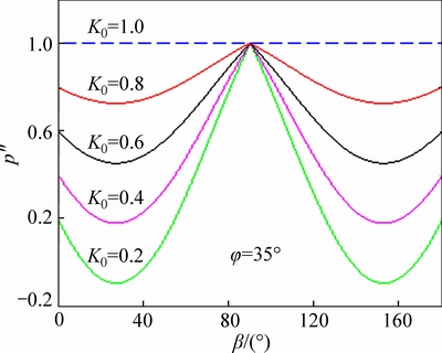
Fig. 5 Relationship between generalized critical pressure and crack orientation under different conditions of pressure shear complex fracture K0
As shown in Fig. 6, the plurality of sets �� value is calculated; it gradually increases as �� and generalized critical water pressure increase. However, the critical pressure generalized fracture direction corresponds to the minimum and maximum principal stress directions to reduce angle ��. And when ��=90��, the distribution feature of generalized critical water pressure of the compression-shear compound fracture is the same with the tensile-shear compound fracture, that is, when ��=0��, the generalized critical pressure has a minimum value.
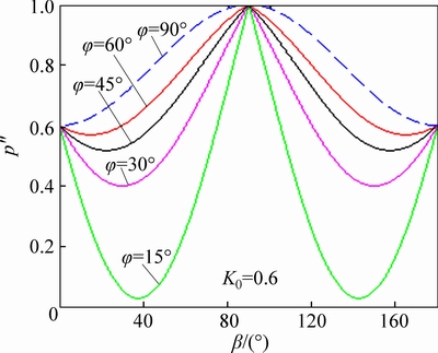
Fig. 6 Relationship between generalized critical pressure and crack orientation under different conditions of pressure shear complex fracture ��
For in situ stress fracture, fracture length, fracture toughness, fracture porosity and hydraulic fracturing in bulk density are constant at the same high head pressure. Under the joint impact move, it is obtained:
 (33)
(33)
Hydrostatic pressure is the most prone to the crack direction of hydraulic fracturing. The analytical solution is shown in Eq. (34).

that is,
 or
or  (34)
(34)
where ��is the angle between crack direction and maximum principal stress and �� is the internal friction angle of fracture surfaces.
4 Case analysis
The high-pressure water inrush in the Wuhan subway tunnel collapsed section is adopted as a case study to illustrate the analysis.
The field data are as follows: stress of crustal stress ��1=520 kPa, ��3=180 kPa, marl rock tensile-shear complex fracture toughness value  280 kN��m-3/2, compression-shear complex fracture toughness
  85 kN��m-3/2, friction angle ��=35�� within the crack surface, crack length 2a=1.7 m, width d=4 mm crack aspect ratio ��=2a/d approaches infinity, and CD=2.05. The filler in the cracks c=14 kPa, filler porosity n=0.25, water density ��=1000 kg/m3between the cracks, fracture flow average velocity =4.85 m/s, and the long axis of the maximum principal stress angle ��=0��.
1) According to Ref. [11], by considering only hydrostatic pressure, the head pressure threshold equation is as follows:
Tension and shear conditions:

 (35)
(35)
Compression-shear situation:
 (36)
(36)
The analysis is performed with Eq. (35). Considering that the occurrence of cracks at position I-II of composite crack propagation, the crack hydraulic fracturing critical water pressure pc=351.35 kPa.
Analysis with Eq. (36) shows that considering the position of Type II cracks, critical hydraulic fracturing head pressure pc=274.28 kPa causes cracks to occur.
2) The hydrostatic and hydrodynamic pressure of the common action case are considered.
The critical water pressure equation under this section in consideration of the hydrostatic and hydrodynamic pressure of the common action resulted in tension and shear conditions of Eq. (24) case 2 and compression-shear conditions of Eq. (30) for case 2.
Analysis is performed with Eq. (24). In consideration of the occurrence of cracks at position I-II composite crack propagation, crack hydraulic fracturing critical water pressure pc=369.46 kPa.
Analysis with Eq. (30) shows that in consideration of the position of Type II cracks in the case, at critical hydraulic fracturing head pressure, pc=248.46 kPa cracks occur.
To sum up, the critical water pressure calculated values are shown in Table 1. By measuring the amount of construction required to monitor water pressure tunnel collapse when the measured value is 253.86 kPa, the theoretical calculations and measured value comparison are shown in Fig. 7.
As shown in Table 1 and Fig. 7, both from Ref. [11] or the result of the calculation equation in this work, the crack head hydraulic fracturing pressure is much larger than the critical field measurement head pressure with regard to cracks I, II composite crack propagation. Therefore, the occurrence of cracks at positions I, II composite crack propagation is unlikely. The site head pressure measured value exceeds that in this work, so we consider hydrodynamic and hydrostatic pressure and the occurrence of Type II crack head pressure of the hydraulic fracturing critical value. However, the value does not reach that in Ref. [11]. Only under water pressure, Type II crack head pressure of the hydraulic fracturing critical value generates. Therefore, critical water pressure values are derived from Eq. (30) to predict more reasonable critical hydraulic fracturing head pressure values.
Table 1 Critical water pressure of hydraulic fracturing (kPa)
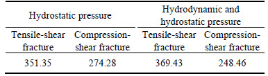
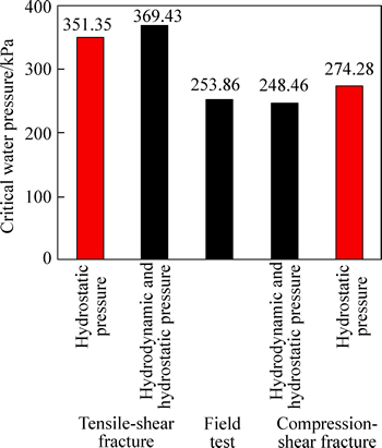
Fig. 7 Comparison of different theoretical calculations and field monitoring values for critical water pressure hydraulic fracturing
In the case of the apparent collapse of the project site, before tunnel collapse, rock joint action hydraulic fracturing, fracture extension, and formation of new cracks that are interconnected occur, causing damage to the tunnel structure and ultimately leading to sudden large-scale tunnel collapse.
The foregoing analysis indicates that under high water pressure, crack propagation is generally a problem. The critical water pressure of hydraulic fracturing calculated in this work after considering hydrodynamic and hydrostatic pressure of the joint action derived from Eq. (30) is much smaller and more consistent with the actual situation than that in Ref. [11]. Therefore, the use of Eq. (30) to predict the critical water pressure of hydraulic fracturing is more reasonable.
5 Conclusions
1) Three cases of fissure fluid, namely, fracture fluid is water, water containing crack filler and the filler does not move, and fracture filling containing water and the filling moves, are summarized. The hydrodynamic pressure on the fractured rock wall for the three cases is deduced to cut the drag force equation.
2) In consideration of hydrodynamic and hydrostatic pressure, it is found that critical water pressure hydraulic fracturing occurs when the three conditions of fissure fluid and water movement under pressure are most prone to hydraulic fracturing crack angle.
3) In the mechanical transformation of the surrounding rock groundwater mainly through the gap hydrostatic and hydrodynamic pressure effect, hydrostatic and hydrodynamic pressure are applied to create the wall rock hydraulic fracturing effect. Hence, the rock fissure enhances connectivity and crack expansion deformation, resulting in fissure permeability enhancement, reduced rock strength, and accelerated destruction of the surrounding rock. The hydraulic fracturing effect may cause serious landslides and other engineering disasters.
4) Under high water pressure, crack propagation generally belongs to Type II crack; by considering the hydrodynamic and hydrostatic pressure of the joint action, the occurrence of Type II crack of hydraulic fracturing critical water pressure is smaller and more consistent with the actual situation than when only the equation of hydrostatic pressure is considered. Hence, the prediction of hydraulic fracturing critical water pressure values is more reasonable.
References
[1] JULIAN B R, FOULGER G R, MONASTERO F C, BJORNSTAD S. Imaging hydraulic fractures in a geothermal reservoir [J]. Geophysical Research Letters, 2010, 37(7): 1-5.
[2] YANG Xiao-li, QIN Chang-bing. Limit analysis of supporting pressure in tunnels with regard to surface settlement [J]. Journal of Central South University, 2015, 22(1): 303-309.
[3] YANG Xiao-li, LONG Ze-xiang. Roof collapse of shallow tunnels with limit analysis method [J]. Journal of Central South University, 2015, 22(5): 1929-1936.
[4] CHEN Wei-tao, WANG Ming-nian, WEI Long-hai, JI Yan-lei, GAI Zhi-ying, HUANG Ren-de. Analysis of causes and disposals for water gushing of land regions Xiamen of submarine tunnel [J]. Chinese Journal of Geotechnical Engineering, 2008, 30(3): 457-461. (in Chinese)
[5] TANG Xiong-jun, FAN Jian-hai, ZHANG Tao, WANG Yuan-han. Analysis and treatment of the collapse in Erdaoya tunnel [J]. Modern Tunneling Technology, 2007, 44(4): 73-78. (in Chinese)
[6] HUBBERT M K, WILLIS D G. Mechanics of hydraulic fracturing [J]. AIME Petroleum Transactions, 1957, 210: 153-168.
[7] NOBARI E S, LEE K L, DUNCAN J M. Hydraulic fracturing in zoned earth and rockfill darns [R]. Berkley, California: University of California, l999.
[8] DING Jin-li, SUN Ya-ping. Analysis of stress of thick wail cylinder of compacted soil in hydraulic fracturing experiment [J]. Journal of Hydraulic Engineering, 1987(3): 16-22. (in Chinese)
[9] YANG You-kui, XIAO Chang-fu, QIU Xian-de, WU Gang. Fracture geometry and pressure distribution in fracture for hydro-fracturing [J]. Journal of Chongqing University: Natural Science, 1995, 19(3): 20-26. (in Chinese)
[10] ZHAN Mei-li, CEN Jian. Experimental and analytical study of hydraulic fracturing of cylinder sample [J]. Chinese Journal of Rock Mechanics and Engineering, 2007, 26(61): 1173-1181. (in Chinese)
[11] HUANG Run-qiu, WANG Xian-neng, CHEN Long-sheng. Study on the effect of hydraulic fracturing during water gushing in deep tunnel [J]. Chinese Journal of Rock Mechanics and Engineering, 2000, 19(5): 573-576. (in Chinese)
[12] LI Zong-li, REN Qing-wen. Analysis and discussion on rock and concrete material hydraulic fracturing under natural power [J]. Rock and Soil Mechanics, 2008, 29(8): 2121-2125. (in Chinese)
[13] SHENG Jin-chang, ZHAO Jian, SU Bao-yu. Analysis of hydraulic fracturing in hydraulic tunnels [J]. Chinese Journal of Rock Mechanics and Engineering, 2005, 24(7): 1226-1230. (in Chinese)
[14] FRALDI M, GUARRACINO F. Limit analysis of collapse mechanisms in cavities and tunnels according to the Hoek-Brown failure criterion [J]. International Journal of Rock Mechanics and Mining Sciences, 2009, 46(4): 665-673.
[15] FRALDI M, GUARRACINO F. Evaluation of impending collapse in circular tunnels by analytical and numerical approaches [J]. Tunneling and Underground Space Technology, 2011, 26(4): 507-516.
[16] FRALDI M, GUARRACINO F. Analytical solutions for collapse mechanisms in tunnels with arbitrary cross sections [J]. International Journal of Solids and Structures, 2010, 47(2): 216-223.
[17] YANG X L, HUANG F. Collapse mechanism of shallow tunnel based on nonlinear Hoek-Brown failure criterion [J]. Tunneling and Underground Space Technology, 2011, 26(6): 686-691.
[18] YANG X L, YAN R M. Collapse mechanism for deep tunnel subjected to seepage force in layered soils [J]. Geomechanics and Engineering, 2015, 8(5): 741-756.
[19] YANG X L. Upper bound limit analysis of active earth pressure with different fracture surface and nonlinear yield criterion [J]. Theoretical and Applied Fracture Mechanics, 2007, 47(1): 46-56.
[20] YANG X L, QIN C B. Limit analysis of rectangular cavity subjected to seepage forces based on Hoek-Brown failure criterion [J]. Geomechanics and Engineering, 2014, 6(5): 503-515.
[21] KAWAMOTO T, ICHIKAWA Y, KYOYA T. Deformation and fracturing behaviour of discontinuous rock mass and damage mechanics theory [J]. International Journal for Numerical & Analytical Methods in Geomechanics, 1988, 12(4): 321-327.
[22] EVEET J B, LIU C. Fundamentals of fluid mechanics [M]. New York: McGraw-Hill, 1997: 381-390.
(Edited by FANG Jing-hua)
Foundation item: Project(50908234) supported by the National Natural Science Foundation of China; Project(2011CB710604) supported by the Basic Research Program of China
Received date: 2015-07-02; Accepted date: 2015-11-02
Corresponding author: ZHOU Zhong, Associate Professor, PhD; Tel: +86-13319541496; E-mail: 369144091@qq.com
Abstract: According to the stress state of the crack surface, crack rock mass can be divided into complex composite tensile-shear fracture and composite compression-shear fracture from the perspective of fracture mechanics. By studying the hydraulic fracturing effect of groundwater on rock fracture, the tangential friction force equation of hydrodynamic pressure to rock fracture is deduced. The hydraulic fracturing of hydrostatic and hydrodynamic pressure to rock fracture is investigated to derive the equation of critical pressure when the hydraulic fracturing effect occurs in the rock fracture. Then, the crack angle that is most prone to hydraulic fracturing is determined. The relationships between crack direction and both lateral pressure coefficient and friction angle of the fracture surface are analyzed. Results show that considering the joint effect of hydrodynamic and hydrostatic pressure, the critical pressure does not vary with the direction of the crack when the surrounding rock stationary lateral pressure coefficient is equal to 1.0. Under composite tensile-shear fracture, the crack parallel to the direction of the main stress is the most prone to hydraulic fracturing. Under compression-shear fracture, the hydrodynamic pressure resulting in the most dangerous crack angle varies at different lateral pressure coefficients; this pressure decreases when the friction angle of the fracture surface increases. By referring to the subway tunnel collapse case, the impact of fractured rock mass hydraulic fracturing generated by hydrostatic and hydrodynamic pressure joint action is calculated and analyzed.
