
DOI: 10.11817/j.ysxb.1004.0609.2021-39646
�缫��״�����ֲ��Ⱥ����Ͻ����㺸��ͷ��ò��Ӱ��
ë��1���� ӯ2��������1���»���2����˧��1
(1. �ൺ�ķ����������ɷ�����˾���ൺ 266111��
2. �й���ѧԺ�����о��� �й���ѧԺ���ò����밲ȫ�����ص�ʵ���ң����� 110016)
ժ Ҫ��
Ϊ��ȷԤ�����ֲ��Ⱥ����Ͻ����㺸�ۺ˳ߴ缰������ò�������ۺϿ��ǵ���㺸�����е缫�빤���������빤����Ӵ�����Ķ�̬�仯�Լ�������ѧ���ܶԽӴ������Ӱ�죬�����˽�Ϊ���Ƶĵ���㺸����Ԫģ�ͣ��о����ֲ��Ⱥ����Ͻ����㺸�ۺ��γɻ����Լ��缫Բ�ǰ뾶�Խ�ͷ��ò��Ӱ����ɡ�����������ۺ������ں����Ե�γɣ�Ȼ����������չ�����ź���ʱ����ӳ����ۺ˽�������Բ������ת�䣻�缫Բ�ǰ뾶���㺸�ۺ˳ߴ硢ѹ����Ⱥ���߶����ӡ�ģ�ͼ���õ����ۺ˳ߴ�ͺ��������ò��ʵ�������ϽϺã���֤��ģ�͵���Ч�ԡ�
�ؼ��ʣ�
���Ͻ�������㺸����ֵģ�����ۺ���״��������ò��
���±�ţ�1004-0609(2021)-02-0333-09���� ��ͼ����ţ�TG146.1���� ���ױ�־�룺A
���ĸ�ʽ��ë��, �� ӯ, ������, ��. �缫��״�����ֲ��Ⱥ����Ͻ����㺸��ͷ��ò��Ӱ��[J]. �й���ɫ����ѧ��, 2021, 31(2): 333-341. DOI: 10.11817/j.ysxb.1004.0609.2021-37713
MAO Zhen-dong, KAN Ying, HAN Xiao-hui, et al. Influence of electrode shape on resistance spot welding joint morphology of dissimilar unequal thickness aluminum alloys[J]. The Chinese Journal of Nonferrous Metals, 2021, 31(2): 333-341. DOI: 10.11817/j.ysxb.1004.0609.2021-37713
���Ͻ�������ܶ�С����ǿ�ȸߵ��ŵ�����㷢Ӧ���ں��պ��졢�������졢�����ͨ������[1]���缫��״��Ӱ�����Ͻ����㺸�ۺ������Ĺؼ�����֮һ[2]��Ŀǰ����������������ڵ缫��״�Ժ�������Ӱ����о�[3-5]��ZHANG��[6]�о��˵缫ĥ���DP600�ֵ㺸�ۺ˳ߴ��Ӱ�죬������������缫��ĥ���ۺ˳ߴ��С��TUCHTFELD��[7]�о����֣����缫����ֱ����ͬʱ���缫�������ۺ˳ߴ��С��Ȼ����Щ�о���༯��������缫���ε缫�У���ƽ��缫�о����١�ƽ��缫���ŵ����ڱ�֤�ۺ˳ߴ��ͬʱ���Ի�ý�dz��ѹ����ȣ����������Ͻ��Ⱥ͵��������ã�ͨ��ʹ�ô��������ʱ�䡢��ѹ���ġ�Ӳ�淶�����е���㺸�������˵缫��ĥ���ճ�������µ㺸�缫����Բ�ǰ뾶������Ӱ���ۺ˴�С�ͺ������������
�ڸ����������Ͻ�㺸��ʵ��Ӧ���У����ǵ��ṹǿ�Ⱥ������������أ���Ҫ�����ֲ��Ⱥ����Ͻ���е���㺸���ӡ�Ŀǰ�������ֲ��Ⱥ����Ͻ����㺸���յ��о���Ҫ����ʵ��ķ�����Ȼ�����Ͻ�ĺ�ȡ�������ȴ���״̬�ȶ���Ե㺸�ۺ���������Ӱ�졣ÿһ�ֺ�Ⱥ�������ϵ����Ͻ����㺸���ն���Ҫ����ʵ�飬�����Ż����ڳ������⣬���Ͻ����㺸��˲ʱ�Ը��㺸�ۺ��γɻ������о������ܴ����ѡ���ֵģ������ֲ�ʵ���о��IJ��㣬����������ѧ��������ֵģ�⼼���Ե���㺸���̽������о�[8-11]����Ŀǰ���в�������Ԫ���о��缫��״�����ֲ��Ⱥ����Ͻ�㺸����Ӱ��ı�����
�����ۺϿ��ǵ���㺸�����е缫�빤���������빤����Ӵ�����Ķ�̬�仯�Լ�������ѧ���ܶԽӴ������Ӱ�죬�����˽�Ϊȷ�����ֲ��Ⱥ����Ͻ����㺸����Ԫģ�͡�ͨ����ֵģ���о����ֲ��Ⱥ����Ͻ�㺸�ۺ��γɻ�����ƽ��缫����Բ�ǰ뾶���ۺ˳ߴ缰������ò��Ӱ����ɣ�Ϊ�������ֲ��Ⱥ����Ͻ����㺸�����ṩ�������ݡ�
1 ����Ԫģ��
���Ľ����ĵ���㺸����Ԫģ����ͼ1��ʾ��Ϊ��ά��Գ�ģ�͡��ϡ��µ缫�ߴ���ͬ��ֱ��Ϊ19 mm���缫����ĵ�Բ�ǰ뾶RΪ1~4 mm����������Ϊ6 mm��5083��4 mm��7N01���Ͻ��ġ�ģ���д��������İ뾶Ϊ25 mm��ͨ���ڵ缫-����������-�������������ýӴ��Եķ���ģ�����ĽӴ���Ϊ��
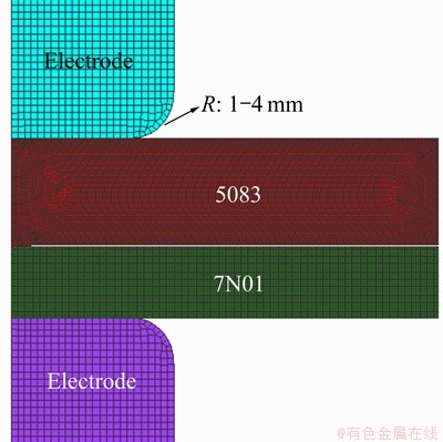
ͼ1 ����㺸����Ԫģ��
Fig. 1 Resistance spot welding simulation model
����Bay-Wanheim[12]ģ�ͼ�������ĽӴ������� ����ģ����ʽ���£�
 (1)
(1)
ʽ�У� �Ӵ������Ͻ������ϵ�����Ӧ����
 �ǽ��淨���ϵ�ѹ����
 ��
�� �ֱ��ǽӴ����������ϵĵ����ʣ�
 �ǽ���Ϳ�㡢��Ⱦ��ȵĵ����ʡ�����Bay-Wanheimģ�Ϳ��ۺϿ��Dz�������Ӧ�����Ӵ�ѹ���ͽ�����Ⱦ��ԽӴ������Ӱ�죬Ϊȷ�����������Ͻ�ĽӴ������ṩ������
����ߴ��ģ��������ҪӰ�죬�ۺϿ���ģ��ȷ�Ժͼ���Ч�ʣ������°�Ӵ�����������оֲ�ϸ������С����߳�Ϊ0.05 mm�����ಿ�ֵ�����߳�Ϊ0.3 mm��ģ���в��õĹ��ղ���Ϊ�����ӵ���47 kA��ʱ��25 ms���缫ѹ��18 kN����ʵ�ʺ��ӹ��ղ���һ�¡�
������ʹ�õĵ缫�ʹ���ĸ�ĵ������Ժ���ѧ���ܲ�����ͼ2[7, 13]��7N01��5083���Ͻ������Ӧ��Ӧ��������ͼ3��ʾ��������7N01��5083���Ͻ�ĵ�����Ӧ�� ��
�� �ֱ���ʽ(2)��ʽ(3)����[14-15]��

 (2)
(2)

 (3)
(3)
����
 (4)
(4)
ʽ�У� ΪӦ�����ʣ�TΪ�¶ȣ�RΪĦ�����峣����QΪ���μ����ܣ�7N01��5083���Ͻ��Q�ֱ�Ϊ152��164 kJ/mol��
2 ģ���������
2.1 ���ֲ��Ⱥ����Ͻ����㺸�ۺ��γɻ���
ͼ4��ʾΪ�缫Բ�ǰ뾶2 mmʱ��ͬ����ʱ���º����¶ȷֲ���ͼ����ͼ4���Կ������㺸�ۺ������ڹ���-�����Ӵ�����ı�Ե�γɣ�Ȼ���ؽ�����������չ����һ���ӳ�ͨ��ʱ����ۺ˽����ɽ�����Բ������ת�䣬��ͼ4(d)��ʾ�����յõ����ۺ���ʵ��õ����ۺ���̬���ߴ�һ��(��ͼ4(e))��֤��������Ԫģ�͵���Ч�ԡ�
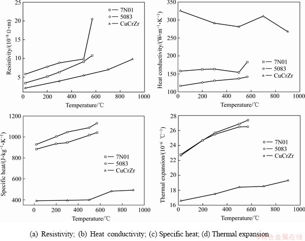
ͼ2 �缫�ʹ���ĸ�ĵ��������ܺ���ѧ���ܲ���
Fig. 2 Thermo-physical and mechanical properties of electrode and base metals
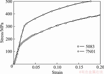
ͼ3 7N01��5083���Ͻ�����Ӧ��-Ӧ������
Fig. 3 Stress-strain curves of 5083 and 7N01 at 20 ��
ͼ5��ʾΪ��ͬ����ʱ���¹���-���������ϵ�ѹ���ֲ����ߡ����Կ������ڵ㺸�����У��������ĵĽӴ�ѹ��ʼ�մ��ڽ����Ե�ĽӴ�ѹ�������ݹ�ʽ(1)��֪���Ӵ���������Ӵ�ѹ���ɷ��ȣ���˵㺸�ۺ������ڽӴ�ѹ����С�ĽӴ���Ե�γɡ�ͼ6��ʾΪ�㺸�����е缫-����������-������Ӵ��뾶��ʱ��仯���ߡ����Կ��������ӹ����й���-������ĽӴ��뾶���������ƣ��缫-������ĽӴ��뾶�ȼ�С�������������ڵ缫�·����ϼ��Ⱥ�������ͣ�ʹ�����������������������������缫�Ӵ��뾶��С�����ź���ʱ�������������¶����ߣ�����Ӧ���½����ڵ缫ѹ�������£������������Σ���˵缫�빤���Ӵ��뾶����һ���۲�ͼ6��ͼ4(c)���Է��֣��缫-�����Ӵ��뾶�����յ�ʱ����Ӧ���ۺ���̬�ɽ�����Բ������ת��Ŀ�ʼ�����ŵ缫-�����Ӵ��뾶�ɼ�СתΪ�����ۺ��ϲ����²���ƽ���ڰ�ĵķ�����չ���γɽ������Ϊ���ε��ۺˡ�
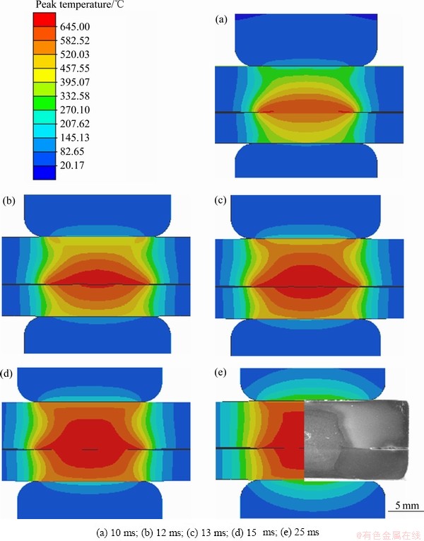
ͼ4 �缫Բ�ǰ뾶Ϊ2 mmʱ��ͬ����ʱ���µ��¶ȳ�
Fig. 4 Temperature distribution at different time with electrode fillet radius of 2 mm
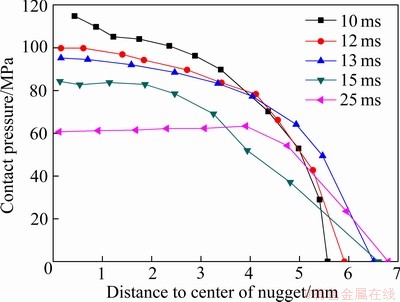
ͼ5 ��ͬ����ʱ���¹���-��������Ӵ�ѹ��
Fig. 5 Contact pressure between workpieces with time
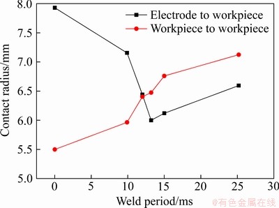
ͼ6 ����Ӵ��뾶��ʱ��仯����
Fig. 6 Change of contact radius of interfaces with time
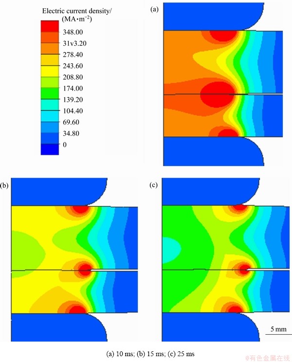
ͼ7 ��ͬʱ���¹����е����ܶ�
Fig. 7 Change of current density in workpiece with time
���½�ϵ㺸�����е����ܶȷֲ������缫-�����Ӵ��뾶���ۺ���״Ӱ��Ļ���(��ͼ7)����ͼ7��ʾ�����ź���ʱ����������������������ܶȳ��½����ƣ������ܶ����һֱλ�ڵ缫-���������Ե����-���������Ե��һ���棬�㺸�����У�����-��������Ӵ�����͵����ܶ����ͣ��������IJ��ȼ��٣��ۿ���չ��������һ���棬�缫-�����Ӵ��뾶�������º������±����������ܶ����Ե�ƶ����ٽ��ۺ�����Բ���ν���ת�䡣
2.2 �缫Բ�ǰ뾶���ۺ˳ߴ缰������ò��Ӱ��
ͼ8��ʾΪ�㺸��ͷ��״��������ʾ��ͼ�������ϰ��ۿ����°��ۿ�������Ϊ�ۺ˳ߴ��������߶Ⱥ�ѹ�����Ϊ��ͷ������ò�������ڵ㺸�����У�ƽ��缫�ᷢ��ĥ�𣬵��¶���Բ�����ο�ʵ�ʵ缫��ĥ�����������ģ���˶���Բ�ǰ뾶RΪ1~4 mmʱ�㺸��ͷ��״�����仯�������ͼ9��10��ʾ�����Կ��������ŵ缫Բ�ǰ뾶�����ۺ˳ߴ硢ѹ����Ⱥ���߶�����ѹͷԲ�ǰ뾶Ϊ4 mmʱ���㺸��ͷ������߶��������ӡ�
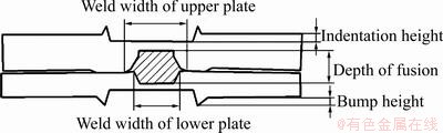
ͼ8 �㺸��ͷ��״����ʾ��ͼ
Fig. 8 Schematic diagram of shape parameters of joint
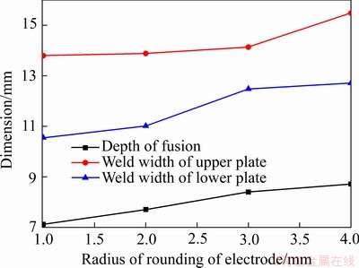
ͼ9 ��ͬ�缫Բ�ǰ뾶ʱ���ۺ˳ߴ�
Fig. 9 Size of nugget under different corner radiuses
ͼ11��ʾΪʹ��R4�缫�㺸�����е�Ч����Ӧ��ֲ���ͼ����˿�����������㺸��ͷ������߶��������ӵ�ԭ����ͼ11���Կ������㺸�����б������ȳ����ڹ���-�������洦�����Ч����Ӧ������ֵλ�ڽ����Ե�����ŵ㺸���У���ͨ��7 msʱ��缫Բ�Ǵ��Ӵ��Ĺ�����ʼ�������Ա��Σ��ӳ�ͨ��ʱ�䣬����������ϵ����Ա��ν�һ�������ڵ缫��Χ�ѻ��γ���
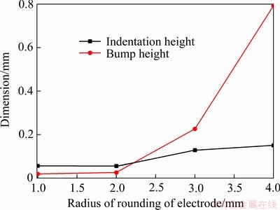
ͼ10 ��ͬ�缫Բ�ǰ뾶ʱ��ѹ����Ⱥ���߶�
Fig. 10 Indentation depth and pile-up height under different corner radiuses
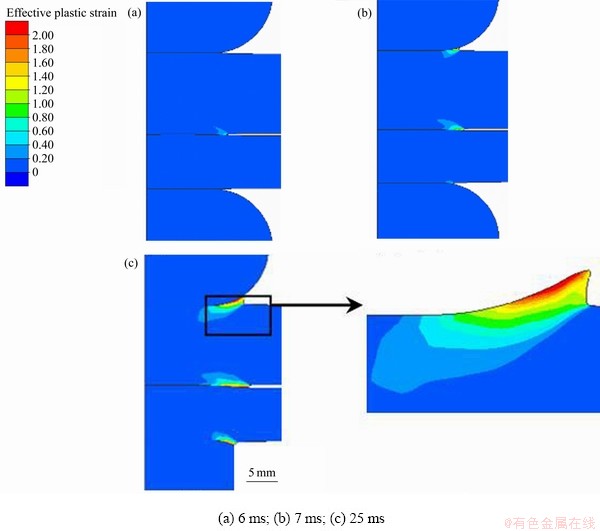
ͼ11 �뾶4 mmԲ�ǵ缫�㺸������ĸ�ĵ�ЧӦ��ֲ���ͼ
Fig. 11 Effective plastic strain distribution along time for base metal during resistance spot welding using R4 mm electrode
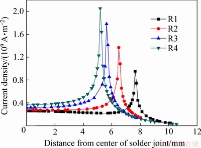
ͼ12 7 msʱ��ͬԲ�ǰ뾶�¹�����������ܶ�
Fig. 12 Current density on surface under different corner radiuses at 7 ms
ͼ12��13��ʾ�ֱ�Ϊͨ��7 msʱ������������ܶȷֲ����¶ȷֲ�ͼ����ͼ12���Կ��������ŵ缫Բ�ǰ뾶����������ĵ����ܶ����ֵ���ߣ���˽ϴ�Բ�ǰ뾶�ĵ缫��Ӧ�Ĺ��������¶Ƚϸߣ���ͼ13��ʾ���缫�뾶Ϊ4mmʱ�������γ��˳ʻ�״�ֲ���600����´������¶������Ͻ������Ӧ���ܵ�[13]���ڵ缫ѹ�������¸û�״�����������Ա��Σ��Ӷ��ڲ��ϱ����γɶѻ���ͼ14�Dz���R2��R4�缫�㺸��ı�����ò�����Ƭ�����Կ���R2�缫����������𣬶�R4�缫������������ԣ�����ͼ4(e)��ͼ11(c)��ʾ��ģ��������һ�£�ͼ14(b)�е���߶Ȳ����ȣ�����Ҫ������ʵ�ʵ㺸�����е缫������λ�ò�����ȫ�Գƣ��������²��ϱ��ο�����С������ڲ����ȵ�����״̬�²���������һ��ѻ���
3 ����
1) ���������ֲ��Ⱥ����Ͻ����㺸�ĵ�- ��-����ϵ�����Ԫģ�ͣ�ʵ�������ֲ��Ⱥ����Ͻ����㺸�ۺ˳ߴ�ͱ�����ò��ȷԤ�⡣
2) ���ֲ��Ⱥ����Ͻ�㺸�ۺ��γɹ���Ϊ���ۺ������ڹ���-�����Ӵ���Ե�γɣ�Ȼ����������չ�����ź���ʱ�����ӣ��ۺ˽�������Բ������ת�䡣
3) �㺸�ۺ˳ߴ硢ѹ����Ⱥ���߶���缫Բ�ǰ뾶���������
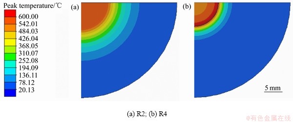
ͼ13 7 msʱ��ͬԲ�ǰ뾶�¹��������¶�
Fig. 13 Temperature distribution on surface under different corner radiuses at 7 ms
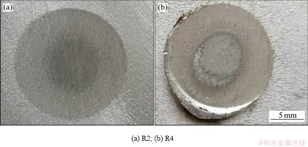
ͼ14 ��ͬ�缫Բ�ǰ뾶ʱ���������ò
Fig. 14 Surface morphologies under different corner radiuses at 7 ms
REFERENCES
[1] ������, ������. �������Ͻ���Ͻ�չ[J]. �й���ɫ����ѧ��, 2019, 29(9): 2115-2141.
DENG Yun-lai, ZHANG Xin-ming. Development of aluminium and aluminium alloy[J]. The Chinese Journal of Nonferrous Metals, 2019, 29(9): 2115-2141.
[2] WEI P S, WU T H. Numerical study of electrode geometry effects on resistance spot welding[J]. Science and Technology of Welding and Joining, 2013, 18(8): 661-670.
[3] �� ��, �� ��, �� ��. �缫��״��AA5182���Ͻ����㺸���ܵ�Ӱ��[J]. ����ѧ��, 2018, 39(4): 84-88.
ZHANG Min, KONG Liang, WANG Min. Study of electrode tip morphology on the performance in resistance spot welding of AA5182 aluminum alloy[J]. Transactions of the China Welding Institution, 2018, 39(4): 84-88.
[4] WANG B, HUA L, WANG X, et al. Effects of electrode tip morphology on resistance spot welding quality of DP590 dual-phase steel[J]. The International Journal of Advanced Manufacturing Technology, 2016, 83(9): 1917-1926.
[5] ���ǧ, ����Ө, �� ��, ��. �缫��״����-�ֵ㺸��ͷ��֯����ѧ���ܵ�Ӱ��[J]. ��е����ѧ��, 2016, 52(24): 36-43.
SUN Da-qian, ZHANG Min, SU Lei, et al. Effects of electrode morphology on microstructures and mechanical properties of spot welded Al-steel joints[J]. Journal of Mechanical Engineering, 2016, 52(24): 36-43.
[6] ZHANG X Q, CHEN G L, ZHANG Y S. Characteristics of electrode wear in resistance spot welding dual-phase steels[J]. Materials & Design, 2008, 29(1): 279-283.
[7] TUCHTFELD M, HEILMANN S, F��SSEL U, et al. Comparing the effect of electrode geometry on resistance spot welding of aluminum alloys between experimental results and numerical simulation[J]. Welding in the World, 2019, 63(2): 527-540.
[8] HAMEDI M, ATASHPARVA M. A review of electrical contact resistance modeling in resistance spot welding[J]. Welding in the World, 2017, 61(2): 269-290.
[9] MANLADAN S M, YUSOF F, RAMESH S, et al. A review on resistance spot welding of aluminum alloys[J]. The International Journal of Advanced Manufacturing Technology, 2017, 90(1): 605-634.
[10] WAN Z, WANG H, WANG M, et al. Numerical simulation of resistance spot welding of Al to zinc-coated steel with improved representation of contact interactions[J]. International Journal of Heat and Mass Transfer, 2016, 101: 749-763.
[11] �� ��, �� ��, �� ��, ��. ���ֲ��Ⱥ����Ͻ����㺸��������ֵģ��[J]. ����ѧ��, 2017, 38(10): 61-65.
ZHANG Yu, BI Jing, LUO Zhen, et al. numerical simulation of shunting in resistance spot welding for dissimilar unequal-thickness aluminum alloys[J]. Transactions of the China Welding Institution, 2017, 38(10): 61-65.
[12] BAY N, WANHEIM T. Real area of contact and friction stress at high pressure sliding contact[J]. Wear, 1976, 38(2): 201-209.
[13] WANG J, WANG H, LU F, et al. Analysis of Al-steel resistance spot welding process by developing a fully coupled multi-physics simulation model[J]. International Journal of Heat and Mass Transfer, 2015, 89: 1061-1072.
[14] ������, ������, ����, ��. 7N01���Ͻ���ѹ��������Ϊ�о�[J]. ϡ�н���, 2011, 35(6): 812-817.
LIU Jun-cheng, JIN Long-bing, HE zhen-bo, et al. Hot deformation behavior of 7N01 aluminum alloy[J]. Chinese Journal of Rare Metals, 2011, 35(06): 812-817.
[15] ������, �����. 5083���Ͻ���ѹ��Ӧ��-Ӧ�������������ȼӹ�ͼ[J]. �й���ɫ����ѧ��, 2018, 28(9): 1737-1745.
GAO Wen-li, GUAN Yu-fei. Correction of flow stress-strain curve and processing maps of 5083 aluminum alloy during hot compression[J]. The Chinese Journal of Nonferrous Metals, 2018, 28(9): 1737-1745.
Influence of electrode shape on resistance spot welding joint morphology of dissimilar unequal thickness aluminum alloys
MAO Zhen-dong1, KAN Ying2, HAN Xiao-hui1, CHEN Huai-ning2, LI Shuai-zhen1
(1. CRRC Qingdao Sifang Co., Ltd., Qingdao 266111, China;
2. CAS Key Laboratory of Nuclear Materials and Safety Assessment, Institute of Metal Research, Chinese Academy of Sciences, Shenyang 110016, China)
Abstract: In order to accurately predict the nugget size and surface morphology of the resistance spot welded dissimilar unequal thickness aluminum alloy joint, a finite element model was established. The dynamic contact between the electrode and the workpieces and the influence of mechanical behavior of the workpieces on the contact resistivity were considered in the model. The nugget formation mechanism of the aluminum alloy during resistance spot welding and the influence of corner radius of the electrode on the joint were analyzed. The calculated results show that the initial nugget forms at the edge of the weld point, then propagates to the center. With the welding time increasing, the cross section of the nugget changes from generally elliptical to square. Besides, the nugget size, the indentation depth and pile-up height increase with the corner radius of the electrode increasing. The effectiveness of the numerical model was verified by comparing the calculated result with experimental result.
Key words: aluminum alloy; resistance spot welding; numerical simulation; nugget shape; surface morphology
Received date: 2020-01-10; Accepted date: 2020-05-20
Corresponding author: KAN Ying; Tel: +86-24-23971932��E-mail: ykan@imr.ac.cn
(�༭ ������)
�ո����ڣ�2020-01-10�������ڣ�2020-05-20
ͨ�����ߣ��� ӯ�����о�Ա����ʿ���绰��024-23971932��E-mail��ykan@imr.ac.cn
ժ Ҫ��Ϊ��ȷԤ�����ֲ��Ⱥ����Ͻ����㺸�ۺ˳ߴ缰������ò�������ۺϿ��ǵ���㺸�����е缫�빤���������빤����Ӵ�����Ķ�̬�仯�Լ�������ѧ���ܶԽӴ������Ӱ�죬�����˽�Ϊ���Ƶĵ���㺸����Ԫģ�ͣ��о����ֲ��Ⱥ����Ͻ����㺸�ۺ��γɻ����Լ��缫Բ�ǰ뾶�Խ�ͷ��ò��Ӱ����ɡ�����������ۺ������ں����Ե�γɣ�Ȼ����������չ�����ź���ʱ����ӳ����ۺ˽�������Բ������ת�䣻�缫Բ�ǰ뾶���㺸�ۺ˳ߴ硢ѹ����Ⱥ���߶����ӡ�ģ�ͼ���õ����ۺ˳ߴ�ͺ��������ò��ʵ�������ϽϺã���֤��ģ�͵���Ч�ԡ�
[1] ������, ������. �������Ͻ���Ͻ�չ[J]. �й���ɫ����ѧ��, 2019, 29(9): 2115-2141.
[3] �� ��, �� ��, �� ��. �缫��״��AA5182���Ͻ����㺸���ܵ�Ӱ��[J]. ����ѧ��, 2018, 39(4): 84-88.
[5] ���ǧ, ����Ө, �� ��, ��. �缫��״����-�ֵ㺸��ͷ��֯����ѧ���ܵ�Ӱ��[J]. ��е����ѧ��, 2016, 52(24): 36-43.
[11] �� ��, �� ��, �� ��, ��. ���ֲ��Ⱥ����Ͻ����㺸��������ֵģ��[J]. ����ѧ��, 2017, 38(10): 61-65.
[14] ������, ������, ����, ��. 7N01���Ͻ���ѹ��������Ϊ�о�[J]. ϡ�н���, 2011, 35(6): 812-817.
[15] ������, �����. 5083���Ͻ���ѹ��Ӧ��-Ӧ�������������ȼӹ�ͼ[J]. �й���ɫ����ѧ��, 2018, 28(9): 1737-1745.
