
J. Cent. South Univ. Technol. (2011) 18: 940-945
DOI: 10.1007/s11771-011-0784-5![]()
Analytic model of non-uniform corrosion induced cracking of reinforced concrete structure
ZHANG Xiao-gang(��С��)1, WANG Xue-zhi(��ѧ־)2, LU Zhao-hui(¬����)3, XING Feng(�Ϸ�)1
1. Shenzhen Municipal Key Laboratory for Durability of Civil Engineering Structure,
College of Civil Engineering, Shenzhen University, Shenzhen 518060, China;
2. College of Civil Engineering, Liaoning University of Technology, Jinzhou 121001, China;
3. School of Civil Engineering and Architecture, Central South University, Changsha 410075, China
? Central South University Press and Springer-Verlag Berlin Heidelberg 2011
Abstract:
In order to perfectly reflect the dynamic corrosion of reinforced concrete (RC) cover in practical engineering, an analytic model of non-uniform corrosion induced cracking was presented based on the elastic-plastic fracture mechanics theory. Comparisons with the published experimental data show that the predictions given by the present model are in good agreement with the results both for natural exposed experiments and short-time indoor tests (the best difference is about 2.7%). Also it obviously provides much better precision than those models under the assumption of uniform corrosion (the maximal improved precision is about 48%). Therefore, it is pointed out that the so-called uniform corrosion models to describe the cover cracking of RC should be adopted cautiously. Finally, the influences of thickness of local rusty layer around the reinforcing steel bar on the critical corrosion-induced crack indexes were investigated. It is found that the thickness of local rusty layer has great effect on the critical mass loss of reinforcing steel, threshold expansion pressure, and time to cover cracking. For local rusty layer thickness with a size of a��0.5 mm, the time to cover cracking will increase by about one times when a/b (a, semi-minor axis; b, semi-major axis) changes from 0.1 to 1 mm.
Key words:
1 Introduction
Corrosion of reinforcement bars in RC structure due to chloride or CO2 contamination is one of the primary causes that lead to the loss of its durability. And the time to corrosion induced cracking of concrete cover is of great importance for the service life predictions of RC structure in corrosive environments. Therefore, considerable corrosion models of reinforcement bars [1-7] were suggested in the past decades. However, in those models, it was assumed that the expansive corrosion products were uniform around the bar, which was so-called uniform corrosion assumption. Although the research background and corresponding useful findings were presented in the above models, due to the complexity of the problem, those simplified methods are not in agreement with the non-uniform distribution of corrosion products around the steel bar in practical engineering. According to the detailed inspections of corrosion product shape around the bar in practical engineering, it is pointed out that the corrosion of bar will happen at first near the side of the concrete cover, then the corrosion range will extend to the whole surface of the bar [8]. This is because the corrosive ions such as chloride ion, CO2 will gather more in the closer side near the external corrosion environment, thus inducing the corrosion in the relative area. The stress state and the initial defects are variant in different local areas even in the same member of the same structure, thus inducing unequal amount of corrosive ions, O2 outside in these local places. As a result, the radial and longitudinal non-uniform corrosion of reinforcement bar will happen. However, a review of the corresponding published literatures reveals that the analytic model of non-uniform corrosion induced cracking of reinforced concrete (RC) cover has not been proposed up till now.
At present, the cracking of cover is generally defined by the appearance of the first visible cracks on the surface of concrete. Actually, the corrosion-induced cover cracking is a dynamic process that is composed of crack initiation, propagation and cover spalling stages. The fine cracks in the concrete cover induced by the non-uniform corrosion will undergo the initiation and propagation processes before the first visible crack on the surface of concrete is observed. For accelerated experiments in the laboratory, it can be considered that the time to cover cracking and the time to crack initiation are the same, but in practical engineering, due to the natural lasting corrosion, there is a step-by-step propagation process for the corrosion-induced cover cracking. The time at which the surface crack is observed cannot represent the time of crack initiation. The propagation of fine cracks induced by the non-uniform corrosion has a long-term influence on the corrosion cracking process. This process is realized by the gradual increase of the corrosion products. As a result, the dynamic corrosion-induced cover cracking process should be paid more attention to.
The object of the present work is to investigate the dynamic non-uniform corrosion of reinforced concrete (RC) cover, and an analytic model for it is proposed. Finally, the influences of thickness of local rusty layer around the reinforcing steel bar on the critical mass loss of reinforcing steel, threshold expansion pressure and time to cover cracking are investigated.
2 Model of non-uniform corrosion induced cracking and its verification
It was pointed out that the diametrical non-uniform corrosion shape could be considered as elliptical shape based on the detailed circumferential thickness measure on the expansive corrosion products around the surface of the reinforcement [8]. Also, there is longitudinal non-uniform corrosion along the reinforcement bar based on plentiful inspections of practical engineering by the authors. The rules of three-dimensional non-uniform corrosion shape in practical engineering are: the radial non-uniform corrosion thickness is small if the longitudinal thickness is large, and vice versa, as illustrated in Fig.1. For the radial and longitudinal non-uniform corrosions of reinforcement bar in practical engineering mentioned above, the local three- dimensional non-uniform corrosion model is illustrated in Fig.2, in which the concrete with embedded reinforcing steel bars can be considered as a thick-walled cylinder. In Fig.2, b and a are the semi-major axis and the semi-minor axis of ellipse, respectively; r1 is the radius of the reinforcement bar; r2 is the external radius of the thick-walled cylinder; c is the concrete cover; q is the length of fine crack; �� is thickness of the annular layer of concrete pores at the interface between the reinforcing bar and concrete.
2.1 Model of non-uniform corrosion induced cracking
Because the theory of fracture mechanics is developed to cope with problems such as ��how does a crack initiate and propagate in concrete��, it can be introduced here to study the dynamic non-uniform corrosion induced cracking process in corroded RC structures.
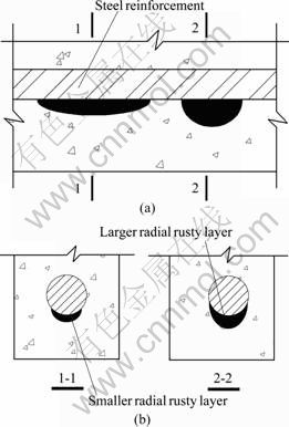
Fig.1 Local longitudinal and radial non-uniform corrosions in practical engineering: (a) Longitudinal non-uniform corrosion; (b) Radial non-uniform corrosion
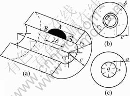
Fig.2 Three-dimensional model of non-uniform corrosion induced cracking of RC cover
If the concrete cover size, the radius of reinforcement bar, and the thickness of local rusty layer in Fig.2 are fixed, the stress intensity factor KI will be the maximum value on the end of elliptical minor axis, which can be expressed as
![]() (1)
(1)
As a result, only the stress intensity factor on the end of elliptical minor axis will be considered. For the deepest point A illustrated in Fig.2, the stress intensity factor [9] can be evaluated as
![]() (2)
(2)
where
![]() (3)
(3)
 (4)
(4)
 (5)
(5)
The parameters MiA were obtained by
 (6)
(6)
The geometry correction factors, Y0 and Y1, are expressed as
 (7)
(7)
where Ai and Bi are gained by
 (8)
(8)
 (9)
(9)
Q is the elliptical crack shape factor:
![]()
![]() (10)
(10)
When the value of stress intensity factor reaches the fracture toughness, the crack starts to propagate. Double-K fracture criterion for mode I crack of concrete can be represented as follows [10-12]:
1)![]() no crack propagation;
no crack propagation;
2)![]() steady crack propagation;
steady crack propagation;
3)![]() unsteady crack propagation.
unsteady crack propagation.
where![]() is the stress intensity factor expressed in Eq.(2),
is the stress intensity factor expressed in Eq.(2), ![]() is the initial fracture toughness and
is the initial fracture toughness and ![]() is the unstable fracture toughness which are the so-called double-K fracture parameters. In order to gain the fracture parameters of corrosion-induced cracking, one should consider the size effect of these parameters because the thickness of the concrete cover is generally less than 100 mm in practice. In the work, the concrete cover around the corroded reinforcing bars is modeled as a fixed beam subjected to uniform inner pressure, as shown in Fig.3, to consider the size effect. This not only expresses the actual stress state of the concrete cover, but also effectively accords with the shape of three-point bending notched beam which is used to evaluate the double-K fracture parameters. As a result, the size effect and boundary effect of corrosion-induced concrete cover cracking can be well understood. The fracture toughness of corrosion-induced cracking after considering the size effect can be expressed as
is the unstable fracture toughness which are the so-called double-K fracture parameters. In order to gain the fracture parameters of corrosion-induced cracking, one should consider the size effect of these parameters because the thickness of the concrete cover is generally less than 100 mm in practice. In the work, the concrete cover around the corroded reinforcing bars is modeled as a fixed beam subjected to uniform inner pressure, as shown in Fig.3, to consider the size effect. This not only expresses the actual stress state of the concrete cover, but also effectively accords with the shape of three-point bending notched beam which is used to evaluate the double-K fracture parameters. As a result, the size effect and boundary effect of corrosion-induced concrete cover cracking can be well understood. The fracture toughness of corrosion-induced cracking after considering the size effect can be expressed as
 h��2 m, 0.013��Cv��0.230 (11)
where ![]() is the fracture toughness needed in this work. h, V,
is the fracture toughness needed in this work. h, V, ![]() and Cv are, respectively, the height, volume, fracture toughness and its coefficient of variation of three-point bending notched beam.
and Cv are, respectively, the height, volume, fracture toughness and its coefficient of variation of three-point bending notched beam.
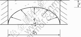
Fig.3 Fixed-beam model of concrete cover subjected to radial pressure
The initial threshold expansion pressure qini, deduced from the initial fracture toughness ![]() of corrosion-induced cracking, means the time when the corrosion-induced pressure reaches the point at which the propagation of corrosion-induced crack commences. In the same way, when the corrosion-induced pressure arrives at the threshold cracking pressure, qun, deduced from the unstable fracture toughness
of corrosion-induced cracking, means the time when the corrosion-induced pressure reaches the point at which the propagation of corrosion-induced crack commences. In the same way, when the corrosion-induced pressure arrives at the threshold cracking pressure, qun, deduced from the unstable fracture toughness ![]() of corrosion-induced cracking, the concrete cover cracks.
of corrosion-induced cracking, the concrete cover cracks.
According to Eq.(2), the initial threshold pressure qini and the threshold cracking pressure qun can be evaluated by the following expression (in order to shorten the length of the paper, qini and qun are expressed as one symbol q, and the following other symbols such as u, Ms and tr, have the same simplification):
![]() (12)
(12)
When the surrounding concrete is subjected to a corrosion-induced pressure q, the radial displacement of concrete u at the surface of the reinforcing bars is given by
![]() (13)
(13)
where Eco=2.15��104 MPa, fcmo=10 MPa, fcm is specified for 28-day cylindrical compressive strength of cover concrete, �� is the Poisson ratio for concrete, and ��c is the creep coefficient for the cover concrete.
After u is gained, the mass of steel Ms per unit length of the reinforcement (mg/mm) consumed by the corrosion process is evaluated as [13]:
![]() (14)
(14)
where a is the ratio of molecular mass of iron to the molecular mass of corrosion products, a1 is the ratio of volume of expansive corrosion products to the volume of iron consumed in the corrosion process, and ��s is the mass density of reinforcing steel.
For a constant annual mean corrosion rate Jcor (��A/cm2), the time of corrosion tr (a) is given as [13]
![]() (15)
(15)
When q attains a critical value qcr so as to cause the cracking of cover concrete, the evaluated Ms corresponds to the loss of mass of steel at cover cracking Mscr, and the evaluated tr corresponds to the time to cover cracking tcr.
2.2 Verification of present model
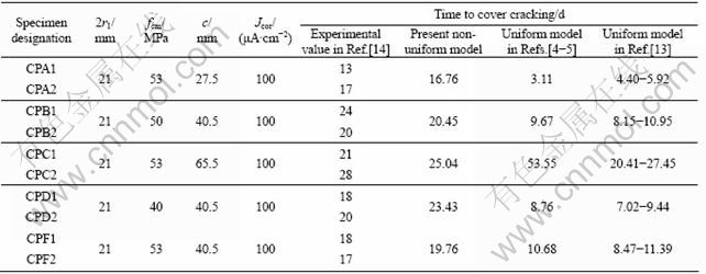
Five-year naturally exposed experiments and short- time indoor tests on the prediction of time to cover cracking conducted by LIU and WEYERS [13] and TORRES- ACOSTA and SAG??S [14], respectively, are used to verify the above model in this study. The experimental data of slabs in Ref.[13] and of cylindrical specimens in Ref.[14] are listed in Table 1 and Table 2. The computation parameters of the present model are described as follows.
Table 1 Results comparison of present model with experimental prediction in Ref.[13] and other models
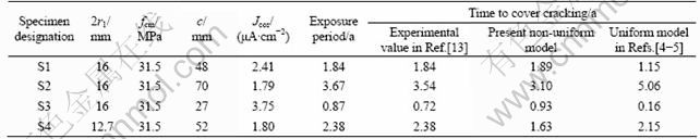
Table 2 Results comparison of present model with experimental prediction in Ref.[14] and other models
1) The stable values of ![]() and
and ![]() for concrete are taken as 1.034 MPa?m1/2 and 2.072 MPa?m1/2, respectively, based on the experimental results of 20 three-point beams provided by WU et al [15]. The corresponding coefficients of variation are 0.061 and 0.073. It should be noted that the influencing factors of fracture toughness such as the mixture ratio, the material composition in WU et al [15] are approximate with LIU and WEYERS [13], which also proves that the values of
for concrete are taken as 1.034 MPa?m1/2 and 2.072 MPa?m1/2, respectively, based on the experimental results of 20 three-point beams provided by WU et al [15]. The corresponding coefficients of variation are 0.061 and 0.073. It should be noted that the influencing factors of fracture toughness such as the mixture ratio, the material composition in WU et al [15] are approximate with LIU and WEYERS [13], which also proves that the values of ![]() and
and ![]() chosen in this work are credible. Other more experimental results also illustrate about the same stable fracture toughness values [10-12].
chosen in this work are credible. Other more experimental results also illustrate about the same stable fracture toughness values [10-12].
2) The values of a, b, ��, a1, ��c and �� are the same as those experimental or theoretical values adopted by LIU and WEYERS [13] and by BHARGAVA [4-5] for the convenience of results comparison to prove the precision of the present model.
The time to cover cracking predicted by the present method, compared with the experimental results of LIU and WEYERS [13] and TORRES-ACOSTA and SAG??S [14], are listed in Tables 1 and 2, respectively, together with model predictions of LIU and WEYERS [13], TORRES-ACOSTA and SAG??S [14], and BHARGAVA et al [4, 6-7]. As can be seen from Tables 1 and 2, the predicted time to cover cracking using the present method is in close agreement with the experimental results (the best difference is about 2.7%), which shows that the present model has good precision. At the same time, the present model obviously provides much better results than the models of LIU and WEYERS, TORRES-ACOSTA and SAG??S, and BHARGAVA et al (the maximal improving precision is about 48%), which are under the assumption of uniform corrosion. As a result, it is proved that the method provided by this work simulates coincidently with the non-uniform corrosion in practical engineering, and that the previous assumption of uniform corrosion around steel bar should be treated with discretion.
3 Influences of local rusty layer thickness on critical corrosion-induced cracking indexes
Different local rusty layer sizes of diametrical and longitudinal non-uniform corrosions will induce various mounts of expansion pressure, then result in variant phases of time to cover cracking. The influences of local rusty layer thickness on the threshold expansion pressure, critical mass loss of reinforcing steel, and time to cover cracking are depicted in Fig.4, Fig.5 and Fig.6, respectively. Local rusty layer thickness with sizes of a= 0.5 mm, 1 mm, a/b=0.1-1 mm are considered. Without loss of generality, the corrosion rate Jcor is deemed to be 1 ��A/cm2, which is the general mean value in nature [16], a concrete cover thickness and reinforcement bar diameter of 25 mm and 20 mm are adopted, respectively, and other parameters are the same as those described in Section 2. As can be seen from Figs.4-6, the local rusty layer thickness has a great effect on the critical mass loss of reinforcing steel, threshold cracking pressure and time to cover cracking. When the size of diametrical rusty layer a remains the same, the critical corrosion-induced cracking indexes increase with a/b increasing (that is to say, the size of longitudinal rusty layer b decreasing). For example, for local rusty layer thickness with size of a=0.5 mm, the time to cover cracking will increase by about one times when a/b changes from 0.1 mm to 1 mm. The three critical indices increase slowly when a/b is small and tends to rise sharply as a/b becomes larger. For the crack initiation of deepest point A on the minor axis, one can see that the three critical indices change approximately linearly. Similarly, When a/b remains the same, the critical corrosion-induced cracking indexes will change widely as a changes. Therefore, the uniform corrosion models to predict the time to cover cracking should be adopted cautiously.
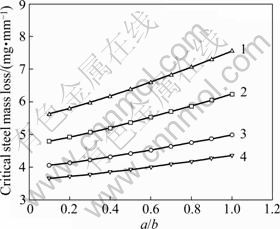
Fig.4 Influence of local rusty layer thickness on critical mass loss of reinforcing steel: 1��a=0.5 mm, time to cover cracking; 2��a=1.0 mm, time to cover cracking; 3��a=0.5 mm, crack initiation of point A on local rusty layer; 4��a=1.0 mm, crack initiation of point A on local rusty layer
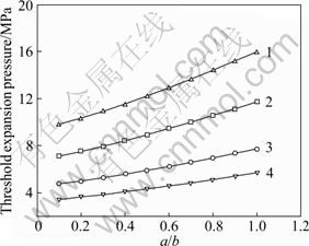
Fig.5 Influence of local rusty layer thickness on threshold expansion pressure: 1��a=0.5 mm, time to cover cracking; 2��a=1.0 mm, time to cover cracking; 3��a=0.5 mm, crack initiation of point A on local rusty layer; 4��a=1.0 mm, crack initiation of point A on local rusty layer
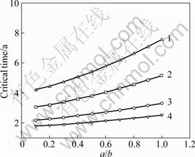
Fig.6 Influence of local rusty layer thickness on time to cover cracking: 1��a=0.5 mm, time to cover cracking; 2��a=1.0 mm, time to cover cracking; 3��a=0.5 mm, crack initiation of point A on local rusty layer; 4��a=1.0 mm, crack initiation of point A on local rusty layer
4 Conclusions
1) According to the diametrical and longitudinal non-uniform corrosions in practical corrosive RC structure, an analytic model for describing it is presented, which is in agreement with the non-uniform distribution of corrosion products around the steel bar in practical engineering. Comparisons with published experimental data show that the predictions given by the present model have a better precision than the previous theoretical corrosion models under the assumption of uniform corrosion.
2) The influence of local rusty layer thickness on the critical corrosion-induced crack index is analyzed. It is found that the local rusty layer thickness has great effect on the critical mass loss of reinforcing steel, threshold expansive pressure and time to cover cracking.
References
[1] PANTAZOPOLOU S J, PAPOULIA K D. Modeling cover-cracking due to reinforcement corrosion in RC structures [J]. Journal of Engineering Mechanics, 2001, 127(4): 342-351.
[2] TAMER E L, MAADDAWY, KHALED S. A model for prediction of time from corrosion initiation to corrosion cracking [J]. Cement & Concrete Composites, 2007, 29: 168-175.
[3] WANG Xiao-hui, LIU Xi-la. Bond strength modeling for corroded reinforcements [J]. Construction and Building Materials, 2006, 20: 177-186.
[4] KAPILESH B, GHOSH A K, YASUHIRO M, RAMANUJAM S. Analytical model for time to cover cracking in RC structures due to rebar corrosion [J]. Nuclear Engineering and Design, 2006, 236: 1123-1139.
[5] KAPILESH B, GHOSH A K, YASUHIRO M, RAMANUJAM S. Model for cover cracking due to rebar corrosion in RC structures [J]. Engineering Structures, 2006, 28: 1093-1109.
[6] LI Shu-cai, WANG Ming-bin, LI Shu-chen. Model for cover cracking due to corrosion expansion and uniform stresses at infinity [J]. Applied Mathematical Modelling, 2008, 32(7): 1436-1444.
[7] XU Gang, WEI Jun, ZHANG Ke-qiang, ZHOU Xi-wu. A calculation model for corrosion cracking in RC structures [J]. Journal of China University of Geosciences, 2007, 1(18): 85-89.
[8] YUAN Li-qun. The investigation and analysis of corroded and cracked reinforced concrete [D]. Xi��an: Xi��an University of Architecture & Technology, 2007. (in Chinese)
[9] MURAKAMI Y. Stress intensity factors handbook [M]. Japan: The Society of Materials Science, Japan & Elsevier Science Ltd, 2001: 349-351.
[10] XU Shi-lang, REINHARDT H W. Determination of double-K criterion for crack propagation in quasi-brittle fracture, Part ��: Compact tension specimens and wedge splitting specimens [J]. International Journal of Fracture, 1999, 98(2): 179-193.
[11] XU Shi-lang, REINHARDT H W. Crack extension resistance and fracture properties of quasi-brittle softening materials like concrete based on the complete process of fracture [J]. International Journal of Fracture, 1998, 92(1): 71-99.
[12] REINHARDT H W, XU Shi-lang. Crack extension resistance based on the cohesive force in concrete [J]. Engineering Fracture Mechanics, 1999, 64(5): 563-587.
[13] LIU You-ping, RICHARD E W. Modeling the time-to-corrosion cracking in chloride contaminated reinforced concrete structures [J]. ACI Materials Journal, 1998, 95(6): 675-681.
[14] TORRES-ACOSTA A A. Cracking induced by localized corrosion of reinforcement in chloride contaminated concrete [D]. Florida, USA: Department of Civil and Environmental Engineering, University of South Florida, 2005.
[15] WU Zhi-min, XU Shi-lang, DING Yi-ning. The double-K fracture parameter of concrete for non-standard three point bending beam specimens [J]. China Engineering Science, 2001, 3(4): 76-81. (in Chinese)
[16] MARK G S, ROSOWSKY D V. Time-dependent reliability of deteriorating reinforced concrete bridge decks [J]. Structural Safety, 1998, 20: 91-109.
(Edited by PENG Chao-qun)
Foundation item: Project(50925829) supported by the National Science Fund for Distinguished Young Scholars of China; Project(50908148) supported by the National Natural Science Foundation of China; Projects(2009-K4-23, 2010-11-33) supported by the Research of Ministry of Housing and Urban Rural Development of China
Received date: 2010-07-26; Accepted date: 2010-11-15
Corresponding author: ZHANG Xiao-gang, Associate Professor, PhD; Tel: +86-755-26535212; E-mail: bszxg@126.com
