
J. Cent. South Univ. (2016) 23: 1406-1415
DOI: 10.1007/s11771-016-3193-y

A new PMSM speed modulation system with sliding mode based on active-disturbance-rejection control
RONG Zhi-lin(������)1, 2, HUANG Qing(����)2
1. College of Electronics and Information Engineering, Tongji University, Shanghai 201804, China;
2. Zhuzhou CSR Times Electric Co., Ltd., Zhuzhou 412001, China
 Central South University Press and Springer-Verlag Berlin Heidelberg 2016
Abstract:
A sliding mode and active disturbance rejection control (SM-ADRC) was employed to regulate the speed of a permanent magnet synchronous motor (PMSM).The major advantages of the proposed control scheme are that it can maintain the original features of ADRC and make the parameters of ADRC transition smoothly. The proposed control scheme also ensures speed control accuracy and improves the robustness and anti-load disturbance ability of the system. Moreover, through the analysis of a d-axis current output equation, a novel current-loop SM-ADRC is presented to improve the system��s dynamic performance and inner ability of anti-load disturbance. Results of a simulation and experiments show that the improved sliding-mode ADRC system has the advantages of fast response, small overshoot, small steady-state error, wide speed range and high control accuracy. It shows that the system has strong anti-interference ability to reduce the influence of variations in rotational inertia, load and internal parameters.
Key words:
disturbance rejection; auto tuning; permanent magnet synchronous motor; speed modulation system��
1 Introduction
Motor control is a key technology in high-performance servo drives. As a typical nonlinear complex control objective, a PMSM has multivariable, strongly coupled nonlinear and variable parameters that make it difficult to meet the requirements of high- performance control for traditional vector control [1-3].
With the development of nonlinear control theory, various effective control strategies based on vector control have made it possible to realize high- performance control of the PMSM governing system. Most of these strategies utilize inner and outer loop controllers, such as adaptive neural network control [4], fuzzy PID control [5-6], sliding-mode variable-structure control (SMVSC), and active-disturbance-rejection control [7]. Among them, SMVSC has stronger adaptability and robustness on variation of parameters for system. However, the discontinuity caused by switch motion, chattering still exists in the SMVSC system [8]. To solve this problem, in Refs. [9-10], an additional integral part is added to the speed loop of the sliding-mode controller. In Refs. [11-12], an adaptive SMVSC is proposed to improve the gain of the controller, which gives the system the ability to self-regulate mismatches and uncertain disturbances. A novel nonlinear speed control that uses sliding-mode control and disturbance compensation techniques is adopted in Ref. [13]. However, the above methods cannot remove the system chattering caused by load torque mutation and parameter changes in low or ultra-low speed control systems. Hence, to obtain more accurate position control results, a more effective control strategy is needed to solve the speed loop control problem in the PMSM.
ADRC is a novel robust control method developed from nonlinear PID that can automatically detect and compensate for external disturbances independent of control objectives. However, although ADRC has strong adaptability and robustness, there are many adjustable parameters that lead to poor operation [14]. In Refs. [15] and [16], a fuzzy logic control is used to optimally estimate and automatically adjust parameters, which can improve the low-speed control performance of the motor. Furthermore, the speed and torque of the system can be effectively controlled without any parameter turning for the no-manual-tuned active-disturbance-rejection control (NMT-ADRC) developed in Ref. [17]. However, because of the influence of load torque mutation, moment of inertia, friction, the two abovementioned methods have poor anti-interference ability and large overshoot in the high-speed control of an AC servo system, which makes it difficult to meet the requirement of high steady-state accuracy.Combining the advantages of SMVSC and ADRC, a sliding mode-ADRC (SM-ADRC) for the PMSM is proposed in this work. In our method, the features of the original ADRC can be well preserved. Meanwhile, the process of parameter adjustment runs more smoothly. Compared with a traditional ADRC, the improved method has the features of fast response speed, non-overshoot, high static precision, wide speed range, and strong robustness with regard to load and system disturbance.
2 Mathematical model of PMSM
A salient-pole-rotor PMSM (SPMSM) driven by three-phase sinusoidal current is used as the control objective for this system. Assume that Ld=Lq and that there are no damper windings in the rotor. The positional relationships between the coordinate axes are shown in Fig. 1.
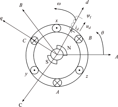
Fig. 1 Schematic diagram of coordinate axes
Given the stator current, when the speed is below the basic speed, the state equations of the PMSM in a synchronous coordinate system can be described as [18-19]
 (1)
(1)
where id and iq are the stator currents of the d- and q-axes components, respectively; ud and uq, respectively are the stator voltages of the d- and q-axes components; �� is the rotor speed; Rs is the stator resistance; L is the rotor inductance of the d-q axes; ��f is the rotor flux of the permanent magnet; TL is the load torque; Te is the electromagnetic torque; J is the rotor inertia; B is the friction coefficient; np is the pole pair;  is the angular speed of the rotor.
From Eq. (1), it can be seen that the d-q axes components of the stator current determine the magnitude of the electromagnetic torque. The torque control of the AC PMSM can be achieved by controlling the stator current in the vector control of the PMSM. Since Te changes with iq in the control system, the vector control can be realized by controlling iq.
3 Mathematical model of SM-ADRC
3.1 Mathematical model of ADRC
The ADRC is composed of a tracking differentiator (TD), extended state observer (ESO), and nonlinear states error feedback (NLSEF). In this work, a second- order ADRC is developed by using an active- disturbance-rejection speed loop that combines the speed and current loops [20-22].
A key component of ADRC is its capability to automatically compensate for disturbance estimations. By selecting an appropriate TD, ESO, nonlinear function, and parameters of NLSEF, the state equations of the second-order control objective can be described as follows:
 (2)
(2)
where u(t) is the system control value; �� is the output of the control objective; b is the gain of control quantity; the known value f(��z1, ��z2) is the internal disturbance of the system; the unknown variable  is the external disturbance of the system. The sum of the internal and external disturbances constitutes the total disturbance of the system.
Second-order ADRCs of PMSM equations are designed as follows:
1) Given an input signal of motor speed ��*, the linear differential-tracker function is given as follows:
 (3)
(3)
where ��v1 is the tracking signal of ��*; ��v2 is the differential signal of ��v1; the adjustable parameter R is the speed factor. The greater the value of R, the faster the signal tracking.
2) ESO is used to transform a nonlinear uncertain object with an unknown disturbance into an integral tandem-type object. According to the actual output �� and the d- or q-axis voltage u(t), the nonlinear ESO equations can be described as follows:
 (4)
(4)
where ��z1 is the track signal of system output ��; ��z2 is the differential signal of ��z1; z��3 is the estimation of the unknown disturbance; ����1 is the error signal. The three adjustable parameters ��01, ��02, and ��03 are output- error-correction gains.
3) NLSEF is the nonlinear combination of errors between derivatives of all orders and estimations of state variables, which come from the TD and ESO, respectively. NLSEF and the total disturbance compensation of the ESO together constitute the control volume. The equations of NLSEF are as follows:
 (5)
(5)
where e��0, e��1, and e��2 are, respectively, the error, its differential and second differential; ��1, ��2, and ��0 are the error, its differential and second differential gains, respectively. From Eq. (5), if the load disturbance of the motor a(t) can be effectively estimated according to the ESO, the effect of the disturbance can be reduced.
The optimal integrated control function fal(��) can be expressed as
 (6)
(6)
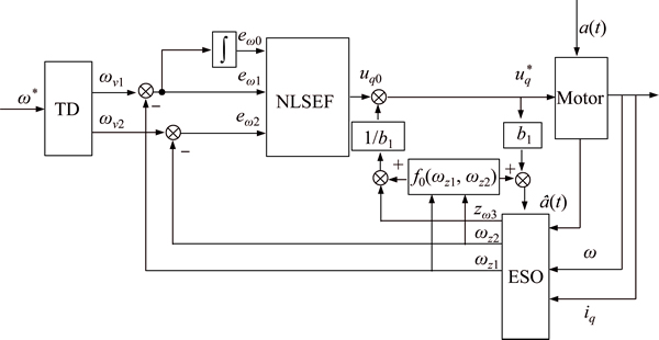
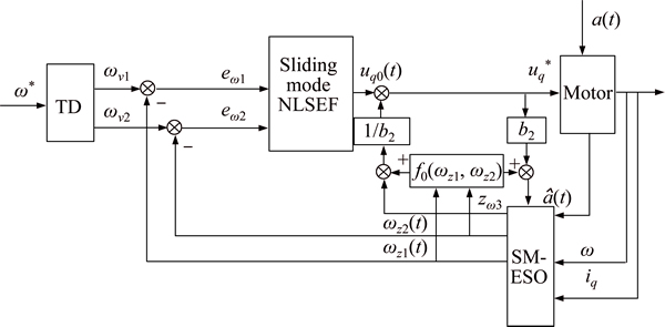
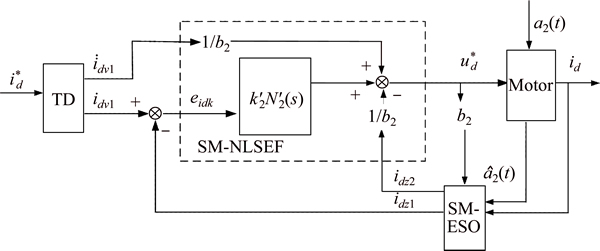
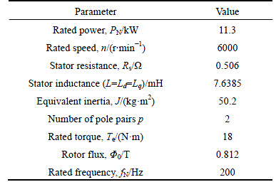
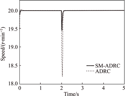
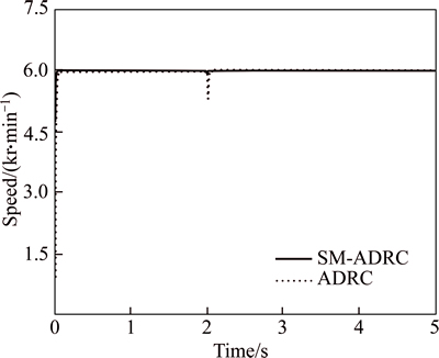
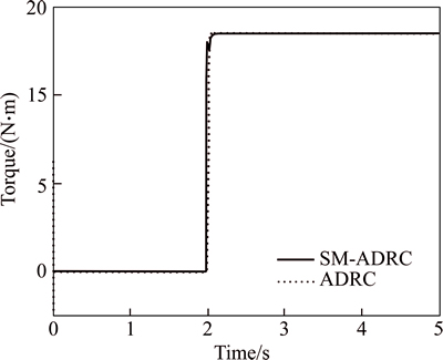
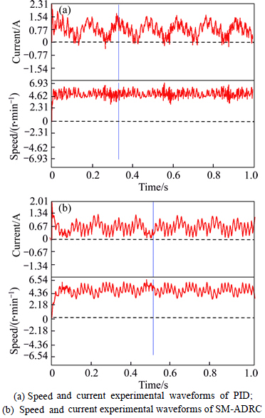
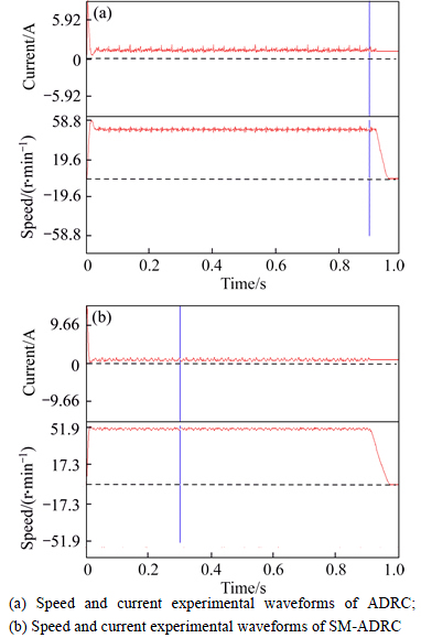
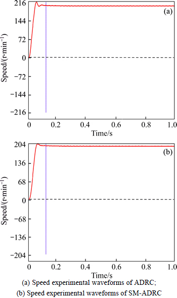
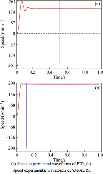
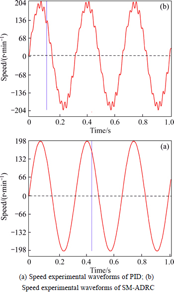
where a is the nonlinear factor, 0 The structure of a typical second-order ADRC is shown in Fig. 2. As we can see from Fig. 2, by estimating the state variables of the control object and compensating for the real-time total disturbance with the ESO, an appropriate NLSEF can be determined. 3.2 Mathematical model of sliding-mode ESO Sliding mode control (SMC) is a type of variable- structure nonlinear control strategy. When the system state changes, it can force the system to be stable in accordance with a predetermined sliding mode. Since the design of the sliding mode does not rely on any variables of the control objective, the disturbance caused by the variation of parameters and loads can be reduced. In addition, the SMC system has the characteristics of fast response, high static precision, and smooth torque [23-24]. Considering the motor speed regulation system as a single-input/output system, the SMC is designed as follows: 1) The stability of the sliding mode depends on a switching vector function s(x). Let the sliding mode switching vector function be as follows: where xi=x(i-1) (i=1, 2, ��, n) are system states and their all-order derivatives. Suitable constants c1, c2, ��, cn-1 are selected to construct a stable sliding mode. 2) Design an appropriate approach control rate to ensure that the sliding mode moves along the switching section s(x)=0. Combining the ADRC and SMC, Eq. (4) can be replaced by Fig. 2 Block diagram of a typical second-order ADRC controller Let Combining Eqs. (2), (4) and (8), the following equations can be obtained: A suitable control function g(����) is used to make the sliding-mode ESO stable. For a system described by Eq. (9), the sliding-mode switching vector function is designed as Set an appropriate c1 and c2 to make a polynomial p3+c2p2+c1p+1 (p is a Laplace operator) to satisfy the Hurwitz stability with a large stability margin. Let where k1 is an adjustable parameter, and sign(��) is the switching function. The proof of stability is as follows: Substituting Eq. (9) into the differential of s(x), we can obtain: Next, substituting Eqs. (11) into (12), one can obtain: Let k>A, then where the adjustable parameter ��1 is a smaller positive constant. Here, the function N(s) is used to maintain a continuous control volume to reduce chattering. 3.3 Mathematical model of sliding-mode NLSEF From Eqs. (3), (4)and (5), ��z1 and ��z2 can accurately track the state valuables �� and The nonlinear configuration of the error is used to realize control of the nonlinear state error feedback. To guarantee the stability of the system Eq. (14), the control volume is designed with a sliding-mode function: where k2 is an adjustable parameter, and N2(s) is the relay characteristic function. The selection of constant c1 and the sliding mode, and the analysis of the stability, are discussed in section 3.2. The above analysis shows that a sliding-mode ESO and NLSEF have two adjustable parameters independent of the order of the controlled system in the improved SM-ADRC. Compared with a typical ADRC, the improved method with fewer adjustable parameters makes parameter tun easier. 4 SM-ADRC speed control system of PMSM 4.1 Speed current loop controller based on SM-ADRC In a synchronous rotating coordinate system, a second-order dynamic equation of the speed current loop for a PMSM can be rewritten as Let The above equation can be simplified as where the system disturbance fq is the known, and the load disturbance a(t) is the unknown. The state equations of the speed current loop are given as follows: In Eq. (18), In an ADRC, a smooth tracking signal ��v1 and its differential ��v2 can be determined by using a TD. The system state values ��z1, ��v2 and the real-time disturbance z��3 are estimated by the sliding-mode ESO. The feedback from [z��3+f0(��z1, ��z2)]/b is used to compensate for the disturbance. The ADRC has a feedback structure that automatically compensates for the disturbance. In practice, the compensation control variable is given by where uq0(t) is a real-time control variable. Nonlinear feedback from state errors e��1, e��2, and e��0 is used to transform the nonlinear control system into a series-type integrator linear control system, and to determine the control volume of the tracing value. A nonlinear sliding-mode NLSEF (see Eq. (14)) is used to achieve the SM-ADRC. 4.2 Direct-axis current controller based on SM-ADRC As we can see from Eq. (1), the coupling effect Let b2=1/Ld; fd=-Rsid/Ld, the equation of the d-axis current can be described as follows: where fd is the known disturbance of the system, and a2(t) is the unknown external disturbance. The disturbance of the current loop can be effectively estimated by using the two parts above. By compensating for the disturbance, the system has good anti-interference abilities to reject the input voltage disturbances. According to the first-order linear differential tracker and Eqs. (8), (11), and (19)-(21), an SM-ADRC control structure for the d-axis current loop is available as shown in Fig. 4. The design of the direct axis current controller is similar to that of the speed current loop controller. The major difference is that the former is a first-order controller with fewer adjustable parameters. Hence, adjusting the parameters is more convenient. Moreover, the proposed controller can obtain good dynamic performance and can make the system more stable. Fig. 3 Speed current loop overall block diagram of SM-ADRC controller Fig. 4 d-axis current loop SM-ADRC control structure The entire system structure of the SM-ADRC speed control for a PMSM is shown in Fig. 5. The transition process can be smoothly controlled by the TD, which provides for rapid system response without overshoot. The application of a sliding-mode ESO can help us to obtain both the observation of state variables and system disturbances such as the disturbance caused by variations in the moment of inertia, stator resistance, and inductance, as well as other unknown external disturbances such as load disturbances. By using a sliding-mode NLSEF, the system can compensate for all types of disturbances. In addition, the presented SM-ADRC can realize nonlinear control for the speed and current signal, that is, ��small error large gain; large error small gain��. The SM-ADRC developed from a typical ADRC can realize optimal control across a wide range. The improved controller can not only preserve the original properties of the ADRC, but also reduce the number of adjustable parameters. Moreover, steady-state accuracy and speed-control accuracy are both improved. More important, the problem of system chattering is successfully resolved. A double closed-loop vector control construction with id=0 is used in Fig. 5. This is called a speed current loop, which is a novel speed current SM-ADRC that integrates the speed and current loop together. A d-axis current loop also adopts this novel controller. Compared with a typical ADRC, the SM-ADRC has fewer control links and a better control strategy. Furthermore, the SM-ADRC improves system anti-interference and stability. 5 Results and analysis of simulation and experiment To examine the control performance of the SM-ADRC for a PMSM, a numerical simulation was carried out by using MATLAB/Simulink. Furthermore, an actual self-developed frequency conversion control system is developed to compare a typical ADRC with an SM-ADRC for PMSM control. The simulation and experimental parameters of the PMSM are listed in Table 1. Through repeated adjustment, parameters in each part of the controller can be estimated and shown as follows: The parameter in the TD is R=2000. The parameters of the sliding-mode ESO and NLSEF can be ��1=0.05, ��2=0.025, k1=35, and k2=25. The parameters for the current loop can be R=1300, The simulation waveforms under low speed are shown in Fig. 6, where speed n=20 r/min, and torque increases from 0.334 N��m to 18 N��m at t =2 s. It can be seen from this figure that the SM-ADRC has better starting characteristics and robustness under low speed. Figure 7 shows high-speed response waveforms where speed n=6000 r/min and torque increases from 0.334 N��m to 18 N��m at t=2 s. The results show that the SM-ADRC has better dynamic/static performance, anti-interference, and speed control accuracy under high speed. In addition, the SM-ADRC exhibits a good adaptive performance. Electromagnetic torque contrast waveforms are shown in Fig. 8. When the motor starts, the electromagnetic torque of the SM-ADRC is less than that of a typical ADRC, and there is almost no pulsation in the steady state. At t=2 s, the electromagnetic torque response of the SM-ADRC can track the given value closely and quickly. Therefore, system power consumption and disturbances from electromagnetic and load torque can be dramatically reduced. Next, we compare the practical performances of controllers among a typical ADRC, PID, and SM-ADRC. The experimental current and speed waveforms are displayed by CCS. As shown in Fig. 9, when the motor starts with non-load and runs at a low speed of 5 r/min, the SM-ADRC has less current torque pulsation. This shows that the SM-ADRC has better control performance under low speed. As a result, faster positioning of the motor can be achieved for a double closed loop. Fig. 5 System structure of SM-ADRC speed control for PMSM Table 1 PMSM parameters for simulation and experiment Fig. 6 System response comparison of waveforms at low speed Fig. 7 System response comparison of waveforms at high speed Fig. 8 Electromagnetic torque comparison of waveforms Fig. 9 Comparison of SM-ADRC and PID at 5 r/min: Starting the motor under conditions of no load and 50 r/min speed, the speed and current waveforms are shown in Fig. 10. The results show that the motor, when it starts, has a faster speed and less overshoot under the control of the SM-ADRC. Moreover, the motor has fewer current harmonics and a smaller current torque as id=0. Starting the motor under conditions of no load and 6000 r/min speed, while maintaining the current operation for 1 min, the resulting speed and current waveforms are shown in Fig. 11. The results show that the control performance of the ADRC and SM-ADRC is close to each other. However, the system controlled by the SM-ADRC has achieved a faster step response without overshoot. Moreover, the ADRC has larger torque ripple at the starting point, and chattering occurs if the motor works at high speed for a long time. By contrast, the system can continuously run under 6000 r/min with high steady-state accuracy and smooth torque based on the performance of the SM-ADRC. In addition, the system can make motor stop quickly and stably to guarantee the reliability and stableness of system. Fig. 10 Comparison of SM-ADRC and ADRC at 50 r/min: Fig. 11 Comparison of SM-ADRC and ADRC at 6000 r/min: In the following experiments, the speed response under various actual situations is considered. Let the moment of inertia be 1.48��10-2 kg��m2, and start the motor without load at a given speed of 200 r/min. Speed waveforms are shown in Fig. 12. It can be seen that the SM-ADRC has a smaller steady-state error and better tuning parameters. Hence, it has smaller overshoot and can provide a smoother transmission into the steady state. Fig. 12 Comparison of SM-ADRC and ADRC at 200 r/min and 1.48��10-2 kg��m2: When the moment of inertia changes from 1.48��10-2 kg��m2 to 7.4��10-3 kg��m2, the advantage of the SM-ADRC is easily identified from Fig. 13. Starting the motor under conditions of no load and 200 r/min speed, the results show that the SM-ADRC has smaller overshoot and stronger anti-interference ability. This means that the SM-ADRC is not influenced by external disturbances and has strong robustness. We used the following test conditions: the moment of inertia changes from 1.48��10-2 kg��m2 to 7.4��10-3 kg��m2, and the given speed is a sine wave whose amplitude and period are from -200 to 200 r/min and 0.3 s, respectively. From Fig. 14, the PID exhibits a large amount of chattering, while the SM-ADRC still has better following performance. Fig. 13 Comparison of SM-ADRC and PID at 200 r/min and 7.4��10-3 kg��m2: Fig. 14 Comparison of SM-ADRC and PID from -200 to 200 r/min and 7.4��10-3 kg��m2: 6 Conclusions 1) The parameters�� adjustable process can be smoothly controlled by a tracking differentiator (TD), which provides for rapid system response without overshoot. Furthermore, the improved method with fewer adjustable parameters makes parameter tun easier. 2) The application of a sliding-mode ESO can obtain state variables and the system disturbances such as the disturbances caused by variations in the moment of inertia, stator resistance, and inductance, as well as other unknown external disturbances such as load disturbances. 3) By using a sliding-mode NLSEF, all types of disturbances are compensated. Thus, the dynamic and static performance of the control system can be greatly improved. References [1] LI Shi-hua, ZONG Kai, LIU Hui-xian. A composite speed controller based on a second-order model of permanent magnet synchronous motor system [J]. Transactions of the Institute of Measurement and Control, 2011, 33(5): 522-541. [2] CHOI H H. Adaptive control of a chaotic permanent magnet synchronous motor [J]. Nonlinear Dynamics, 2012, 69(3): 1311- 1322. [3] HAN Jing-qing. From PID to active disturbance rejection control [J]. IEEE Transactions on Industrial Electronics, 2009, 56(3): 900-906. [4] YU Jin-peng, YU Hai-sheng, CHEN Bing, GAO Jun-wei, QIN Yong. Direct adaptive neural control of chaos in the permanent magnet synchronous motor [J]. Nonlinear Dynamics, 2012, 70(3): 1879- 1887. [5] DOGAN M, DURSUN, MUSTAFA. Application of speed control of permanent magnet synchronous machine with PID and fuzzy logic controller [J]. Energy Education Science and Technology, Part A: Energy Science and Research, 2012, 28(2): 925-930. [6] CHOI H H, JUNG J W. Fuzzy speed control with an acceleration observer for a permanent magnet synchronous motor [J]. Nonlinear Dynamics, 2012, 67(3): 1717-1727. [7] SU Y X, ZHENG C H, DUAN B Y. Automatic disturbances rejection controller for precise motion control of permanent-magnet synchronous motors [J]. IEEE Transactions on Industrial Electronics, 2005, 52(3): 814-823. [8] NAVANEETHAN S, JEROM J. Speed control of permanent magnet synchronous motor using power reaching law based sliding mode controller [J]. WSEAS Transactions on Systems and Control, 2015, 10: 270-277. [9] LIN F J, CHOU W D. An induction motor servo drive using sliding mode controller with genetic algorithm [J]. Electric Power Systems Research, 2003, 64(2): 93-108. [10] VU N T, YU D Y, CHOI H H, JUNG J W. T�CS fuzzy-model-based sliding-mode control for surface-mounted permanent-magnet synchronous motors considering uncertainties [J]. IEEE Transactions on Industrial Electronics, 2013, 60(10): 4281-4291. [11] XIA Cun-jian, WANG Xiao-cui, LI Shi-hua, CHEN Xi-song. Improved integral sliding mode control methods for speed control of PMSM system [J]. International Journal of Innovative Computing, Information and Control, 2011, 7(4): 1971-1982. [12] KUNG C C, CHEN T H. H�� tracking-based adaptive fuzzy sliding mode controller design for nonlinear systems [J]. IET Control Theory and Applications, 2007, 1(1): 82-89. [13] SUN Li, ZHANG Xia-guang, SUN Li-zhi, ZHAO Ke. Nonlinear speed control for PMSM system using sliding-mode control and disturbance compensation techniques [J]. IEEE Transactions on Power Electronics, 2013, 28(3): 1358-1365. [14] TANG Lin, LIU Xing-qiao, ZHU Li-ting. Study on three-motor synchronous system of fuzzy active disturbance rejection control [J]. Applied Mechanics and Materials, 2012, 224: 543-546. [15] GU Wen, WANG Jiu-he, MU Xiao-bin, XU Sheng-sheng. Speed regulation strategies of PMSM based on adaptive ADRC [J]. Advanced Materials Research, 2012, 466/467: 546-550. [16] LI Jin-hui, LI Jie, YU Pei-chang, WANG Lian-chun. Adaptive backstepping control for levitation system with load uncertainties and external disturbances [J]. Journal of Central South University, 2014, 21(12): 4478-4488. [17] LU Da, ZHAO Guang-zhou, QU Yi-long, QI Dong-lian. Fuzzy permanent magnet synchronous motor control system based on no manual tuned active disturbance rejection control [J]. Transactions of China Electrotechnical Society, 2013, 28(3): 27-34. (in Chinese) [18] HU Jian-jun, JI Yi, YAN Jiu-jiang. Parameter design and performance analysis of zero inertia continuously variable transmission system [J]. Journal of Central South University, 2015, 22(1): 180-188. [19] LI Shi-hua, LIU Zhi-gang. Adaptive speed control for permanent magnet synchronous motor system with variations of load inertia [J]. IEEE Transactions on Industrial Electronics, 2009, 56(8): 3050- 3059. [20] DU Ren-hui, WU Yi-fei, CHEN Wei, CHEN Qing-wei. Adaptive fuzzy speed control for permanent magnet synchronous motor servo systems [J]. Electric Power Components and Systems, 2014, 42(8): 798-807. [21] PILLAY P, KRISHNAN R. Modeling of permanent magnet motor drives [J]. IEEE Transactions on Industrial Electronics, 1988, 35(4): 537-541. [22] LIU Hui-xian, LI Shi-hua. Speed control for PMSM servo system using predictive functional control and extended state observer [J]. IEEE Transactions on Industrial Electronics, 2012, 59(2): 1171- 1183. [23] KIM Y C, CHO M T. Wide speed range for traction motor in braking force of electric braking control system [J]. Journal of Central South University, 2014, 21(10): 3837-3843. [24] QIAO Zhao-wei, SHI Ting-na, WANG Yin-dong, YAN Yan, XIA Chang-liang. New sliding-mode observer for position sensorless control of permanent-magnet synchronous motor [J]. IEEE Transactions on Industrial Electronics, 2013, 60(2): 710-719. (Edited by YANG Hua) Foundation item: Project(2011AA11A10102) supported by the High-tech Research and Development Program of China Received date: 2015-07-08; Accepted date: 2015-12-29 Corresponding author: RONG Zhi-lin, PhD, Professor; Tel: +86-18507333309; E-mail: 18507333309@163.com
 (7)
(7)
 and
and  in Eq. (2). Assume that a0(t) is bounded, and let |a0(t)|��A. The disturbance can not infinite in the motor system. Combining Eqs. (4) and (7), the following equations can be obtained:
 (8)
(8) (9)
(9) (10)
(10) (11)
(11)
 (12)
(12)

 (13)
(13) According to the Lyapunov stable requirement, the sliding-mode control system will enter the sliding surface. Furthermore, the sign(��) in Eq. (11) is replacement of the relay characteristic function.
 Thus, the state error of the input signal ��* can be reconstructed with e��1=��v1-��z1, e��2=��v2-��z2. Since ��v1=��v2, ��z1=��z2. Eqs. (3) and (5) can be rewritten as follows:
 (14)
(14) (15)
(15) (16)
(16)


 (17)
(17) (18)and its differential can be determined by a position sensor. Obviously, the above state equations are the same as Eq. (3). Similarly, according to Eqs. (4)-(6) and (10), a speed current SM-ADRC controller is designed as shown in Fig. 3. It is noted that the differential operator here is different from the PID controller��s, and the former��s goal is to suppress noise signals instead of to amplify them.
 (19)
(19) between iq and the d-axis can be regarded as disturbance a2(t) for the d-axis current loop. Then,
 (20)
(20) (21)
(21)
 =0.03,
  =0.015,
  =10, and
  =5.
=5.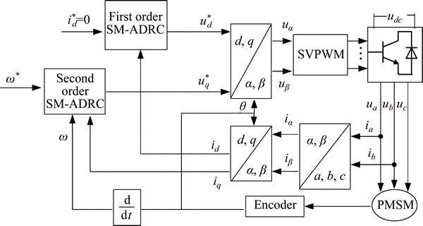

Abstract: A sliding mode and active disturbance rejection control (SM-ADRC) was employed to regulate the speed of a permanent magnet synchronous motor (PMSM).The major advantages of the proposed control scheme are that it can maintain the original features of ADRC and make the parameters of ADRC transition smoothly. The proposed control scheme also ensures speed control accuracy and improves the robustness and anti-load disturbance ability of the system. Moreover, through the analysis of a d-axis current output equation, a novel current-loop SM-ADRC is presented to improve the system��s dynamic performance and inner ability of anti-load disturbance. Results of a simulation and experiments show that the improved sliding-mode ADRC system has the advantages of fast response, small overshoot, small steady-state error, wide speed range and high control accuracy. It shows that the system has strong anti-interference ability to reduce the influence of variations in rotational inertia, load and internal parameters.
