
Trans. Nonferrous Met. Soc. China 23(2013) 3729-3738
Deformation mechanism of cold ring rolling in view of texture evolution predicted by a newly proposed polycrystal plasticity model
Hong-wei LI, Lu FENG, He YANG
State Key Laboratory of Solidification Processing, School of Materials Science and Engineering, Northwestern Polytechnical University, Xi��an 710072, China
Received 12 August 2013; accepted 30 October 2013
Abstract:
An explicit polycrystal plasticity model was proposed to investigate the deformation mechanism of cold ring rolling in view of texture evolution. The model was created by deducing a set of linear incremental controlling equations within the framework of crystal plasticity theory. It was directly solved by a linear algorithm within a two-level procedure so that its efficiency and stability were guaranteed. A subroutine VUMAT for ABAQUS/Explicit was developed to combine this model with the 3D FE model of cold ring rolling. Results indicate that the model is reliable in predictions of stress-strain response and texture evolution in the dynamic complicated forming process; the shear strain in RD of the ring is the critical deformation mode according to the sharp Goss component ({110}<100>) of deformed ring; texture and crystallographic structure of the ring blank do not affect texture type of the deformed ring; texture evolves rapidly at the later stage of rolling, which results in a dramatically increasing deformation of the ring.
Key words:
cold ring rolling; crystal plasticity; texture evolution; explicit algorithm;
1 Introduction
Cold ring rolling is a near-net-shape method that is widely used to produce seamless ring-shaped parts. This process is actually rather complicated with local loading but continuous deformation as the rotating ring passes between the rolls several times subjecting the ring to increasing levels of deformation. Therefore, during analysis of the process the stress state and the deformation of the whole ring must be considered and the region undergoing deformation makes the analysis more complicated [1,2]. Furthermore, the material in deformation region suffers from compressive stress due to the feeding of the idle roll and shear stress due to the frictional constraints applied by the driver and the idle rolls [3]. It is also significant that deformation compatibility of the material near the inner and outer margins contributes to the shear deformation in the center of the ring. Thus, the complicated deformation state and stress state result in complicated texture evolution, which influences, in turn, the deformation and thus the performance of the ring.
Therefore, the complicated deformation mechanism can be analyzed in view of texture evolution during the forming process. Crystal plasticity model serves as an effective tool to predict texture evolution in metal forming process [4]. In rate-dependent crystal plasticity (RDCP) theory, the key relationship between shear strain rate and the resolved shear stress on a slip system is a high-order nonlinear equation with an index of the reciprocal of material rate sensitivity coefficient. The high-order nonlinear equation makes the solution procedure quite unstable.
So, over the last few decades, many works have been done to develop reliable model and robust algorithm to enlarge its applications. Newton-Raphson (N-R) iteration was usually adopted in implicit algorithm for solving RDCP model due to its quadratic rate of convergence. Nevertheless, N-R iteration is rigorous on initial iterative value, which is very difficult to be estimated in FE simulation. So, many modified N-R iteration methods were developed [5,6]. However, these schemes involve iterations both at the local level to update the stress and globally to enforce equilibrium, requiring thus more computational effort than the explicit schemes [7]. Therefore, they usually were incompetent for simulation of dynamic complicated forming with massive elements and contact conditions due to huge consumed time. So, explicit models were paid much more attention, such as, the rate-tangent method [8], Euler forward method [9], Runge�CKutta scheme [7]. Although currently existed explicit models improve computational efficiency greatly, they are computationally unstable especially in dynamic complicated forming process because they are rigid in solution which results in computing failure. As results, the application of RDCP in FE simulation is limited to quasi-static deformation process, such as upsetting [10], equal channel angular extrusion [11] and cup drawing [9].
Therefore, this work will develop a new both efficient and stable polycrystal plasticity model so that cold ring rolling can be simulated by the polycrystal plasticity model. Thus, the complicated deformation of the ring can be analyzed in view of texture evolution.
2 Constitutive modeling of Taylor-type crystal plasticity
2.1 Taylor-type crystal plasticity foundations
The Taylor-type polycrystalline constitutive framework proposed by Taylor [12] is adopted here, expressed as
 (1)
(1)
where T(k) denotes the Cauchy stress in the kth crystal,  is the volume-averaged stress, N is the total number of grains comprising the material point, and wk is the volume fraction of each single grain.
The elastic constitutive relation for the stress in each grain is taken as
 (2)
(2)
where  is an elastic strain measure, R is a fourth-order elasticity tensor and I is the second-order identity tensor. T* has the relation with T as
 (3)
(3)
Here,  is the non-plastic deformation gradient with the plastic deformation gradient
  evolving as
  .
.
The plastic part of velocity gradient can be calculated through the crystal plasticity theory as
 (4)
(4)
Here,  and
and  are time-independent orthonormal unit vectors which define the slip direction and slip plane normal of the ��th slip system in a fixed reference configuration, and
  is the Schmid tensor.
The rate-dependent flow rule is adopted. The plastic shearing rate in the ��th slip system can be given by an exponential type law in terms of the resolved shear stress (RSS),  , and deformation resistance of the ��th slip system,
  , as
, as
 (5)
(5)
where  is a reference value, m is the strain rate sensitive coefficient of material, and the symbol sign stands for getting the sign symbol of .
In Eq. (5), RSS may be approximated by
 (6)
(6)
The Kocks-type hardening rule is adopted here. evolves as
 (7)
(7)
Here,  is the rate of strain hardening in slip system �� due to shearing in the slip system ��, which is related to a single slip hardening rate,
  , and the hardening matrix,
  , as
, as  ( no sum on �� here ) with
  ; h0, ss and a are hardening parameters. The hardening matrix, , given by Zhou et al [13] is adopted to account for the latent hardening and self-hardening of a crystal.
2.2 Linear incremental equations of new model
As described in section 2.1, the constitutive equations of RDCP are implicit with respect to  and
and  . Moreover, Eq. (5) indicates the high-level nonlinearity since m is usually very small (0.01-0.05 for metals). These characters bring trouble for numerical solution in aspects of computational efficiency and stability. To overcome the trouble, many algorithms (implicit and explicit ones) have been proposed, which have been discussed in section 1. Implicit ones suffer from much enough iteration so that they are with low efficiency, while explicit ones are proved very rigid needing very small step length (rate-tangent method and Euler forward method) and not self-starting (rate-tangent method). Therefore, as stated in section 1, the application of RDCP is limited in quasi-static forming process.
Here, a novel explicit model will be established based on the work in Ref. [5]. During the modeling, t and ��=t+��t denote the time at the start and the end of each increment, respectively. Taylor series expansion of Eq. (5), neglecting the high-order terms, is expressed as

 (8)
(8)
Meanwhile,  is assumed, and
  can be simplified since is unchangeable with deformation when calculations are carried out in the crystallographic system, which will be discussed in subsection 2.6.
So, the increments of stress and resistance of slip systems can be deduced based on the algorithm proposed by Kalidindi and ANAND [5]. They took the forms as

 (9)
(9)
and
 (10)
(10)
Here, there exists
 (11)
(11)
Since all variables at time t are known, Eqs. (9) and (10) are the equations set with the unknowns of  and
and  . For the purpose of efficiently solving, a two-level procedure is adopted here. Firstly, is fixed at its value at time t, Eq. (9) can be deduced and written in its components as

 (12)
(12)
in which
 (13)
(13)
Since both  and
and  can be calculated directly, Eq. (12) is a linear equation set with the unknowns of
  . Here, the complete pivot Gaussian elimination method is adopted for the solution. After getting , the second-level solving procedure starts. Equation (10) can also be rewritten into a linear equation set in the same way, expressed as
 (14)
(14)
with
 (15)
(15)
So, can also be updated with the new by the complete pivot Gaussian elimination method. Then, a recalculation loop is invoked for a new by the new until
 (16)
(16)
is satisfied. Here, s0 is the initial deformation resistance of slip systems, and all slip systems are assumed to have the same value.
2.3 Stress update system
Since vectors and tensors related to crystals are stored in the crystallographic coordinate (Cc), such as and R, while the ones related to deformation, such as F, E, T and Q, provided by the finite element method are stored in the global coordinate (Cg). As we all know, all tensors and vectors must be in the same system during constitutive update. Therefore, the transformation between systems for vectors and tensors is needed. Two ways exist for the transformation. One is to transfer the ones in Cc to Cg so as to perform constitutive update in Cg, and the other is to transfer the ones in Cg to Cc so as to perform constitutive update in Cc. However, the first way faces expensive computing cost since the sizes of internal variables for the update of tensors related to crystals increase with the increase of the number of elements (ne) and crystals (nc) at the level of ne��nc. So, all variables in Cg were transferred to Cc to carry out the constitutive update in this work for computational efficiency. In this case, tensors related to crystals are time-independent constants for all crystals so that there is much less calculation amount to do. Here, we have to mention that the obtained stress T and orientation update matrix F* are in Cc. Therefore, it is required to transfer them to Cg to return to finite element method and to account for texture update.
2.4 Texture evolution
Texture evolution is tracked through a rotation matrix Q, which is formed through three Euler angles in Kalidindi��s notation [5]. This matrix was defined to quantify the relation of vectors or tensors between. By virtue of this rotation matrix, there exist
 and
and  (17)
(17)
where Dg stands for a tensor in Cg and Dc stands for the one in Cc.
In order to track texture evolution, the matrix Q should be stored and updated step by step during forming process. The formula proposed by Kalidindi and Anand [5] is employed here as
 (18)
(18)
2.5 Model verification
According to the presented model, a user subroutine VUMAT was coded under the environment of ABAQUS/Explicit [14]. The proposed model is verified by the comparison of the predicted stress-strain responses and textures evolution with experiments. Here, OFHC copper, a FCC metal, was employed whose parameters are listed in Table 1. Calculations of the uniaxial compression, simple shear and plane strain compression were performed. There were 400 randomly oriented grains used in these simulations. The predicted stress-strain responses in uniaxial compression and simple shear, as illustrated in Figs. 1(a) and (b) respectively, show good agreement with experimental data [5]. In addition, the predicted texture in the plane strain compression with a 75% thickness reduction, as shown in Fig. 2, captures the most important features of the experimental texture [4,15], e.g. the presence of the minor Goss component and pronounced copper, S- and brass components. These results indicate that the present model is reliable in predictions of both stress response and texture evolution.
Table 1 Material constants of OFHC copper

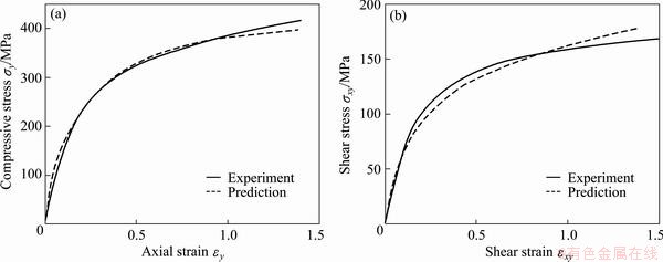
Fig. 1 Comparison of predicted stress-strain responses to experiments [5] in uniaxial compression (a) and simple shear (b)
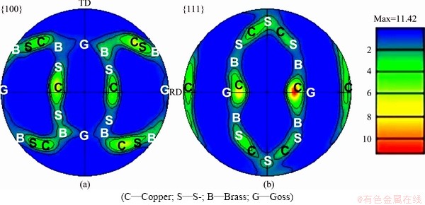
Fig. 2 Predicted texture and its important components in plane-strain compression (plate rolling) with 75% thickness reduction
3 Crystal-plasticity-based modeling of cold ring rolling
3.1 3D FE modeling of cold ring rolling process
Here, a 3D FE model of cold ring rolling with a rectangle section was created under the platform of ABAQUS/Explicit, as illustrated in Fig. 3. In the model, driver roll, idle roll and two guide rolls were all defined as rigid body; the ring blank was defined as a deformable body, which was meshed into 1280 C3D8R elements. When this process starts, the driver roll rotates actively at a speed of ��, the idle roll feeds in at a speed of v and rotates passively in the reverse direction to ��, and the two guide rolls rotate passively and move in terms of the growth of the ring, which provides suitable constraints on the ring to ensure the roundness of the ring. So, complex dynamic contacts are required. Here, four contact pairs were defined as: 1) DRCS-RECS, 2) IRCS-RICS, 3) GRCS1-RECS, and 4) GRCS2-RECS. Coulomb friction with the coefficient of 0.2 was assigned to the contact pairs of DRCS-RECS and IRCS-RICS, and no friction was assumed with GRCS1-RECS and GRCS2-RECS.
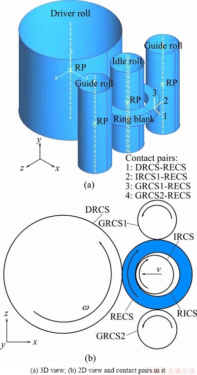
Fig. 3 3D FE model for cold ring rolling with rectangle section
It is mentionable that the movements of guide rolls play crucial effects on steady forming of the dynamic process. The guide rolls must touch the ring to provide a suitable constraint all the time, otherwise, the forming process will not go on steadily. Guo et al [16] defined the trajectory of guide rolls by considering theoretical rule of ring growth, which was verified by experiments. So, it was adopted in the present work.
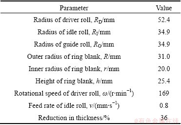
By considering the symmetrical deformation of the ring about the axial middle plane, one half parts above the middle plane was reserved in the model in order to save CPU time. The geometry and loading parameters used in the model are listed in Table 2.
Table 2 Parameters used in cold ring rolling model
3.2 Built-in polycrystal plasticity in cold ring rolling model
The presented polycrystal plasticity model was built in the 3D cold ring rolling model via an in-house code of the user material subroutine VUMAT. For the sake of the combination, the corotational coordinate system was defined in the ring blank. Under this local system, grain orientations were assigned. This helps to obtain the proper textures caused by the elasto-plastic deformation of the ring and avoid the influence of the ring movement. A set of grains with random orientations were assigned to each finite element. Therefore, each element represents the grains aggregate. The response of one element is the volume-averaged response of these grains. As commonly understanding, no less than 50 grains assigned to one element can effectively account for the stress response and texture evolution of grains aggregate.
3.3 Verification of combined model
3.3.1 Comparison of predicted ring growth with experimental data
Figure 4 shows the comparison of the outer diameters of the ring after cold rolling predicted by the present polycrystal plasticity model and the commonly used J2 plasticity model with experimental data. The span of each value in Fig.4 indicates the minimal and maximal diameters measured from the deformed ring so that the roundness of the ring can be calculated by ��=1-(Dmax- Dmin)/Dmin. It can be found that the prediction by the polycrystal plasticity model is closer (the error is 1.13%) to experimental data than that by J2 plasticity; the diameter predicted by the polycrystal plasticity model is smaller, while the one predicted by J2 plasticity is larger than the experimental one; the predicted ring roundness (denoted by ��D��0.45 mm) is a little worse than experimental one (��D��0.16 mm). The present model considers anisotropic deformation in grain level so that it obtained a smaller ring than that obtained by the isotropic J2 plasticity model. The slightly worse roundness obtained by both of the two constitutive models should be attributed to the definition of the trajectory of guide rolls in the geometry model. In brief, the comparison verifies the reliability of the combined model on deformation prediction in cold ring rolling process.
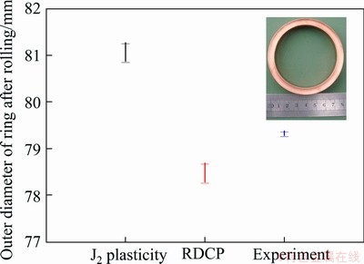
Fig. 4 Comparison of radial growth of ring predicted by present polycrystal plasticity model, J2 plasticity model and experiment
3.3.2 Comparison of predicted texture with experimental ones
The predicted texture in cold ring rolling process was compared with experimental ones carried out by Ryttberg et al [1] in order to verify the combined model in texture prediction in such a complex forming process. To this end, parameters of 100Cr6 steel (Table 3) and 12 {1 1 0}<1 1 1> slip systems for BCC metal were employed, and the initial ring blank was assigned a rather strong <111>//AD-fiber texture (Fig. 5(a)) to keep consistence with the experiment (Fig. 5(b)). Texture of the ring at the end of the rolling process was represented by pole figures, as shown in Figs. 5(c)-(f). Both the predictions and experiments show that the grains are clearly rotated compared with the initial texture, resulting in a sharp Goss component ({110}<100>). From these pole figures, the rotation was determined to be 30�� around the AD axis. This texture is well known to occur under shear load. The comparison verifies the reliability of the combined model on texture prediction in cold ring rolling process.
Table 3 Material constants of 100Cr6 steel
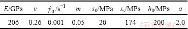
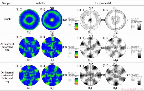
Fig. 5 Comparison of predicted texture with experimental result [1] of 100Cr6 steel ring after cold rolling
4 Results and discussion
4.1 Analysis of deformation and stress state in view of texture
As stated in the section of introduction, ring rolling process is rather complicated. Guo et al [17] pointed out that there exist three flow behaviors during the cold ring rolling: 1) in the thickness direction, leading to thinning in the thickness of the ring blank; 2) in the circumferential direction, resulting in expanding the diameter of the ring blank; and 3) in the axial direction, resulting in spread in height of the ring blank. In view of texture after cold rolling, material in the process mainly suffers shear load rather than plane-strain compressive load via the texture in Fig. 5 in comparison with Fig. 2. It can be interpreted by the metal flow behavior illustrated in Fig. 6. Material on the inner and outer surfaces of the ring in the illustrated deformation zone suffers compressive load by the feed of the idle roll and tangential force driven by friction, which forces the material flow in the circumferential and axial directions. However, the flow velocity in the circumferential direction (neglecting the flow in the axial direction) does not keep consistent across the ring section, as illustrated by the arrows in Fig. 6(b), since the material between the inner and outer surfaces is driven by the flow of the material on the two surfaces. The unequal flow velocity results in a large strain (shear strain) at the center of the ring (Fig. 6(c)) owing to deformation compatibility. That is why the texture intensity at the center is higher than that on the internal surface (Fig. 5).
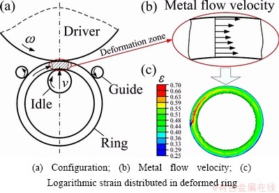
Fig. 6 Illustration of deformation mechanism in cold ring rolling
It can also be corroborated from the microstructure evolution. Figure 7 shows the microstructures sampled at the center of the ring before and after rolling. It can easily found the grains were refined and many oriented lath-shaped grains were generated after rolling. It may also be attributed to the large shear strain at the center of the ring during rolling. Such microstructure evolution, driven by macroscopic deformation, is the intrinsic causes for the enhanced texture at the ring center.
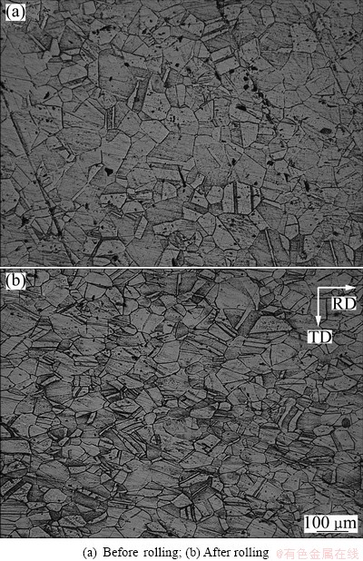
Fig. 7 Microstructures sampled at center of ring
4.2 Effect of initial texture and crystallographic structure
Some simulations were carried out on the basis of a randomly oriented texture (i.e. no texture), as shown in Fig. 8(a). The final texture after cold rolling is provided in Fig. 8(b). No significant difference in texture type, except for texture intensity, can be found by comparing the texture in Fig. 8(b) with that in Fig. 5(c). That is to say the initial texture does little affect the texture evolution in cold ring rolling process.
Some simulations of cold ring rolling with a FCC structured metal (OFHC copper) were performed as well. Texture is presented in Fig. 9. Compared with Fig. 8, Fig. 9 shows consistent but slightly weaker texture. It can be attributed to the less slip systems in FCC metal than in BCC metal. Many enough slip systems in BCC metal make grain rotate much easy. Anyway, the same deformation process leads to consistent texture evolution in spite of FCC or BCC metal, which verifies further the reliability of the present model on texture prediction.
4.3 History of texture evolution in forming process
During the cold ring rolling process with a rectangle-section OFHC copper ring blank, texture evolves with forming process, as shown in Fig. 10. In Fig. 10, the reductions in ring thickness are 7.3%, 14.5% and 21.8%, respectively. It can be found the observable texture was formed when the thickness reduction reaches 21.8%. It tells that the deformation rate increases with the processing instead of keeping constant rate, which can be verified by the evolution of equivalent plastic strain, as shown in Fig. 11. The deformation of the ring can be easily divided into three stages. In stages I and II, the deformation increases linearly but with increasing rate from stage I to stage II. In stage III, the deformation increases almost along a quadratic curve. This can also be interpreted by texture evolution. From Fig. 10, it can be found most of grain orientations turn to be parallel to rolling direction (RD) at the reduction of 21.8% since the strongest texture is {101}//RD. These orientations make further deformation easy during ring rolling.
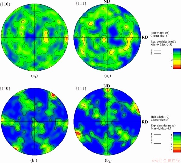
Fig. 8 Texture of deformed ring (b1, b2) with initial random texture of blank (a1, a2)
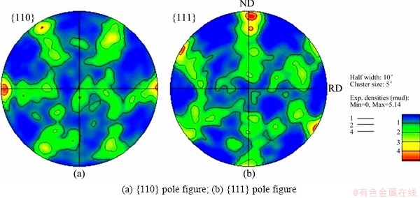
Fig. 9 Texture of deformed ring with FCC structured metal
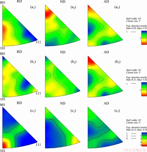
Fig. 10 Textures of ring denoted by inverse pole figures at thickness reduction of 7.3% (a1, a2, a3), 14.5% (b1, b2, b3), and 21.8% (c1, c2, c3)
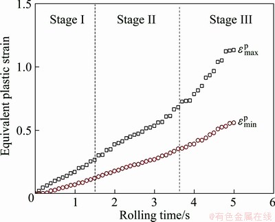
Fig. 11 Evolution of equivalent plastic strain of ring during cold rolling process
5 Conclusions
1) A new polycrystal plasticity model was created by deducing the explicit linear controlling equations within the framework of RDCP and adopting a two-level solution procedure. It was successfully applied to the complicated and dynamic ring rolling process for the first time. This verifies the high computational efficiency and stability of this model in simulations of large and complicated forming process with massive elements and contact conditions.
2) The comparison of the predicted results by the model with those in experiments illustrates that the model was reliable in predictions of both stress-strain response and texture evolution in both quasi-static simple deformation and dynamic complicated deformation.
3) The results show that the texture of the deformed ring is a sharp Goss component ({110}<100>), indicating the main deformation lies in shear strain in RD; texture intensity is higher at the center of ring than that on the surface, indicating a larger strain at the center of ring; initial texture and crystallographic structure do not affect texture type of the deformed ring; texture evolves rapidly at the later stage of rolling results in a dramatically increasing deformation of the ring at this stage.
References
[1] Ryttberg K, Knutson Wedel M, Recina V, Dahlman P, Nyborg L. The effect of cold ring rolling on the evolution of microstructure and texture in 100Cr6 steel [J]. Materials Science and Engineering A, 2010, 527: 2431-2436.
[2] QIAN Dong-sheng, HUA Lin, DENG Jia-dong. FE analysis for radial spread behavior in three-roll cross rolling with small-hole and deep-groove ring [J]. Transactions of Nonferrous Metals Society of China, 2012, 22(S2): s247-s253.
[3] WANG Min. Comparison of evolution laws of stress and strain fields in hot rolling of titanium alloy large rings with different sizes [J]. Transactions of Nonferrous Metals Society of China, 2011, 21(7): 1611-1619.
[4] HUANG Shi-yao, ZHANG Shao-rui, LI Da-yong, PENG Ying-hong. Simulation of texture evolution during plastic deformation of FCC, BCC and HCP structured crystals with crystal plasticity based finite element method [J]. Transactions of Nonferrous Metals Society of China, 2011, 21(8): 1817-1825.
[5] Kalidindi S R, Anand L. An approximate procedure for predicting the evolution of crystallographic texture in bulk deformation processing of FCC metals [J]. International Journal of Mechanical Sciences, 1992, 34(4): 309-329.
[6] Li H W, Yang H, Sun Z C. A robust integration algorithm for implementing rate dependent crystal plasticity into explicit finite element method [J]. International Journal of Plasticity, 2008, 24(2): 267-288.
[7] Raphanel J L, Ravichandran G, Leroy Y M. Three-dimensional rate-dependent crystal plasticity based on Runge-Kutta algorithms for update and consistent linearization [J]. International Journal of Plasticity, 2004, 41(22-23): 5995-6021.
[8] Peirce D, Asaro R J, Needleman A. Material rate dependence and localized deformation in crystalline solids [J]. Acta Metallurgica, 1983, 31(12): 1951-1976.
[9] Grujicic M, Batchu S. Crystal plasticity analysis of earing in deep-drawn OFHC copper cups [J]. Journal of Materials Science, 2002, 37: 753-764.
[10] CHENG Li-dong, WANG Zhen-long. Scale effect mechanism on micro rod upsetting deformation analyzed by crystal plasticity model [J]. Transactions of Nonferrous Metals Society of China, 2012, 22(10): 2444-2450.
[11] LI Sai-yi. Application of crystal plasticity modeling in equal channel angular extrusion [J]. Transactions of Nonferrous Metals Society of China, 2013, 23(1): 170-179.
[12] Taylor G I. Plastic strain in metals [J]. Journal of the Institute of Metals, 1938, 62: 307-324.
[13] ZHOU Y, NEALE K W,  L S. A modified model for simulating latent hardening during the plastic deformation of rate-dependent FCC polycrystals [J]. International Journal of Plasticity, 1993, 9(8): 961-978.
[14] ABAQUS [M]. Version 6.10. ABAQUS, Inc Providence, RI, 2010.
[15] BRONKHORST C A, KALIDINDI S R, ANAND L. Polycrystalline plasticity and the evolution of crystallographic texture in FCC metals [J]. Philosophical Transactions: Physical Sciences and Engineering A, 1992, 341(1662): 443-477.
[16] Guo L G, Yang H, Zhan M, Li H, Li L Y. Simulation for guide roll in 3D-FE analysis of cold ring rolling [J]. Materials Science Forum, 2004, 471-472: 760-764.
[17] Guo L, Yang H, Zhan M. Research on plastic deformation behaviour in cold ring rolling by FEM numerical simulation [J]. Modelling and Simulation of Materials Science and Engineering, 2005, 13: 1029-1046.
�����¾�������ģ��Ԥ��֯���ݻ��Ļ����������λ���
���ΰ���� 责��� ��
������ҵ��ѧ ����ѧԺ�����̼��������ص�ʵ���ң����� 710072
ժ Ҫ�����һ���µĶྦྷ������ģ���Դ�֯���ݻ��Ƕ��о������������̵ı��λ��ơ���ģ�����ھ����������ۿ����ͨ���Ƶ�һ�������������Ʒ��̽����ġ���ģ�Ϳ�����������ⷽ��ֱ����⣬������һ���������������̣�ȷ��ģ�ͼ����Ч�ʺ��ȶ��ԡ�����ABAQUS/Explicitƽ̨�������û������ӳ���VUMAT����ʵ�ָ�ģ���뻷��������ά����Ԫģ�͵Ľ�ϡ������������ģ����Ԥ�̬���ӳ��ι����е�Ӧ��Ӧ����Ӧ��֯���ݻ����涼�ǿɿ��ģ������ƻ����к�ǿ��Goss֯��{110}<100>��������������ļ��б����ǻ������������е���Ҫ���Σ�������֯���;���ṹ�����ƻ����е�֯�����͵�Ӱ�첻���������ĺ��ڻ���֯���ݻ�Ѹ�٣��������һʱ�ڻ����Ŀ��ٳ���
�ؼ��ʣ������������������ԣ�֯���ݻ�����ʽ�㷨
(Edited by Hua YANG)
Foundation item: Project (51175428) supported by the National Natural Science Foundation of China; Project (B08040) supported by Program of Introducing Talents of Discipline to Universities (��111�� Project), China
Corresponding author: Hong-wei LI; Tel: +86-29-88460212; E-mail: lihongwei@nwpu.edu.cn
DOI: 10.1016/S1003-6326(13)62923-4
Abstract: An explicit polycrystal plasticity model was proposed to investigate the deformation mechanism of cold ring rolling in view of texture evolution. The model was created by deducing a set of linear incremental controlling equations within the framework of crystal plasticity theory. It was directly solved by a linear algorithm within a two-level procedure so that its efficiency and stability were guaranteed. A subroutine VUMAT for ABAQUS/Explicit was developed to combine this model with the 3D FE model of cold ring rolling. Results indicate that the model is reliable in predictions of stress-strain response and texture evolution in the dynamic complicated forming process; the shear strain in RD of the ring is the critical deformation mode according to the sharp Goss component ({110}<100>) of deformed ring; texture and crystallographic structure of the ring blank do not affect texture type of the deformed ring; texture evolves rapidly at the later stage of rolling, which results in a dramatically increasing deformation of the ring.
