

Tendency of homogeneous radial deformation during electromagnetic compression of aluminium tube
YU Hai-ping(�ں�ƽ)1, LI Chun-feng(���)1, LIU Da-hai(����)1, MEI Xian(÷ ��)2
1. School of Materials Science and Engineering, Harbin Institute of Technology, Harbin 150001, China;
2. Computer Centre, Harbin University of Science and Technology, Harbin 150080, China
Received 10 October 2008; accepted 10 March 2009
Abstract:
Electromagnetic forming is one of the high-rate forming methods that can be extensively used to form and join axisymmetric metal sheet and tube. Tendency of homogeneous radial deformation during electromagnetic compression of aluminium tube was investigated through the design optimization method based on sequential coupling numerical simulation and experiments. The results show that the tendency depends on the length ratio of tube to coil (R), which has a critical value (Rc) corresponding to the relatively homogeneous radial deformation along axial direction. The tube length relative to Rc is insensitive to the discharge voltage. When R is greater than Rc, the deformed tube presents horn shape and the shorter coil makes for local deformation. If R is less than Rc, the deformed tube presents drum shape and the longer coil contributes to larger deformation at tube end. Rc increases with coli length and could approach to 1; inversely, it could approach to 0. These results indicate the design optimization method based on the sequential coupling numerical simulation is feasible, which can be used to realize the controllable and precise deformation of metal tube.
Key words:
homogeneous radial deformation; design optimization method; electromagnetic forming; aluminium tube;
1 Introduction
In view of the necessity of energy saving, limited amount of natural resources and growing environmental pollution, recyclable lightweight materials are gaining increasing importance in modern advanced manufacturing technologies and structural design. The lightweight, high strength materials, such as aluminium alloy and titanium alloy, have been widely used lately in the aerospace and automotive industries. The electromagnetic forming (EMF) has peculiar advantages over the conventional methods in forming the lightweight metal materials, because of improved strain distribution, reduction in wrinkling, active control of spring-back, less-contact forming and more manufacturing flexibility[1-4]. All these advantages make this method and its complex technology (e.g. electromagnetically assisted sheet metal stamping) become efficient ways to form aluminium tube and sheet metal[2, 5-6].
In conventional sheet metal stamping, one can estimate, by some simple formulae, the loading condition or press tonnage for the given material and part geometry. However, the relationships between electrical parameters (e.g. discharge voltage) and deformation of workpiece cannot be expressed and calculated by concise mathematic formulae during the EMF process, for the electromagnetic field and stress-strain field, and constitutive relations of materials and temperature field are coupled in the EMF process[5]. It is one of the reasons which make EMF process not compete with the classic and/or conventional forming methods. Although the finite element method (FEM) has been successfully used in the analysis of EMF process[4-5, 7-10], the effective prediction and optimization of the initial process parameters, such as the discharge voltage and the coil length for homogeneous radial deformation during electromagnetic tube forming, cannot be made by FEM or feasibly performed by experiment alone. Therefore, the investigations on the optimization of EMF process are necessary and important.
It has been known that the relationships between the tube and coil decide the time-space distribution of magnetic filed and magnetic force, which affects the magnitude and distribution of tube deformation. Among them, the length ratio of tube to coil is the crucial one[11]. MAMALIS et al[8] presented that the optimization analysis method, in combination with finite element analysis, dynamic design and numerical modeling, is used to solve many problems in metal forming. LU[12] indicated that, for the problems that are hard to abstract mathematical model and cannot be expressed by explicit function, the optimization analysis method based on finite element method is appropriate. In Ref.[13], the initial discharge voltage was forecasted by the design optimization method based on the sequential coupling numerical simulation. The maximum relative error between the experiments and forecast is 5.9%, which manifests that this method can be used for optimum design and analysis of EMF process.
As stated earlier, the researches on the numerical simulation of EMF have been extensively documented. However, few literatures reporting the homogeneous radial deformation were found. In the present work, the tendency of homogeneous radial deformation of aluminium tube and its affecting factors are investigated through the design optimization method based on the sequential coupling numerical simulation of EMF by using of FEM software ANSYS and experiments. This method can be used to realize the controllable and precise deformation of metal tube.
2 Experimental
2.1 Setup
The EMF machine was used in the experiments. Total capacitance of the capacitor bank is 702 ��F, which can be charged up to 10 kV. The tools are solenoid coils made of copper wire (lead section of 5.0 mm long and 3.0 mm wide) and insulation materials (nylon, ethoxyline resin, polyester resin, etc), whose geometrical parameters are presented in Table 1. The dimensions and shape of the electromagnetic tube compression system are shown in Fig.1, where the coils are coaxial and concentric with tubes.
Table 1 Geometrical parameters of coil for tube compression
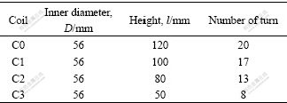
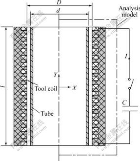
Fig.1 Dimensions of tube compression
A pulse of current running through the coil is the load in EMF, which is easily measured by experiment. The first period of the current is considered to be responsible for tube compression. In the analysis of electromagnetic forming process, the current is proximately expressed by Eq.(1), in which the inductance and damping exponent are obtained under the discharge voltage not high enough to form the tube:
![]() (1)
(1)
where U is the discharge voltage; C is the total capacitance of capacitor; L is the equivalent inductance of the tube compression system; �� is the damping exponent; and �� is the angular frequency.
The material of testing tube is AA3003-O, whose constitutive behaviour is described in Fig.2 that is obtained at the Instron-5569 electrical tensile testing machine. The outer diameter and thickness of tube are 50 mm and 2.0 mm, respectively.
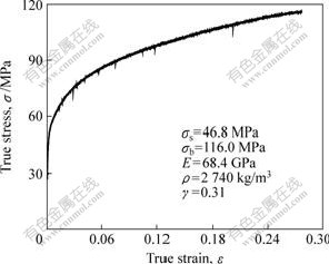
Fig.2 True stress��true strain curve of AA3003-O
Only moderate deformations are usually desirable because of the limitation imposed by the plastic buckling in the electromagnetic tube compression. So, the discharge voltage values in the experiments and optimization analysis are not high enough to make the plastic buckling of tube in this work.
2.2 Basic experimental results with coil C1
The radial displacement of deformed tube (100 mm long) with coil C1 is shown in Fig.3. It can be seen that an increase of discharge voltage enhances the absolute value of radial displacement. The radial deformation along axial direction of the tube is nonuniform and the maximum deformation appears at the center of outer generatrix of tube wall, which is indicated by ��tube center�� as illustrated in Fig.3 for the starting point of radial displacement measurement.
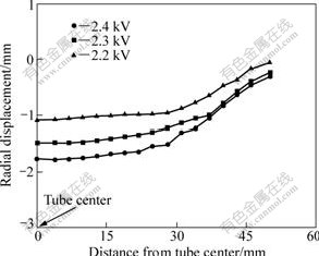
Fig.3 Influence of discharge voltage on radial displacement
Coil C1 and 50, 60, 80 and 100 mm-long tubes were chosen in tube compression experiments under the discharge voltage of 2.2 kV. Therefore, the length ratio of tube to coil, R, was 50/100, 60/100, 80/100 and 100/100 correspondingly. As shown in Fig.4, when the discharge energy (voltage) held constant and R is not greater than 0.8, the distinct deflection of the magnetic field, which takes place at the both ends of forming system, causes the larger radial displacement at tube ends, the narrower region of uniform deformation and drum-like final tube shape. With decreasing R, the deformation gradient increases sharply from tube centre to end. Whereas, when R is not less than 1, the larger radial deformation takes place at tube centre and the deformed tube shows horn shape. Therefore, when R is greater than 0.8 and less than 1, there could be a critical ratio, Rc, which corresponds to the homogeneous radial deformation.
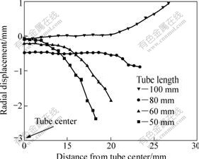
Fig.4 Effect of tube length on radial displacement (R��1)
3 Design optimization model of EMF based on FEM
3.1 FEM model
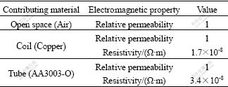
Only half view of an electromagnetic model is considered in FEM model because of symmetry, as shown in Fig.1. An electromagnetic model and a mechanical model are established, respectively. The electromagnetic model consists of far field air region, near field air region, tube and coil, which are coaxial and concentric. The electromagnetic properties of contributing materials are included in Table 2. Ref.[14] presented the following hypotheses for the electromagnetic field numerical simulation of EMF: the coil current is distributed uniformly on the cross section of coil turn; the permeability and electric conductivity of materials are constant and isotropic; and the displacement current is neglected. The finite element meshes and boundary conditions for the electromagnetic model and the elements attributes are the same as Refs.[10, 15], where the dynamic deformation of electromagnetic tube compression was performed.
Table 2 Material parameters of electromagnetic model
The mechanical model, only related to the tube and coil, and its mesh division are duplicated from electromagnetic model. The quasi-static stress��strain data are scaled, to adapt the high strain-rate conditions of the process, by means of the Cowper-Symonds constitutive model[3]:
![]() (2)
(2)
where ��y is the quasi-static flow stress (seen in Fig.2); ![]() is the strain rate; and P=6 500 s-1 and m=0.25 are specific parameters for aluminium alloy.
is the strain rate; and P=6 500 s-1 and m=0.25 are specific parameters for aluminium alloy.
The numerical simulation for the electromagnetic tube compression has been performed by using FEM software ANSYS based on the models and boundary conditions mentioned above. The magnetic forces can be easily transferred from the electromagnetic model into the mechanical model and applied to nodes with relative boundary conditions. And the inertial effects are considered in the mechanical analysis. The total simulation time is 200 ��s and the time step is 5 ��s. A good agreement between the predicted and the experimental data is obtained, where the relative error of the largest radial displacement is 6.18% at voltage of 2.4 kV[15]. So, the precision of numerical simulation result is quite reasonable and considerable, which can be used in the optimization analysis of EMF process.
3.2 Design optimization model
3.2.1 Basic equations
Design optimization is a technique to determine an optimum design which meets all specified requirements but with a minimum expense of certain factors such as mass, surface area, volume, and stress. In other words, the optimum design is usually the one as effective as possible[12].
Actually, any ANSYS item that can be expressed in terms of parameters can be subjected to design optimization. The design optimization, based on the finite element analysis with some items expressed in terms of parameters, includes three kinds of scalar factors: design variables, state variables and objective function.
The design variables are the independent quantities that are varied to achieve the optimum design. Their formats are
x=[x1, x2, x3, ��, xn] (3)
where n is the number of design variables. The upper and lower limits of n are specified to serve as constraints on the design variables. These limits define the range of variation of the design variables:
xi��xi��![]() (i=1, 2, 3, ��, n) (4)
(i=1, 2, 3, ��, n) (4)
The state variables are known as dependent variables and are typical response quantities that are functions of the design variables. Therefore, the typical function for the design optimization is
f=f(x) (5)
It is subject to the following constrains:
wi��wi(x)��![]() (i=1, 2, 3, ��, m) (6)
(i=1, 2, 3, ��, m) (6)
where f is objective function; wi is the state variable that constraints the design, and the overline and the underline show the upper and lower boundaries, respectively; and m is number of the state variables.
A design that satisfies all specified constraints (those on the state variables as well as on the design variables) is known as the feasible design. The best design is the one which satisfies all constraints and produces the minimum objective function value. If all design sets are infeasible, the best design set is the one closest to being feasible, irrespective of its objective function value.
The first order method is chosen for the analysis of the homogeneous radial deformation in electromagnetic tube compression, which is based on design sensitivities and is suitable for problems that require high accuracy. For this method, the program performs a series of analysis-evaluation-modification cycles and its process is repeated until all specified criteria are met.
3.2.2 Design optimization model of homogeneous radial deformation
The sketch map of design optimization process of homogeneous radial deformation during electromagnetic tube forming is shown in Fig.5. Firstly, referring to Fig.1 and Fig.4, the half tube length, WH, is chosen to serve as the design variable in pre-processor of the sequential coupling numerical simulation of electromagnetic tube compression. For the simplicity, the small variation of system inductance is neglected. Then, the parametric model mentioned above is solved when a specific half tube length value is assigned to WH. The initial value of WH and its upper and lower limits are assigned to 50 mm, 60 mm and 30 mm, respectively. And the discharge voltage is 2.25 kV and is held constant during the design optimization process.
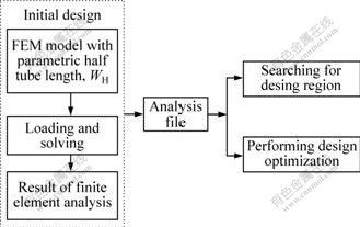
Fig.5 Sketch map of half tube length prediction
In the postprocessor, the radial displacement of the center node on the outer generatrix is chosen to serve as the benchmark node, as seen in Fig.6, based on the definition of ��tube center��. The state variable is specified by the absolute value of the difference of radial displacement between other nodes and the benchmark one, whose upper limit is 0.2 mm. Volume of the axisymmetric model of tube pertinent to WH, VT, is proposed to serve as the objective function (OBJ). In common, the upper limit is 1% of OBJ. In order to improve the design accuracy, the upper limit is set to 0.1 mm3 corresponding to the initial tube volume of 30 164.7 mm3. Lastly, the design optimization is started by the first order method.
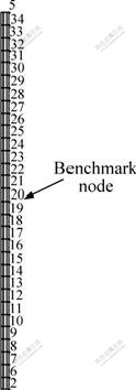
Fig.6 Node number along outer generatrix of tube
4 Results and discussion
A total of 11 design sets were performed. As soon as the first order method is concerned, one design set includes many times calculating loops. In this optimization analysis, only the eleventh one is the feasible design set. The radial displacement of the ��optimized length�� tube is shown in Fig.7, where it is compared with the radial deformation of initial tube. In consideration of the relativity of the optimized result, the technique of setup and selection of optimization methods of three factors, and the complexity of space-time distribution of magnetic force, the radial deformation of the optimized tube length is relatively homogeneous. The optimized tube length is 92.44 mm, whose average deformation is larger than that of the initial tube.
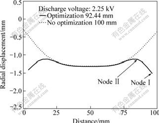
Fig.7 Effect of optimum tube length on radial deformation
The effects of discharge voltage on the homogeneous radial deformation is presented in Fig. 8, where the increasing discharge voltage makes for larger but worse homogeneous radial deformation, with more marked ��humps�� presenting in vicinity of both tube ends without changing tube length. This is because the length ratio, R, determines the distribution of magnetic force acting on tube and then governs its deformation. And discharge voltage only decides the peak value of magnetic force acting on the tube. So, the critical ratio, Rc, is insensitive to the discharge voltage.
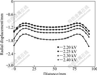
Fig.8 Effect of discharge voltage on deformation uniformity
In order to find more accurate tube length corresponding to the homogeneous radial deformation, the tubes with length deviation of ��0.04 mm are chosen and their lengths are 91.0, 92.0, 93.0 and 94.0 mm, respectively. The discharge voltage is 2.25 kV. Fig. 9 shows the experimental results. When the tube length is less than or equal to 92.0 mm, the larger deformation occurs in the middle of the tube; whereas, when the tube length is larger than 93.0 mm, the larger deformation occurs at tube end. Therefore, the tube length relative to the uniform radial deformation is between 92.0 and 93.0 mm. All the experimental and the calculated results indicate that the uniform radial deformation along the axial direction exists in practice. So, Rc is between 0.92 and 0.93 in the forming system presented in this work.
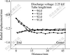
Fig.9 Radial displacement of test tube
According to the testing results above, the tendency of tube compression under magnetic force can be denoted
by the relative displacement (dt/dc), the ratio of the radial displacement at tube end (dt) to that at tube center (dc). According to the experimental results, the relationship between R and dt/dc is included in Fig.10, where dt/dc=1 corresponds to the homogeneous radial deformation along the axial direction and R=Rc. Therefore, the tendency of tube compression can be divided into three kinds of conditions as follows.
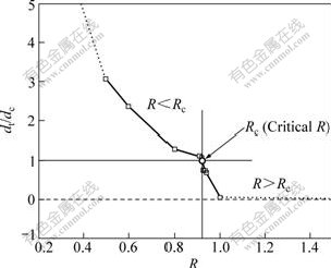
Fig.10 Effects of R on relative deformation
1) R��Rc: it corresponds to dt/dc��1 and the final tube presents horn shape; the value of dt/dc decreases with increasing R; and the local tube compression contributes to inside bead forming.
2) R=Rc: it corresponds to dt/dc=1 and the radial displacement is relatively uniform along the axial direction.
3) R��Rc: it corresponds to dt/dc��1 and the final tube presents drum shape; the value of dt/dc increases with decreasing R; and it contributes to necking.
By the combination of the experimental and optimization analysis results using coils C0, C1, C2 and C3, the comparison of investigating results of coils with varying length is concluded in Fig.11, where the testing results have upper and lower limits and the corresponding optimization result is a constant value. It can be seen that, for it makes for larger mutual inductance between the coil and tube, the longer coil improves the magnetic field shielding of EMF system, reduces the ��end effect�� and improves Rc value. Namely, Rc improves with increasing coil length (lc) and could approach to 1, for example, the Rc value relative to lc=250 mm at the right side of Fig.11. Inversely, it could approach to 0, when lc=20 mm, at the left side of Fig.11. Furthermore, the optimizing value of Rc with coils C0 and C1 is between the upper and lower limit of testing values; and those with coil C2 and C3 are larger than their upper limits. The difference between the FEM model and the experimental terms may be the main reason for the investigating results above.

Fig.11 Relation between Rc and lc
According to the principle of EMF of metal tube, the smaller gap between coil and tube contributes to the greater magnetic field and magnetic force and the weaker ��end effect��. Therefore, for a given tube, decreasing inner diameter of coil means reducing gap between coil and tube, which improves the corresponding Rc of varied coil length. Inversely, the larger gap could result in the reducing of Rc.
5 Conclusions
1) The design optimization model of homogeneous radial deformation is established based on the combination of the design optimization and the sequential coupling numerical simulation.
2) During the electromagnetic tube compression, the distribution of homogeneous radial deformation is relative and there are two ��humps�� presenting in vicinity of tube ends. The tube length corresponding to the homogeneous radial deformation is insensitive to discharge voltage.
3) The deformation tendency of tube compression depends on the length ratio of tube to coil, R, which has a critical value, Rc, corresponding to the radial uniform deformation along the axial direction. When R��Rc, the final tube presents horn shape and the shorter coil makes for the local deformation. If R��Rc, the final tube presents drum shape and the longer coil makes for larger deformation at tube ends and the greater distribution gradient of radial deformation.
4) Rc increases with the coil length and could approach to 1; inversely, it could approach to 0.
References
[1] JABLONSKI J, WINKLER R. Analysis of the electromagnetic forming process [J]. Int J Mech Sci, 1978, 20: 315-325.
[2] VOHNOUT V J. A hybrid quasi-static/dynamic process for forming large metal parts from aluminum [D]. Ohio, Columbus: Ohio State University, 1998: 1-15.
[3] MAMALIS A G, MANOLAKOS D E, KLADAS A G, KOUMOUTSOS A K. Electromagnetic forming and powder processing: Trends and developments [J]. Appl Mech Rev (ASME), 2004, 57(4): 299-324.
[4] WANG L F, CHEN Z Y, LI C X, HUANG S Y. Numerical simulation of the electromagnetic sheet metal bulging process [J]. International Journal of Advanced Manufacturing Technology, 2006, 30: 395-400.
[5] EL-AZAB A, GARNICH M, KAPOOR A. Modeling of the electromagnetic forming of sheet metals: State-of-the-art and future needs [J]. Journal of Materials Processing Technology, 2003, 142: 744-754.
[6] LI Zhong, LI Chun-feng, YU Hai-ping, ZHAO Zhi-heng. Effect of tube size on electromagnetic tube bulging [J]. Transactions of Nonferrous Metals Society of China, 2007, 17(4): 705-710.
[7] IMBERT J M, WINKLER S L, WORSWICK M J, OLIVEIRA D A, GOLOVASHCHENKO S. The effect of tool-sheet interaction on damage evolution in electromagnetic forming of aluminum alloy sheet [J]. Journal of Engineering Materials and Technology, 2005, 27(1): 145-153.
[8] MAMALIS A G, MANOLAKOS D E, KLADAS A G, KOUMOUTSOS A K. Electromagnetic forming tools and processing conditions: Numerical simulation [J]. Materials and Manufacturing Processes, 2006, 21: 411-423.
[9] UNGER J, STIEMER M, SVENDSEN B, BLUM H. Multifield modeling of electromagnetic metal forming processes [J]. Journal of Materials Processing Technology, 2006, 177: 270-273.
[10] YU H P, LI C F, DENG J H. Sequential coupling simulation for electromagnetic-mechanical tube compression by finite element analysis [J]. Journal of Materials Processing Technology, 2009, 209(2): 707-713.
[11] YU Hai-ping. Buckling criterion and deformation analysis of electromagnetic tube compression [D]. Harbin: Harbin Institute of Technology, 2006: 70-71. (in Chinese)
[12] LU Xian-feng. Application basis for the optimum design [M]. Shanghai: Tongji University Press, 2003: 1-20. (in Chinese).
[13] YU H P, LI C F, DENG J H. Forecast of discharge voltage for electromagnetic tube forming based on FEM analysis [J]. Materials Science Forum, 2008, 575/578: 192-197.
[14] LEE S H, LEE D N. A finite element analysis of electromagnetic forming for tube expansion [J]. Journal of Engineering Materials and Technology, 1994, 16: 250-254.
[15] YU Hai-ping, LI Chun-feng. Study of coil length on tube compression in electromagnetic forming [J]. Transactions of Nonferrous Metals Society of China, 2007, 17(6): 1270-1275.
Foundation item: Projects(50575052, 50805036) supported by the National Natural Science Foundation of China
Corresponding author: YU Hai-ping; Tel: +86-451-86413970; E-mail: haipingy@hit.edu.cn
DOI: 10.1016/S1003-6326(09)60089-3
(Edited by YANG Bing)
