
J. Cent. South Univ. (2016) 23: 1264-1272
DOI: 10.1007/s11771-016-0376-5

Effects of fundamental factors on coupled vibration of wind-rail vehicle-bridge system for long-span cable-stayed bridge
ZHANG Ming-jin(������), LI Yong-le(������), WANG Bin(����)
Department of Bridge Engineering, Southwest Jiaotong University, Chengdu 610031, China
 Central South University Press and Springer-Verlag Berlin Heidelberg 2016
Abstract:
In a wind-vehicle-bridge (WVB) system, there are various interactions among wind, vehicle and bridge. The mechanism for coupling vibration of wind-vehicle-bridge systems is explored to demonstrate the effects of fundamental factors, such as mean wind, fluctuating wind, buffeting, rail irregularities, light rail vehicle vibration and bridge stiffness. A long cable-stayed bridge which carries light rail traffic is regarded as a numerical example. Firstly, a finite element model is built for the long cable-stayed bridge. The deck can generally be idealized as three-dimensional spine beam while cables are modeled as truss elements. Vehicles are modeled as mass-spring-damper systems. Rail irregularities and wind fluctuation are simulated in time domain by spectrum representation method. Then, aerodynamic loads on vehicle and bridge deck are measured by section model wind tunnel tests. Eight vertical and torsional flutter derivatives of bridge deck are identified by weighting ensemble least-square method. Finally, dynamic responses of the WVB system are analyzed in a series of cases. The results show that the accelerations of the vehicle are excited by the fluctuating wind and the track irregularity to a great extent. The transverse forces of wheel axles mainly depend on the track irregularity. The displacements of the bridge are predominantly determined by the mean wind and restricted by its stiffness. And the accelerations of the bridge are enlarged after adding the fluctuating wind.
Key words:
wind-vehicle-bridge system; coupled vibration; long-span cable-stayed bridge; fundamental factors��
1 Introduction
To catch up the economic development, rapid and efficient transportation systems are required for the society. As a result, more long span bridges have been built throughout the world. Due to the flexibility of the long-span bridges and the moving feature of vehicles, the coupled vibration between the moving vehicles and the long span bridges is intense and has been focused on continuously in the past [1-5]. For the coupled vehicle-bridge system, random track irregularity/road roughness is regarded as a major source of excitation. And the vibration of moving vehicles leads to the forced vibration of the bridge. In return, the distortions of the bridge deck change the traveling bound surface of the vehicles and further influence the dynamic behaviors of the vehicles.
Furthermore, the dynamic behaviors of the vehicle and bridge may turn to more serious when the vehicle- bridge system is subjected to crosswind. Under crosswind, both the bridge and the vehicle have to be forced with wind loads. With the motion of the vehicle, the aerodynamic forces of the bridge deck alter along its length direction with the location of the vehicle. a complicated wind-vehicle-bridge (WVB) system is formed as the vehicle moving on the bridges under crosswind [6]. Xu and Guo [7] presented a dynamic analysis framework for the coupled road vehicle and cable-stayed bridge under turbulent winds. Xu et al [8] also presented an analysis framework for a suspension bridge under high wind and running train, in which the train runs inside the box of the bridge and no wind loads act on the train. Cai and Chen [9] presented a analytical process for road vehicle-bridge system under crosswind. Chen and Cai [10] proposed the road vehicle accident model on long-span bridges in windy environments based on the coupled dynamic solution of WVB system. Xu and Guo [11] analyzed the ride comfort of road vehicles running on a long-span cable-supported bridge under crosswind. They showed that the ride comfort in the lateral direction is influenced by the crosswind and that in the vertical direction is affected by the motion of the bridge. Li et al [6] used a composite section model to test the aerodynamic forces on both train and bridge deck in the vehicle-bridge system, and formed a dynamic model for WVB system in the time domain. Guo and Xu [12] obtained the accident road vehicle speeds as the vehicles run on a long-span cable-stayed bridge in fluctuating winds. Kwon et al [13] studied the vibration and ride quality of a maglev vehicle moving on a guideway suspension bridge in turbulent wind. They showed that the vehicle speed and wind forces affect the motion of the vehicle sensitively. Xia et al [14] applied the dynamic model of a wind-train-bridge system to decide the allowed vehicle speed. Chen et al [15] computed the dynamic stress of a long-suspension bridge under both wind and vehicle loads. The results showed that running train plays a predominant role in the stress responses of the bridge compared with the wind and the road vehicle loads. Li et al [16] investigated the vibration characteristics of the WVB system during two trains meeting each other on a large span bridge. It was shown that the meeting processes of two trains are control factors for the system.
The above studies about the system focused on the analysis frame and the responses. Actually, the WVB system is very complicated and accompanied with many fundamental factors, such as the stochastic wind, the rail/road regulations, the vibrations of vehicles, and the stiffness of bridges. The effects of these factors on the responses of the vehicles and bridges, which are significant reference information for the designers and traffic management departments to make right decisions, have not been explored systemically. This work, therefore, focuses on the analysis of the effects of these fundamental factors. A dynamic model for the WVB system is first introduced considering the wind, vehicle, bridge and the interactions among them. After taking a long-span cable-stayed bridge and a light rail vehicle as the applied objects, the effects of the fundamental factors are revealed in a systematical way.
2 Dynamic model of WVB system
In a WVB system, wind, vehicle, and bridge are the basic components. There are timely interactions among these components. The dynamic model for each of them and their interactions are introduced in the following contexts.
2.1 Wind
Wind, in terms of its velocity, is a random process and usually regarded as a stationary Gaussian stochastic process. For a long-span bridge, a wind velocity field is required to cover the total length of the deck and the total height of the pylons. Since the dimensions of long-span bridges are great, the velocity histories on huge numbers of space points have to be generated, which will lead to a high computational work by the typical spectral representation method [17]. Li et al [18] simplified the generation of the stochastic wind velocity field around a long-span bridge. The wind velocity field is composed of many one-dimensional independent wind fields along pylons and deck, respectively.
2.2 Vehicle
A light rail vehicle will be studied in the latter analysis. The rail vehicle consists of several locomotives and coaches. All the locomotives and coaches can be modeled as mass-spring-damper systems. The main parts are taken as ideal rigid bodies, and they are connected with each other through springs and dampers. A 4-axle vehicle model for a locomotive or coach is shown in Fig. 1. It is composed of seven rigid bodies: one vehicle body, two bogies and four wheelsets.
It is supposed that the vehicle moves at a constant speed along a straight line without derailment. In this regard, the degree of freedom (DOF) of each rigid body along the traveling direction of the vehicle is neglected. Thus, each vehicle body and bogie are specified with five DOFs with translation in the lateral and vertical directions and angular motions including rolling, yawing and nodding. A wheelset just has two DOFs for its lateral and yawing motions. Based on the two DOFs, the other motion status of the wheelset can be determined by the wheel-rail contact geometry. In all, the four-axle vehicle model has 23 DOFs in total to represent its dynamic characteristics. Because the DOF of each vehicle in the vehicle movement direction is omitted, the motion of a locomotive or coach is independent on the other. The equations of motion of the vehicle body and bogies can be directly derived using the D��Alembert��s principle. Based on the Kaller��s creep theory for the wheel-rail contact, the equations of motion of wheelsets can also be obtained [19]. The equations of motion of the vehicle system are expressed as follows:
 (1)
(1)
where uv is the vector of vehicle displacement in each DOF; Mv, Cv, Kv are the mass matrix, damping matrix and stiffness matrix of the vehicle, respectively; Fstv and Fbuv are the static wind load and buffeting loads acting on the vehicle, respectively; and Fbv is the wheel-rail interactions which are induced by track irregularity and deck motion.
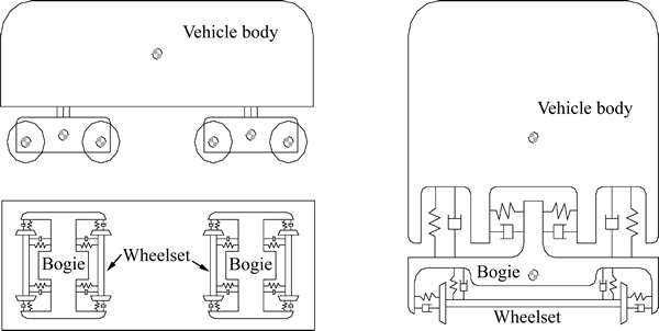
Fig. 1 Mass-spring-damper model for locomotive or coach
2.3 Long-span bridge
As a common, the analytical model of a long-span bridge can be established using the finite element method. In this model, deck is idealized as a three-dimensional spine beam while cables and steel trusses are idealized as truss elements. Pylons and pies also are regarded as beam elements. The truss elements with rigid arms are occasionally used to reduce the total DOFs of the model of the long-span bridge. The final equations of motion of the whole bridge are written as
 (2)
(2)
where ub is the vector of the bridge displacement; Mb, Cb and Kb are the mass matrix, damping matrix and stiffness matrix of the bridge, respectively; Fstb, Fbub and Fseb are the static wind load, buffeting load and self-excited load acting on the bridge, respectively; and Fvb is the wheel-rail interaction force vector which is exerted on the deck by the vehicle through wheel-rail contact points. The structural damping Cb is assumed to be Rayleigh damping expressed by
 (3)
(3)
where the damping constants �� and �� are determined by two specific frequencies with the corresponding structural damping ratios.
2.4 Interaction between wind and bridge
Wind loads on a bridge can be classified into three parts: static wind loads, buffeting loads and self-excited loads. For a long-span bridge, the shape of pylons is usually bluff and the size along the main wind flow is small. Therefore, the aeroelastic coupling effects between the pylons and wind are very weak and the resulted self-excited loads on the pylons can be omitted. For most cable-stayed bridges, it is known that the vibration of cables will exert little influence on the vibration of the whole bridge. Therefore, only static loads are considered for cables in the model.
2.4.1 Static wind loads
Static wind loads are induced by the mean part of wind. For line-like structure, static wind loads are usually expressed by three components: drag, lift and moment as follows [20]:
 (4a)
(4a)
 (4b)
(4b)
 (4c)
(4c)
where �� is the air density; U is the mean wind speed; B is the width of body along the mean wind; H is the cross-wind projected area (per unit length ) normal to the mean wind direction; CD, CL and CM are the drag, lift and moment coefficients, respectively.
Static wind loads acting on a deck segment will vary with the motion of the vehicle along the bridge deck. When the vehicle moves on a certain deck segment, the aerodynamic effects of the vehicle should be taken into account in the determination of aerodynamic coefficients of the deck segment. The existence of the vehicle on the deck will alter the ambient flow above the deck to a great extent and the aerodynamic forces on the deck are correspondingly changed compared with that without the vehicle. Similarly, the aerodynamic loads on the vehicle are also affected by the geometrical shape of the deck section. Considering the line-like configuration of both bridge deck and long train, the section model test in wind tunnel can be utilized to obtain their aerodynamic parameters. When no vehicle is on deck, the aerodynamic coefficients of the deck can be easily obtained by routine section model test. In order to measure the respective aerodynamic coefficients of the deck and vehicle when the vehicle is on the deck, a simple but effective device named the cross slot system [21] is used to separate the wind loads on the bridge deck and the vehicles from each other. In this modeling, when the vehicle moves on a deck segment, the aerodynamic coefficients considering the aerodynamic effects of the vehicle are selected for computing the wind loads on the deck segment.
2.4.2 Buffeting loads
Buffeting loads are induced by the fluctuation of stochastic wind. According to the quasi-steady theory, buffeting loads on the deck and pylon can be expressed as follows [22]:
 (5)
(5)
where  and
and  are the slopes of CL and CM respectively; ��i (i=1,2��5) is the aerodynamic admittance functions; u(t) is the fluctuating wind velocity component in the direction of mean wind; w(t) is the fluctuating wind velocity component in the vertical direction for deck or in the spanwise direction for pylons; u(t) and w(t) can be simulated by the simplified spectral representation method discussed in Section 2.1. The values of CD, CL, CM, and depend on whether vehicles move on the deck or not and they can be determined with reference to the static wind loads (Section 2.4.1).
2.4.3 Self-excited loads
Self-excited loads, expressed as the functions of the displacement and velocity of the bridge deck, reflect the aeroelastic interactions between the wind and deck. Scanlan and JONES [22] firstly presented the expressions of the self-excited loads with the flutter derivatives of the deck in the frequency domain. In the time domain, models of self-excited loads include two forms: 1) the form of indicial functions; and 2) the form of convolution integrals. It considered that the self-excited loads are generated by a linear mechanism. The self-excited loads can be expressed in terms of convolution integrals between the deck motion and the impulse response function. For example, the self-excited moment Mse(t) can be expressed as


 (6)
(6)
where Mp, Mh and M�� are the lateral, vertical and torsional movements of the bridge deck, respectively; and fij (i=M; j=p, h, a) are the response functions of unit impulse displacement j. the impulse response functions can be expressed as

 (7)
(7)
2.5 Interaction between wind and vehicle
Similarly to the wind loads on the bridge, wind loads on vehicles are also theoretically decomposed as three parts: static wind loads, buffeting loads and self-excited loads. Since the width of the target light rail vehicle is only about 3 m and the maximum wind speed beyond which the vehicle should be stopped is not very high, the aeroelastic stiffness and the aeroelastic damping of vehicles are therefore limited. As a result, the self- excited loads on the vehicle can be omitted. The aerodynamic effects of the ambient flow of the deck on the wind loads of the vehicle are considered during the determination of vehicle aerodynamic coefficients using the cross slot system in Section 2.4.1. In the calculation of buffeting loads on the vehicle, the fluctuating wind velocity on the vehicle is identical to that on the deck segment where the vehicles are located.
2.6 Interaction between vehicle and bridge
The geometrical contacts and interaction forces are two aspects in the relation between the vehicle and the bridge. The motion of the vehicle is restricted by the bridge deck on which the rails are fixed, namely. the bridge provides the boundary condition for vehicles. Therefore, the motion of the vehicle is influenced by the deck displacement, especially by the vibration of the deck. Without the derailment, the displacements of both the vehicle and the bridge deck are identical in the vertical direction at the wheel-rail contact points. There are lateral, longitudinal and spin creeps between vehicle wheels and the rails. The deck displacements and the actual track irregularities can be combined as equivalent track irregularities which are regarded as excitation sources to the vehicle system. In the vehicle-bridge interaction, the vehicle exerts its action on the bridge mainly through the wheel-rail interaction forces. At the wheel-rail contact point, the wheel-rail forces acting on the deck are equal and opposite of those acting on the vehicle.
3 System assembling and solution
During the passage of the vehicle across the long- span bridge, the vehicle excites the bridge mainly through the wheel-rail interaction forces while the bridge excites the vehicle mainly with the movement of the deck. Thus, the bridge and the vehicle can be regarded as two subsystems and coupled through the wheel-rail interaction forces and geometric contact. The equations of motion of the WVB system can be assembled in the following equation:

 (8)
(8)
where the subscripts b and v indicate the bridge and the vehicle subsystems, respectively. The two subsystems can be solved independently. According to the relations between the two subsystems, an iterative process is applied to ensuring the displacement and force compatibility conditions to be satisfied at the wheel-rail contact points at each time step. The iterative solution can be established for both the vehicle-bridge relation and self-excited forces of the deck as follows:
1) Combine the track irregularities and deck movements at the last time step to yield the equivalent track irregularities at the current time step.
2) Calculate the forces acting on the vehicle induced by the equivalent track irregularities and wind.
3) Solve the vehicle subsystem dynamic equation in Eq. (7) independently with the Newmark integration method to obtain the initial vehicle responses.
4) Solve the bridge responses.
5) Repeat interaction from Steps 1) to 4) after updating the deck displacement with the results in Step 4) until the geometric and force compatibility conditions at the wheel-rail contact points are satisfied well and then continue the next time step from Steps 1) to 5).
4 Numerical analysis of fundamental factor effect
4.1 System description
Shanghai-Chongming channel, which is located in the eastern part of Shanghai with a total length about 25.5 km, is the longest bridge-tunnel engineering in the world until now. Yangze River Bridge is a key node in the channel. Two-lane urban light rail vehicles are set and the design speed is about 90 km/h. Yangze River Bridge is a twin pylons cable-stayed bridge across Yangze River. Its overall length is 1430 m with two main spans of 730 m length and two pylons of 209 m height (Fig. 2). Its girder is a steel box with a width of 51.5 m and a height of 5 m as shown in Fig. 3.
The fundamental frequencies of the bridge in the vertical, lateral and torsional directions are 0.2253, 0.2922 and 0.7062 Hz, respectively. The light rail vehicle contains two locomotives at the ends and 8 coaches in the middle. The design wind speed of this bridge is 49.8 m/s at the deck level and the mean wind velocity profile which is used in the simulation of the wind speed field is expressed as
 (9)
(9)
where  is the mean wind velocity at the height of Z;
  is the design wind velocity at the deck height of Zd; ��(=0.12) is the dimensionless power exponent related to the ground surface roughness.
In order to reveal the effects of fundamental factors in the coupled vibration of WVB system, the fundamental factors are listed in Table 1. The mean wind velocity and vehicle moving speed are 30 m/s and 90 km/h, respectively.
4.2 Effect of wind condition
Different type of wind conditions lead to different static and dynamic behaviors of the vehicle and the bridge. The transverse displacement histories in the middle span of bridge under no wind (Case 1) and mean wind (Case 2) acting on the bridge when vehicles move across the bridge are plotted in Fig. 4. The transverse displacement of the bridge increases obviously in the mean wind condition. Table 2 lists the maximum dynamic response of the vehicle and the bridge for different cases. Compared with no wind action, the safety factor of overturning, wheel axle��s transverse force, wheel weight decrement rate of load, derail factor for locomotives and coaches are enlarged in the mean wind condition. Additional to the transverse responses, the mean wind also brings out the vertical wind loads and is responsible for the vertical displacement increment of the bridge. Due to the steady feature of mean wind, all the maximum accelerations are rarely changed compared with no action of wind.
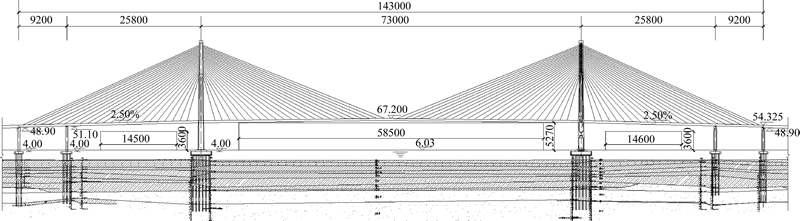
Fig. 2 Yangze River Bridge in Shanghai-Chongming channel (Unit: cm)
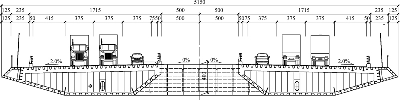
Fig. 3 Cross section of bridge deck (Unit: cm)
Table 1 Numerical analysis with various fundamental factors
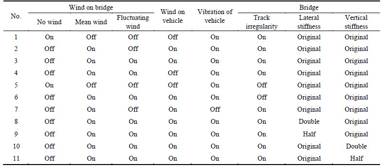
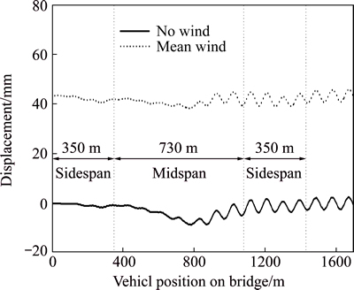
Fig. 4 Transverse displacement histories in middle span of bridge
The natural wind (mean wind with fluctuating wind) acting on the bridge is considered in Case 3. Figure 5 shows the vertical acceleration histories of the 8th coach under the mean wind and the natural wind. It can be seen that the fluctuating wind in the natural wind worsens the vertical acceleration of the vehicle to some extent. From Table 2, the fluctuating wind alters the acceleration responses dramatically, especially for the bridge, which is the result of the dynamic nature of the fluctuating wind.
4.3 Effect of bridge buffeting
Fluctuating wind causes bridge buffeting and further affects the states of the vehicle. In Case 4, the wind loads on the vehicle are ignored to show the effect of the bridge buffeting on the responses. Compared with Case 1, the maximum vertical acceleration of the vehicle grows from 1.503 m/s2 to 1.998 m/s2 (See Table 2). The growth rate of the vehicle is 32.9%. According to the analysis in 4.2, mean wind has live influence on the change of the maximum accelerations. Therefore, the bridge buffeting causes large increase of the vertical acceleration of the vehicle.
4.4 Effect of track irregularity
Rail irregularities are the main excitations of vehicle vibration. The vehicle-bridge interaction depends on rail irregularities to great extent. The Yangze River Bridge is on an urban light railway whose vehicle design velocity is 90 km/h and thus American six-rail irregularity spectra for medium speed railway are adopted. To obtain the effect of track irregularity, the track with no irregularities without and with wind is considered in cases 5 and 6. The wheel axle transverse force histories in various track irregularities conditions are shown in Fig. 6. Compared with cases 1 and 3, the effect of track irregularities on the system is also revealed as shown in Table 2. No matter there is wind or not, the track irregularities extraordinarily shift the vehicle accelerations and wheel axle transverse forces.
Table 2 Maximum dynamic responses for cases 1 to 11
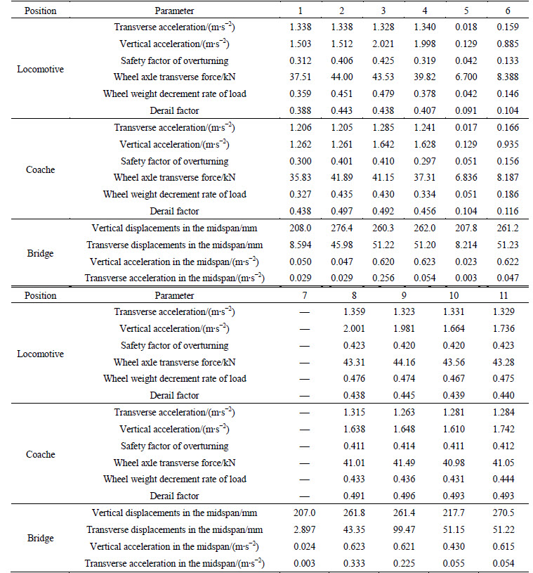
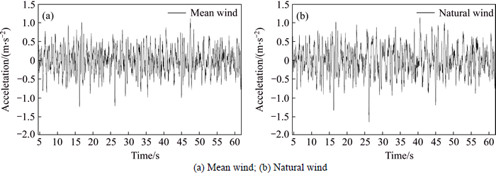
Fig. 5 Vertical acceleration histories of vehicle:
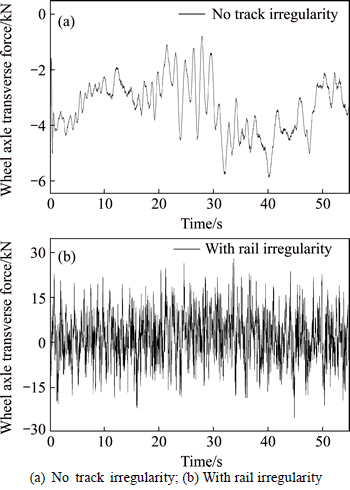
Fig. 6 Transverse force histories of wheel axle:
4.5 Effect of vehicle vibration
In Case 7, the analysis does not contain the vibration of the vehicle. The vehicle is replaced by a series of moving mass. Table 2 shows the maximum responses when not considering the vehicle vibration. The vehicle mass is relative small compared with the mass of the bridge, so the vibration of the vehicle is not large enough to excite the violent oscillatory motions of the bridge.
4.6 Effect of bridge stiffness
Figure 7 shows the transverse displacement responses in the middle span of bridge with various stiffness of the bridge in the lateral direction (cases 8 to 11). From the results listed in Table 2, the maximum vertical accelerations of the vehicle are affected by the bridge stiffness slightly. The diversity of the bridge stiffness is mainly contributed to the different responses of the bridge itself, including the displacements and accelerations. Larger stiffness leads to lower displacements and larger acceleration in the corresponding direction.
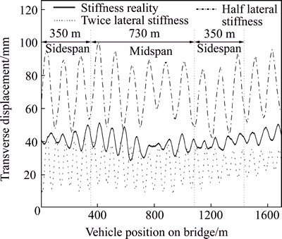
Fig. 7 Transverse displacement with various bridge stiffness
5 Conclusions
1) The accelerations of the vehicle depend on the fluctuating wind and the track irregularity greatly. The buffeting of the bridge affects the accelerations of the vehicle through the contact between the vehicle and the bridge. The bridge stiffness has few effects on the accelerations of the vehicle.
2) The transverse forces of wheel axles mainly depend on the track irregularities. They vary greatly with and without the track irregularity, but they are influenced hardly by the stiffness of the bridge.
3) The displacements of the bridge are predominantly determined by the mean wind. The fluctuating wind and the vehicle vibration affect the bridge displacements slightly.
4) On the whole, the accelerations of the bridge rise after adding the fluctuating wind. And the bridge stiffness influences the bridge accelerations to some extent.
References
[1] XIE Gui-hua, LIU Rong-gui, CAI Dong-sheng, CHEN Bei. Calculation model and mechanism analysis for rain-wind-induced vibration of stay cable [J]. Journal of Central South University, 2014, 21(3): 1107-1114.
[2] XIANG Huo-yue, LI Yong-le, CHEN Bo. Protection effect of railway wind barrier on running safety of train under cross winds [J]. Advances in Structural Engineering, 2014, 17(8): 1177-1187.
[3] ZHANG Zhi-tian, GE Yao-jun, ZHANG Wei-feng. Superposability of unsteady aerodynamic loads on bridge deck sections [J]. Journal of Central South University, 2013, 20(11): 3202-3215.
[4] LI Yong-le, HU Peng, CAI C S. Wind tunnel study of a sudden change of train wind loads due to the wind shielding effects of bridge towers and passing trains [J]. Journal of Engineering Mechanics, 2013, 139(9): 1249-1259.
[5] ZHAI Wan-ming, XIA He, CAI Cheng-biao. High-speed train-track-bridge dynamic interactions part I: theoretical model and numerical simulation [J]. International journal of Rail Transportation, 2013, 1(1/2): 3-24.
[6] LI Yong-le, QIANG Shi-zhong, LIAO Hai-li, XU You-lin. Dynamics of wind-rail vehicle-bridge systems [J]. Journal of wind engineering and industrial aerodynamics, 2005, 93(5): 483-507.
[7] XU You-lin, GUO W H. Dynamic analysis of coupled road vehicle and cable-stayed bridge systems under turbulent wind [J]. Engineering Structures, 2003, 25(4): 473-486.
[8] XU You-lin, XIA He, YAN Q S. Dynamic response of suspension bridge to high wind and running train [J]. Journal of bridge engineering, 2003, 8(1): 46-55.
[9] CAI C S, CHEN S R. Framework of vehicle-bridge-wind dynamic analysis [J]. Journal of wind engineering and industrial aerodynamics, 2004, 92(7): 579-607.
[10] CHEN S R, CAI C S. Accident assessment of vehicles on long-span bridges in windy environments [J]. Journal of wind engineering and industrial aerodynamics, 2004, 92(12): 991-1024.
[11] XU You-lin, GUO W H. Effects of bridge motion and crosswind on ride comfort of road vehicles [J]. Journal of wind engineering and industrial aerodynamics, 2004, 92(8): 641-662.
[12] GUO W H, XU You-lin. Safety analysis of moving road vehicles on a long bridge under crosswind [J]. Journal of engineering mechanics, 2006, 132(4): 438-446.
[13] KWON S D, LEE J S, MOON J W, KIM M Y. Dynamic interaction analysis of urban transit maglev vehicle and guideway suspension bridge subjected to gusty wind [J]. Engineering Structure, 2008, 30(12): 3445-3456.
[14] XIA H, GUO W W, ZHANG N, SUN G J, Dynamic analysis of a train-bridge system under wind action [J]. Computers and Structures, 2008, 86(19): 1845-1855.
[15] CHEN Zhi-wei, XU You-lin, LI Qi. Dynamic stress analysis of long suspension bridges under winds, railway, and highway loadings [J]. Journal of Bridge Engineering, 2011, 16(3): 383-391.
[16] LI Yong-le, XIANG Huo-yue, WANG Bin, XU You-lin. Dynamic analysis of wind-vehicle-bridge coupling system during the meeting of two trains [J]. Advances in structural engineering, 2013, 16(10): 1663-1670.
[17] DEODATIS G. Simulation of ergodic multivariate stochastic processes [J]. Journal of Engineering Mechanics, 1996, 8(4): 778-787.
[18] LI Yong-le, LIAO Hai-lin, QIANG Shi-zhong. Simplifying the simulation of stochastic wind velocity fields for long cable-stayed bridges [J]. Computers and Structures, 2004, 82(20/21): 1591-1598.
[19] GARG V K, DUKKIP R V. Dynamics of railway vehicle systems [M]. Canada: Academic Press, 1984.
[20] SIMIU P D, SCANLAN R H. Wind effects on structures [M]. 3rd ed. New York: John Wiley & Sons, 1996.
[21] LI Yong-le. Nonlinear three-dimensional coupling vibration of wind-vehicle-bridge systems [D]. Chengdu: Southwest Jiaotong University, 2003. (in Chinese)
[22] SCANLAN R H, JONES N P. Aeroelastic analysis of cable-stayed bridges [J]. Journal of Structural Engineering, 1990, 116(2): 279-297.
(Edited by YANG Hua)
Foundation item: Projects(U1334201, 51525804) supported by the National Natural Science Foundation of China; Project(15CXTD0005) supported by the Sichuan Province Youth Science and Technology Innovation Team, China
Received date: 2015-03-02; Accepted date: 2015-06-05
Corresponding author: LI Yong-le, Professor, PhD; Tel: +86-28-87601119; E-mail: lele@swjtu.edu.cn
Abstract: In a wind-vehicle-bridge (WVB) system, there are various interactions among wind, vehicle and bridge. The mechanism for coupling vibration of wind-vehicle-bridge systems is explored to demonstrate the effects of fundamental factors, such as mean wind, fluctuating wind, buffeting, rail irregularities, light rail vehicle vibration and bridge stiffness. A long cable-stayed bridge which carries light rail traffic is regarded as a numerical example. Firstly, a finite element model is built for the long cable-stayed bridge. The deck can generally be idealized as three-dimensional spine beam while cables are modeled as truss elements. Vehicles are modeled as mass-spring-damper systems. Rail irregularities and wind fluctuation are simulated in time domain by spectrum representation method. Then, aerodynamic loads on vehicle and bridge deck are measured by section model wind tunnel tests. Eight vertical and torsional flutter derivatives of bridge deck are identified by weighting ensemble least-square method. Finally, dynamic responses of the WVB system are analyzed in a series of cases. The results show that the accelerations of the vehicle are excited by the fluctuating wind and the track irregularity to a great extent. The transverse forces of wheel axles mainly depend on the track irregularity. The displacements of the bridge are predominantly determined by the mean wind and restricted by its stiffness. And the accelerations of the bridge are enlarged after adding the fluctuating wind.
