

Determination and application of stress-based forming limit diagram in
aluminum tube hydroforming
ZHOU Lin (����), XUE Ke-min (Ѧ����), LI Ping (��Ƽ)
School of Materials Science and Engineering, Hefei University of Technology, Hefei 230009, China
Received 15 July 2007; accepted 10 September 2007
Abstract:
The stress-based forming limit diagram(FLSD) established with limit stress is independent of the strain paths. Compared with traditional strain-based forming limit diagram(FLD), it is more convenient and practical to use as the criterion of forming limit under complex strain paths. The forming limit of 3A21 aluminum alloy sheet was tested and its forming limit diagram(FLD) was determined. Then the FLSD of 3A21 was constituted by transformation formulas between limit strain and limit stress. This FLSD was used in conjunction with LS-DYNA finite element simulations to predict the onset of fracture and limit forming pressure in tube hydroforming. The results indicate that the fracture often occurs in the transition region between corner and straight side of the tube, and the limit forming pressure is 46.4 MPa. The simulation result agrees with the experimental result, and the FLSD is able to predict the forming limit of tube hydroforming with remarkable accuracy.
Key words:
3A21 aluminum alloy; hydroforming; fracture; forming limit stress diagram; numerical simulation;
1 Introduction
Mass reduction is paramount in transportation applications such as automotive, railroad, and aerospace, because the mass of the final assembly has a direct impact on subsequent fuel consumption. In the past few years, the demand for mass reduction in modern vehicle construction has led to an increase in the application of hydroforming processes for the manufacture of automotive lightmass components made from steel or aluminum[1-2]. This trend results from the benefits offered by hydroforming compared with conventional manufacturing via stamping and welding, which consists in the possibility to form complex shaped components with integrated structures from single tubes[3]. Regarding existing variants of hydroforming processes a general distinction is to be drawn between forming of tubular material and forming of sheet material. Today, predominantly tubular material is considered for the mass production of hydroformed parts.
However, the prediction of forming limits in tube hydroforming(THF) is still a progressing field because of the complexity involved in the process[4]. It requires precise control of various forming conditions such as die
closing, internal pressure, end sealing and axial feeding in this process. The important modes of failure in this operation are bursting and wrinkling. Bursting takes place when pressure is applied without enough material feeding, while too much feeding of material tends to cause wrinkling.
Nevertheless, effective prediction and analytical method for the failure problems in THF has not been established up to the present, the failure analytical method used in sheet metal forming is inevitably applied in THF processes alternatively. The strain-based forming limit diagram(FLD) as an effective criterion of sheet forming quality has been extensively applied in THF research. In the latter work, it was noted that for steel, copper and aluminum alloy, the traditional strain-based flow limit curve(FLC) is a function of strain history[5-7]. Strain path effects undermine the utility of the traditional FLD for formability assessment of processes that are inherently non-linear, such as hydroforming of tubes. STOUGHTON[8] proposed a method through which, under a suitable set of constitutive assumptions, the strain-based FLC can be transferred to principal stress space. He has also shown that within the scope of the constitutive assumptions, there exists a single curve in principal stress space that represents the formability limit of the sheet. Therefore, the stress-based FLC appears to be attractive to predict the onset of necking when the sheet is subjected to nonlinear load paths. In this study, the stress-based forming limit diagram(FLSD) of 3A21 aluminum alloy sheet was constituted by transformation formulas between limit strain and limit stress. This FLSD was used in conjunction with LS-DYNA finite element simulations to predict the onset of fracture and limit forming pressure during hydroforming of tubes in square die.
2 Determination of FLSD
2.1 Determination of FLD
The FLD is based upon the work of KEELER [9] and GOODWIN[10] where the plane strain limit is given as follows:
FLD0![]() (1)
(1)
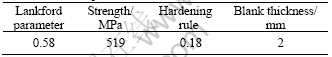
where n is the strain hardening coefficient, and n�� 0.21, t is the metal thickness in mm.
The key feature of the FLD is an experimentally determined forming limit curve(FLC). The shape and location of the FLC, which define the boundary between strain states that are always free of necks from those states that are prone to necking, are a characteristic of the metal that is independent of the forming process or work piece shape. Therefore, the distance between the FLC and all of the measured or predicted strains throughout the formed part shows the degree of safety.
3A21 aluminum alloy was tested in this study. Major testing apparatus includes an MTS press machine and a GMASysten strain analysis system. The test specimens were cut from 3A21 aluminum alloy sheets. Fig.1 exhibits the measured true stress��strain curve of 3A21, and the other material parameters are listed in Table 1.
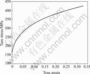
Fig.1 True stress��strain curve of 3A21 aluminum
Table 1 Material parameters of 3A21 aluminum
The strain states used to determine the strain limit are commonly obtained via the dome test procedure, where grid markings (d 2.5 mm circular grid) are etched onto the surface of specimens. In these tests, various strain states are achieved by adjusting different parameters like the lubrication conditions between the sheet metal and the specimen width. The width varies at 180, 160, 140, 120, 100, 80, 60, 40 and 20 mm. Length of all specimens is 180 mm. For all the specimens, the length is along the rolling direction, while the width is along the transverse direction. The velocity of punch is 10 mm/min, and the binder force is 20 kN.
The stamped specimens are shown in Fig.2. After the desired deformation is achieved, the geometry of the markings near a neck or fracture is analyzed in order to calculate and record various strain states associated with the strain limit. By altering the strain ratio within the principal strain coordinates, from uni-axial tension to equi-biaxial tension, a theoretical FLD with damage consideration can be determined (see Fig.3).
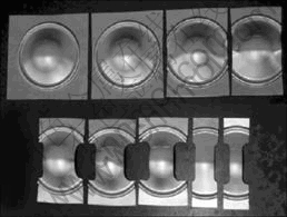
Fig.2 Sample of stamped 3A21 sheet specimens
2.2 Transformation between stress and strain states
The strain-path dependent nature of the FLD causes the method to become ineffective in the analysis of complex forming process such as restrikes, flanging operations and hydroforming. The stress-based forming limit diagram(FLSD) established with limit stress is independent of the strain paths. Compared with traditional strain-based FLD, it is more convenient and practical to use as the criterion of forming limit under complex strain paths.
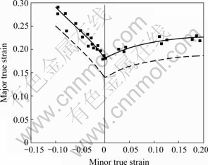
Fig. 3 FLD of 3A21 aluminum
Using the formula of STOUGHTON[8] for transformation between stress and strain states, and omitting the thickness stress of sheet (��3=0), the state is plane-stress condition, then the ratio of the minor true stress, ��2, to the major true stress, ��1, is defined by the parameter
��=��2/��1 (2)
The plasticity theory defines an effective stress, ![]() which is a function of the stress tensor components and a set of material parameters. In this case, the definition of the effective stress can be expressed in terms of the principal stresses:
which is a function of the stress tensor components and a set of material parameters. In this case, the definition of the effective stress can be expressed in terms of the principal stresses:
![]() (3)
(3)
This relation can also be expressed as follows:
![]() (4)
(4)
where ��(��) is a function of material parameters.
Similarly, the ratio of the minor true strain increment, d��2, to the major true strain increment, d��1, is defined by the parameter
��=d��2/d��1 (5)
The effective strain is defined by the time integral of the effective strain increment:
![]() (6)
(6)
where ��(��) is a function of the material parameters.
The relation between the effective stress and effective strain can be written formally as
![]() (7)
(7)
Then, the relation between �� and �� can be expressed as
��=��(��) (8)
The transformation from the strain states to the stress states can be defined using the above equations. If the prestrain results in a strain state (��1i, ��2i), the secondary stage results in a final strain state (��1f, ��1f), then the principal stresses at the end of the secondary stage are given by
![]() (9)
(9)
![]() (10)
(10)
The above two relations allow us to map each point on the strain-based forming limit curves into stress space for each of the prestrained conditions, as well as for the as-received material (��1i=��2i=0). Fig.4 shows the FLSD of 3A21 transformed form FLD shown in Fig.3 using the above transformation formulas.
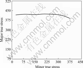
Fig.4 Forming limit stress diagram(FLSD) of 3A21 aluminum
3 Application of FLSD to hydroforming
3.1 Hydroforming of automotive members
Tube hydroforming process has drawn increasing attention in the automotive industry because of its enormous advantages over traditional processes. Since automotive parts have various different design shapes according to automobile makers, the process is mainly used to produce tube-like products with varying cross-sectional shapes along the length direction[11]. During the hydroforming process, since axial feeding provides limited material flow due to friction and the die geometry constraint, only pure expansion occurs at the middle section. At this time, crushing processes combined with performing and hydroforming become important approaches for hydroforming a circular tube into various cross-sections. Fig.5 shows a sample of hydroformed automotive framework. For convenience, a unit length of a component with square cross-section is extracted for research in the following context. As the tube with circular cross-section expands, it comes into contact with the die, the portion that is in contact with the die is acted upon by internal fluid pressure and frictional force (due to tube-die friction). This portion of the tube is under a three-dimensional state of stress. The other portion of the tube, which is not in contact with the die, is approximately under a plane stress loading condition and the plastic strain is higher in this portion. However, if a sufficient length of the three-dimensional portion is in contact with the tube, the frictional force is large enough to retard material flow from three- dimensional portion into plane stress portion. Consequently, instability develops at the interface of the three-dimensional and the plane stress portions and a neck forms. The critical conditions for the formation of the neck are therefore the frictional force and the through thickness component of compressive stress.
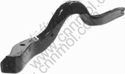
Fig.5 Hydroformed automobile framework
3.2 Application of FLSD in FEM simulations
3.2.1 Finite element modeling
A dynamic explicit FEA software ��LS-DYNA�� is adopted to analyze the plastic flow pattern of a circular tube expanded into a square cross-section die. Both ends of the tube were constrained in order to inhibit the axial displacement. The dimensions of the tube were 50 mm in outer diameter, 100 mm in length and 2 mm in wall thickness. Due to symmetry, only a quarter of the tube was modeled. Four-node Belytschko-Tsay shell elements were employed for the tube in the simulation due to its computational efficiency and accuracy, and the die is modeled as a rigid surface. The interface between the tube and the die was modeled with an advanced automatic surface-to-surface contact algorithm with an elastic coulomb friction law, with a coefficient of friction of 0.05. Fig.6 shows the loading path of the internal pressure adopted in simulation, where the limit pressure is 80 MPa, and the total computational time is 0.01 s. The material is assumed to obey Hill��s normally anisotropic plasticity theory. The mechanical properties of the tube adopted are summarized in Table 1 and Fig.1.
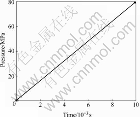
Fig.6 Loading path of hydroforming
3.2.2 Results and discussion
Fig.7 shows the numerical simulation results of the evolution of the cross-section thickness distribution for different forming stages. From the figure, it can be seen that at the early stage of the expansion (1.3 ms) process, the thickness distribution of the tube is uniform; at the later stage (4.6 ms), a gradually increased pressure is placed on the tube, the thickness becomes more non-uniformly distributed. From the FE-simulations, it is noteworthy that the minimum thickness occurs at the very intersection of the expansion part (plane stress portion) and the contact part (three-dimensional portion) at each stage of the process.
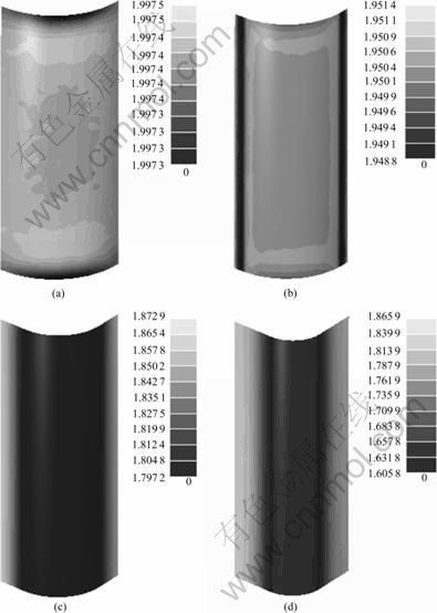
Fig.7 Distributions of thickness for different forming stages: (a) 1.3 ms; (b) 2.5 ms; (c) 3.8 ms; (d) 4.6 ms
Fig.8 shows the thickness strain distribution of the cross-section of the tube at 6.3 ms. It is obvious that the minimum thickness strain also occurs in the transition region. This location is where the tube will eventually fail.
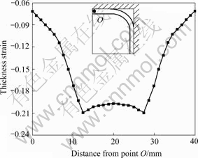
Fig.8 Thickness strain distribution at 6.3 ms
This section presents results of the computations, where the FLSD has been used to predict the onset of the neck. Fig.9 shows the stress paths of three typical elements selected in the cross-section of the tube. Also in Fig.9, the determined stress-based forming limit curves are shown.
Point A is located at the straight side of the tube; the stress path is plotted with respect to the FLSD, as shown in Fig.9(a). At the early stage of the expansion, the portion where A point is located is acted upon only by internal fluid pressure, the stress path is almost linear. At 3.75 ms when this portion comes into contact with the die, the elements experience through-thickness component of compressive stress and there is a decrease in the mean stress that is predominantly tensile until this time. Therefore, the mean stress decreases and the load path acquires a negative slope. It can be seen that the stress path at location A does not cross the FLSD.
Fig.9(b) shows the stress path of Point B which is located at the transition region at the late stage of the expansion. The stress path of point B crosses the FLSD at 5.9 ms in the figure. This is because the tube here is subjected to compressive stress at the final stage of the process, as well as tensile stress in the circle during the entire process. The pressure at 5.9 ms is 46.4 MPa and corresponds to the necking pressure.
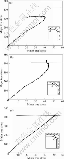
Fig.9 Stress paths for typical positions in cross-section of tube: (a) Stress path of point A; (b) Stress path of point B; (c) Stress path of point C
Point C is located at the corner region during the entire expansion process. The deformation of this region can be assumed as a plane strain model, and the stress path of point C is shown in Fig.9(c). The stress path crosses the FLSD at 6.3 ms and corresponding necking pressure is 50.4 MPa.
The comparison of three stress paths in Fig.9 shows that the stress path of point B crosses the FLSD first. That is the necking and failure in this case occurs primarily at the transition region between corner and straight side.
4 Experiments on tube hydroforming
Fig.10 shows the sample formed into a square cross- section with a 3A21 aluminum alloy extruded tube.
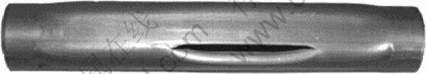
Fig.10 Sample of hydroformed square cross-section tube
The dimensions of the tube used in the experiment are the same as the FE-model��s. The fluid pressure was increased till the tubes burst and no end feeding was applied in these experiments. The bursting occurred in the very intersection of the free expansion region and the contact region, rather than in the corner region. The pressure at the onset of bursting was found to be 42.6 MPa. It agrees with the predicted value of 46.4 MPa.
References
[1] HARTL C. Research and advances in fundamentals and industrial applications of hydroforming [J]. J Mater Process Technol, 2005, 167(2): 383-392.
[2] DOHMANN F, HARTL C. Hydroforming-applications of coherent FE-Simulations to the development of product and processes [J]. J Mater Process Technol, 2004, 150(3): 18-24.
[3] KOC M, ALTAN T. An overall review of the tube hydroforming technology [J]. J Mater Process Technol, 2001, 108(2): 384-393.
[4] HAMA T, ASAKAWA M, MAKINOUCHI A. Investigation of factors which cause breakage during the hydroforming of an automotive part [J]. J Mater Process Technol, 2004, 150(3): 10-17.
[5] KLEEMOLA H J, PELKKIKANGAS M T. Effect of predeformation and strain path on the forming limits of steel, copper and brass [J]. Sheet Metal Ind, 1977, 63(6): 591-599.
[6] GRAF A, HOSFORD W. The influence of strain-path changes on forming limit diagrams of A16111-T4 [J]. International J Mater Process Technol, 1994, 36(10): 897-910��
[7] ARROUX R, BEDRIN C, BOIVIN M. Determination of an intrinsic forming limit stress diagram for isotropic metal sheets [C]// Proceeding of the 12th Biennial Congress IDDRG, 1982: 61-71.
[8] STOUGHTON T B. A general forming limit criterion for sheet metal forming [J]. International Journal of Mechanical Sciences, 2000, 42(1): 1-27.
[9] KEELER S. Circular grid system-a valuable aid for evaluating sheet metal formability [P]. USA, SAE 680092, 1965.
[10] GOODWIN G M. Application of strain analysis to sheet metal forming in the press shop [P]. USA, SAE 680093, 1968.
[11] HWANGA Y M, ALTAN T. Finite element analysis of tube hydroforming processes in a rectangular die [J]. Finite Elements in Analysis and Design, 2002, 39: 1071-1082.
Foundation item: Project(06012150C) supported by the Fund for Key Program of the ��11th 5-year Plan�� of Anhui Province, China
Corresponding author: XUE Ke-min, Tel: +86-551-2904758; E-mail: xuekm0721@sina.com
(Edited by PENG Chao-qun)
