
J. Cent. South Univ. Technol. (2011) 18: 1985-1993
DOI: 10.1007/s11771-011-0932-y![]()
Geometry effect on mechanical properties of woven fabric composites
KIM Myungsoo, SONG Jung-Il
School of Mechatronics, Changwon National University, Changwon 641-773, Korea
? Central South University Press and Springer-Verlag Berlin Heidelberg 2011
Abstract:
The effects of geometry on mechanical properties in woven fabric composites were explored. Two types of composites, including one-layered and two-layered composites, were designed and studied. For one-layered composites, inter-strand gap effects on the mechanical properties were studied, while three cases of geometries with inter-strand gaps in two-layered composites were evaluated. A woven fiber micromechanics analytical model called MESOTEX was employed for theoretical simulation. The predicted results show that the inter-strand gap and simple variation of the strand positions in a repeating unit cell significantly affect the mechanical properties of woven fabric composites.
Key words:
woven fabric composites; inter-strand gap; mechanical properties; micromechanics modeling��
1 Introduction
Recently, there has been growing interest in woven fabric composites. The use of woven fabric composites is increasing in the fields of aeronautics [1-2], automobile engineering [3-4], and military equipment [5-6]. This increase of practical application has encouraged the development of micromechanics models for analyzing woven fabric composites, and several models have been proposed [7-12]. SCIDA et al [7-8] developed a micromechanical model called MESOTEX to determine the elastic properties of composites reinforced with either non-hybrid weave or hybrid weave. To take into account the geometry of woven fabric, AITHARAJU and AVERILL [9] divided a repeating unit cell into three regions depending on the tow waviness: a cross-ply region, fiber waviness in one direction and fiber waviness in two directions. HUANG [10] proposed a micromechanics model to predict the mechanical properties of composites reinforced with woven and braided fabrics. BYSTR?M et al [11] noted that the architecture of the reinforcement in woven composites may have a significant effect on the mechanical properties.
Thus far, limited researches have been devoted to the effects of inter-strand gap on the mechanical properties of woven fabric composites. Most studies just predicted the mechanical properties of woven fabric composites with one layer of repeating unit cells. Moreover, few works have studied the effect of geometry in relation with inter-strand gaps in multi-layered woven fabric composites. It can be reasonably speculated that the inter-strand gaps may significantly affect the bulk mechanical properties of composites. Upon this background, the inter-strand gap effects on mechanical properties of one-layered and two-layered composites were studied through a numerical simulation in this work.
2 Numerical modeling
2.1 Woven fiber micromechanics
The woven fiber micromechanics model MESOTEX [7-8] was employed to study the effects of geometry on the mechanical properties of woven fabric composites. The micromechanics model employed classical laminate theory [13-14] to consider strand undulations and integrate the geometrical and mechanical parameters of each constituent (resin, fill and warp strands). The elastic properties of woven fabric composites were obtained from the properties of a repeating unit cell that represents the woven fabric composites. Therefore, the elastic properties obtained from the stiffness matrix of a repeating unit cell were considered to be the bulk mechanical properties of the woven fabric composites. The identification of the relation between elastic properties and the stiffness matrix can be seen in Ref.[15].
The stiffness matrix C for a repeating unit cell can be expressed as the summation of the stiffness matrices of the fill strand (tow), warp strand (tow), and polymer resin matrix [8]:
![]() (i, j=1, ��, 6) (1)
(i, j=1, ��, 6) (1)
where ![]() is the transformed stiffness matrix for the ��I�� element, and the superscript ��I�� denotes either the fill strand (F), the warp strand (W), or the matrix (M). VI is the volume fraction of the ��I�� element in a slice in a repeating unit cell. Equation (1) expresses the classical thin laminate theory of fill and warp strands and the matrix at each point (x1, x2) [7].
is the transformed stiffness matrix for the ��I�� element, and the superscript ��I�� denotes either the fill strand (F), the warp strand (W), or the matrix (M). VI is the volume fraction of the ��I�� element in a slice in a repeating unit cell. Equation (1) expresses the classical thin laminate theory of fill and warp strands and the matrix at each point (x1, x2) [7].
Equation (2) is an expression of ![]() which is a 6��6 stiffness matrix transformed with respect to a global coordinate system for the ��I�� element [8]:
which is a 6��6 stiffness matrix transformed with respect to a global coordinate system for the ��I�� element [8]:
![]() (2)
(2)
where RI is the Reuter matrix; QI is the stiffness matrices for the fill and warp strands and polymer matrix; T I is the transformation matrix for the fill and warp strands. The fill and warp strands were considered, locally, to be unidirectional continuous fiber composites whose principal direction corresponds to the direction of the weave, dependent on the fiber direction and undulation. To obtain the stiffness matrices QI of the fill and warp strands, the Mori-Tanaka micromechanics model [16] was employed. The transformation matrix T I was used to rotate the stiffness matrix expressed in its principal reference frame into the global reference frame accounting for spatial dependence of the stiffness [8]. The elements of the transformation matrix depend on the types of woven fabric. A plane woven fabric was selected for the present work.
As noted earlier, two kinds of composites were studied, including one layered composites and two layered composites. To study the effect of inter-strand gaps in the one layered composites, the fill and warp strands were designed with gaps ranging from 0 to 1.6 mm as shown in Figs.1 and 2. Figure 1 shows the computer generated fill and warp strands. The equations were implemented in a simulation code using MATLAB to generate the geometrical configurations of the plane woven fabric. Figure 2 schematically illustrates the one-layered composites.
The geometry information of the strands, as shown in Fig.2, includes orientation and local off-axis angles (��f for fill strand and ��w for warp strand) [7-8]. As expressed in Eqs.(3) and (4), the off-axis angles are obtained using two undulations of the strands, Hf and Hw, the undulations along the x1 and x2 axes of the median fiber of the fill and warp strands, respectively [7-8]:
![]() (3)
(3)
![]() (4)
(4)
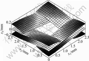
Fig.1 Computer generated fill and warp strands

Fig.2 Schematic diagrams of fill and wrap strands (one-layered composites, ��f and ��w: Local off axis angles of fill and warp strands): (a) Top view; (b) Side view (along x2 axis); (c) Side view (along x1 axis)
The undulations of the fill strands along the x1 axis for Fig.2 are expressed as
![]() (0��x1��auc) (5)
(0��x1��auc) (5)
where hf and auc are the maximum thickness of the fill strands and the width of a unit cell, respectively.
The thickness of the fill strand along the x2-axis is written as
 (6)
(6)
where ag is the width of the gap between strands.
Similar expressions are acquired for the undulation of the warp strands in Fig.2:
![]() (0��x2��auc) (7)
(0��x2��auc) (7)
 (8)
(8)
where hw is the maximum thickness of the warp strands.
For the two-layered composites, three different geometry cases were designed, as shown in Figs.3-5. Both the upper and lower layers in the two-layered composites have the same inter-strand gap width of 0.8 mm (aw/2). The geometry of the one-layered composites shown in Fig.2 was also used for the lower layers in the cases of two-layered composites. The upper layers of the cases, however, have different geometries as a result of changing the positions of the fill and warp strands. For the upper layer in Case 1 in Fig.3, Eqs.(5)- (8) used for the one-layered composites were also employed. The upper layers for Cases 2 and 3 in Figs.4 and 5 were designed using Eqs.(9)-(12) and Eqs.(13)- (16), respectively.
![]() 0��x��auc (9)
0��x��auc (9)
 (10)
(10)
![]() 0��x2��auc (11)
0��x2��auc (11)
![]() (12)
(12)
![]() 0��x1��auc (13)
0��x1��auc (13)
![]() ,
, ![]() (14)
(14)
![]() 0��x2��auc (15)
0��x2��auc (15)
![]() ,
, ![]() (16)
(16)
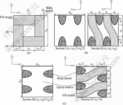
Fig.3 Schematic diagrams of two-layered composite (Case 1): (a) Top view; (b) Cross section (along x2 axis); (c) Cross section (along x1 axis)
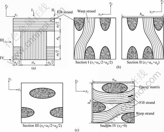
Fig.4 Schematic diagrams of two-layered composite (Case 2): (a) Top view; (b) Cross section (along x2 axis); (c) Cross section (along x1 axis)
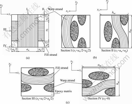
Fig.5 Schematic diagrams of two-layered composite (Case 3): (a) Top view; (b) Cross section (along x2 axis); (c) Cross section (along x1 axis)
Before using, the micromechanics model should be validated in order to avoid miscalculations on the prediction of mechanical properties. In order to verify if the model was coded correctly, the simulation results of E-glass/vinylester plane woven composites were compared with the results presented in Ref.[8]. The mechanical properties of E-glass fiber, vinylester and E-glass/vinylester strands as well as the geometry parameters of the plain woven composites used in Ref.[8] were employed in the simulation. Table 1 presents the results for the comparison. The small differences between the values from the present work and the model in Ref.[8] were expected to come from the difference of the numbers of finite calculation points on x1 and x2 axes in the repeating unit cell during the calculation. Judging from the results, it is concluded that the model was coded correctly.
Table 1 Simulation results of E-glass plane woven fabric/ vinylester composites

2.2 Fiber volume fraction
The fiber volume fraction in a repeating unit cell is determined by the strand volume fraction in the repeating unit cell and the fiber volume fraction within the strands. The strand volume fraction is obtained using the strand undulation within the repeating unit cell and the associated geometrical parameters, such as the strand width and thickness. The fiber volume fraction vf is thus expressed as [7]
![]() (17)
(17)
where vf/s is the fiber volume fraction in the strand, and as, hs, and Ls are the strand width, thickness and the undulation length of the strands, respectively; auc and huc are the width and thickness of the repeating unit cell, respectively.
3 Results and discussion
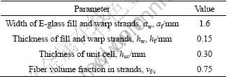
An epoxy polymer was employed for the isotropic matrix for the simulation. The elastic modulus and Poisson ratio of the polymer matrix are 3.0 GPa and 0.3, respectively [13-14]. IM7 carbon fibers were used for fiber reinforcement. The fibers were assumed to be isotropic with an elastic modulus of 276 GPa and a Poisson ratio of 0.2 [13-14]. Table 2 gives the geometry parameters and volume fraction of fibers in the strands. The predicted results are shown as the ratio of the resultant values to the control values and Table 3 gives the control values of the one-layered and two-layered composites.
Table 2 Geometry parameters and fiber volume fraction in strands
3.1 Inter-strand gap effect in one-layered composites
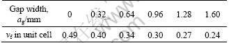
The fiber volume fraction in a repeating unit cell, which significantly affects the unit cell in terms of mechanical properties, was obtained using the parameters in Table 2. Table 4 provides the fiber volume fraction in a repeating unit cell with respect to the width of the inter-strand gap. As the width of the inter-strand gap increases, the fiber volume fraction decreases.
Table 3 Control values of one-layered and two-layered composites
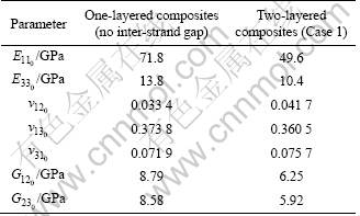
Table 4 Fiber volume fraction vf in repeating unit cell under different inter-strand gap width
Figures 6-8 show the theoretical simulation results of one-layered composites. Since the fiber volume fraction in Table 4 decreases with the increase of the inter-strand gap width, the elastic modulus decreases as the gap width increases, as seen in Fig.6. The elastic modulus E11, along the x1 axis, is reduced by 47% (from 71.8 GPa with no inter-strand gap to 38.2 GPa with 1.6 mm inter-strand gap width).
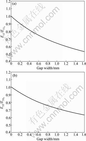
Fig.6 Elastic moduli of one layered composites: (a) E11 along x1 axis; (b) E33 along x3 axis
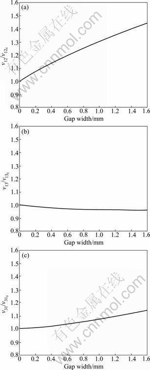
Fig.7 Poisson ratios of one-layered composites: (a) ��12 on x1-x2 plane; (b) ��13 on x1-x3 plane; (c) ��31 on x3-x1 plane
The Poisson ratios in Fig.7 reveal interesting phenomena. First, as the inter-strand gap width increases, the volume fraction of the epoxy matrix, whose Poisson ratio (0.3) is higher than that of carbon fiber (0.2), increases. This may account for the increasing trend of ��12 as the gap width increases. ��12 increases from 0.033 4 at no gap to 0.046 9 at 1.6 mm gap width. The same explanation can be applied to the Poisson ratio ��31 in Fig.7(c), although the increment of ��31 is not as large as that of ��12. The stiffness of the composites along the x1 axis decreases in proportion to the increase of the epoxy matrix. However, the compressive stiffness along the x3 axis does not decrease substantially with the increase of the amount of the epoxy matrix due to the thickness of the fiber strands. This might generate the small decrease of ��13 as seen in Fig.7(b) (0.373 8 at no gap to 0.358 6 at 1.6 mm gap width).
Figure 8 provides the shear moduli of one-layered composites, showing similar trends with the elastic moduli in Fig.6. When the inter-strand gap size increases, the volume fraction of the polymer matrix in the composites increases. Therefore, the shear moduli, G12 and G23, decrease with the increase of gap width. The shear modulus G12 of the composites with 1.6 mm gap is 43% lower than the modulus of the composites without inter-strand gap.
As explained above, the inter-strand gap significantly affects the mechanical properties of the composites. Therefore, this parameter should be taken into consideration during the design of woven fabric composites.

Fig.8 Shear moduli of one layered composites: (a) G12 on x1-x2 plane; (b) G23 on x2-x3 plane
3.2 Geometry effect on mechanical properties of two layer composites
As noted in Section 2, three geometry cases for two-layered composites were studied. To generate fill and warp strands, all except the unit cell thickness of the geometry parameters in Table 2 were employed. The thicknesses of the repeating unit cells were changed due to the geometry of the three cases (0.6 mm, 0.56 mm, and 0.48 mm for Cases 1, 2 and 3, respectively). This leads to the variation in the fiber volume fractions of the three cases. The fiber volume fraction of Cases 1, 2 and 3 are 0.32, 0.35, and 0.40, respectively.
Figures 9-11 show the predicted mechanical properties of the different composites. In Fig.9, the elastic modulus of Case 3 is the highest, because this composite has the highest fiber volume fraction (0.40) among the three cases. In Fig.9(a), the elastic modulus E11 in Case 3 is increased by 23% from the modulus for Case 1 by simply changing the positions of the strands in the upper layer.
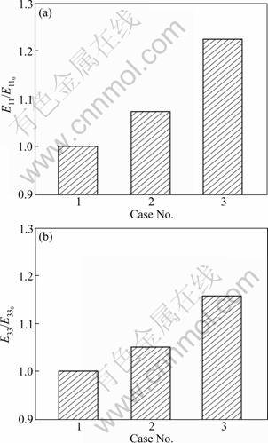
Fig.9 Elastic moduli of two-layered composites: (a) E11 along x1 axis; (b) E33 along x3 axis
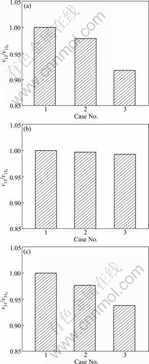
Fig.10 Poisson ratio of two-layered composites: (a) ��12 on x1-x2 plane; (b) ��13 on x1-x3 plane; (c) ��31 on x3-x1 plane
As the fiber volume fraction fraction is increased in the three cases, the Poisson ratio decreases, as seen in Fig.10. The decrease amount of the resulted ratio of ��12 and ��31 are relatively larger compared to that of ��13.
The shear moduli show a similar trend with the elastic moduli in Fig.9, that is, the shear moduli increase as the fiber volume fraction increases. Compared to Case 1, Case 3 shows almost a 20% improved shear modulus.
In the two-layered composites, three different geometries were studied. The mechanical properties were improved considerably by simply changing the geometries of the upper strands.
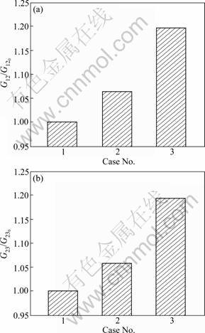
Fig.11 Shear moduli of two-layered composites: (a) G12 on x1-x2 plane; (b) G23 on x2-x3 plane
4 Conclusions
1) In the one-layered composites, an increase of inter-strand gap width causes the increase of elastic and shear moduli and the decrease of fiber volume fraction. However, some of Poisson ratios (��12 and ��31) increase because of the increase of the matrix volume fraction.
2) In the three cases of the two-layered composites, Case 3 shows higher elastic and shear moduli with a higher fiber volume fraction. The elastic modulus (E11) and shear modulus (G12) of Case 3 are increased by 23% and 20%, respectively, compared to Case 1. On the contrary, the Poisson ratios (��12, ��13 and ��31) decrease as the fiber volume fraction increases.
References
[1] JONES J S, POLIS D L, ROWLES R R, SEGAL K N. Comparative study of 3-dimensional woven joint architectures for composite spacecraft structures [C]// Proceedings of International SAMPE Technical Conference. Forth Worth: Society for the Advancement of Material and Process Engineering. 2011: 1-18.
[2] WAMBUA P M, ANANDJIWALA R. A review of performs for the composites industry [J]. Journal of Industrial Textiles, 2011, 40(4): 310-333.
[3] LUAN K, SUN B, BU B, ZHANG J. Design of an eco-power automobile body made from green composite and its structural optimization in FEA [J]. Advanced Materials Research, 2011, 287/288/289/290: 405-409
[4] POORZEINOLABEDIN M, GOLZAR M. Improving the woven glass/epoxy composite for automobile exterior body cover [J]. Materials and Manufacturing Processes, 2011, 26(4): 562-566.
[5] JIN L, SUN B, GU B. Finite element simulation of three-dimensional angle-interlock woven fabric undergoing ballistic impact [J]. Journal of the Textile Institute, 2011, 102(11): 982-993.
[6] MAMIVAND M, LIAGHAT G H. A model for ballistic impact on multi-layer fabric targets [J]. International Journal of Impact Engineering, 2010, 37(7): 806-812.
[7] SCIDA D, ABOURA Z, BENZEGGAGH M L, BOCHERENS E. Prediction of the elastic behaviour of hybrid and non-hybrid woven composites [J]. Composites Science and Technology, 1997, 57(12): 1727-1740.
[8] SCIDA D, ABOURA Z, BENZEGGAGH M L, BOCHERENS E. A micromechanics model for 3D elasticity and failure of woven-fibre composite materials [J]. Composites and Science and Technology, 1999, 59(4): 505-517.
[9] AITHARAJU V R, AVERILL R C. Three-dimensional properties of woven-fabric composites [J]. Composites and Science and Technology, 1999, 59(12): 1901-1911.
[10] HUANG Z M. The mechanical properties of composites reinforced with woven and braided fabrics [J]. Composites and Science and Technology, 2000, 60(4): 479-498.
[11] BYSTR?M J, JEKABSONS N, VARNA J. An evaluation of different models for prediction of elastic properties of woven composites [J]. Composites: Part B, 2000, 31(1): 7-20.
[12] KIM M, PARK Y B, OKOLI O I, ZHANG C. Processing, characterization, and modeling of carbon nanotube-reinforced multiscale composites [J]. Composites Science and Technology, 2009, 69(3/4): 335-342.
[13] MALLICK P K. Fiber-reinforced composites [M]. 2nd Ed. New York: Marcel Dekker, Inc., 1993: 15-90.
[14] BARBERO E J. Introduction to composite materials design [M]. New York: Taylor & Francis, 1999: 15-41.
[15] JONES R M. Mechanics of composite materials [M]. 2nd Ed. Philadelphia: Taylor & Francis, Inc., 1999: 55-88.
[16] ASHRAFI B, HUBERT P, VENGALLATORE S. Carbon nanotube- reinforced composites as structural materials for microactuators in microelectromechanical systems [J]. Nanotechnology, 2006, 17(19): 4895-4903.
(Edited by HE Yun-bin)
Foundation item: Work supported by the Second Stage of the Brain Korea 21 Projects
Received date: 2011-05-24; Accepted date: 2011-10-10
Corresponding author: SONG Jung-Il, Professor, PhD; Tel: +82-55-213-3606; E-mail: jisong@changwon.ac.kr
Abstract: The effects of geometry on mechanical properties in woven fabric composites were explored. Two types of composites, including one-layered and two-layered composites, were designed and studied. For one-layered composites, inter-strand gap effects on the mechanical properties were studied, while three cases of geometries with inter-strand gaps in two-layered composites were evaluated. A woven fiber micromechanics analytical model called MESOTEX was employed for theoretical simulation. The predicted results show that the inter-strand gap and simple variation of the strand positions in a repeating unit cell significantly affect the mechanical properties of woven fabric composites.
