
Article ID: 1003-6326(2005)06-1264-11
Effect of mandrel on cross section quality of
thin-walled tube numerical controlled bending
GU Rui-jie(�����), YANG He(�� ��),
ZHAN Mei(ղ ÷), LI Heng(�� ��), WANG Guang-xiang(������)
(College of Materials Science and Engineering, Northwestern Polytechnical University,
Xi��an 710072, China)
Abstract:
The effect of mandrel with the structure of ball and socket on the cross section quality of thin-walled tube numerical controlled(NC) bending was studied by numerical simulation method, combined with theoretical analysis and experiment. Influencing factors of the mandrel include the count of mandrel heads, the diameter of mandrel and its position. According to the principle of NC tube bending, quality defects possibly produced in thin-walled tube NC bending process were analyzed and two parameters were proposed in order to describe the cross section quality of thin-walled tube NC bending. According to the geometrical dimension of tube and dies, the range of mandrel protrusion was derived. The finite element model of thin-walled tube NC bending was established based on the DYNAFORM platform, and key technological problems were solved. The model was verified by experiment. The effect of the number of mandrel heads, the diameter of mandrel and the protrusion length of mandrel on the cross section quality of thin-walled tube NC bending was revealed and how to choose mandrel parameters was presented.
Key words:
thin-walled tube; numerical controlled(NC) tube bending; mandrel; cross section quality; simulation CLC;
number: TG386.41 Document code: A
1 INTRODUCTION
Thin-walled tube bending parts have been increasingly used in many industry fields such as aviation, aerospace and automobile for their easy satisfaction in light-mass, high strength and low consuming. The numerical controlled(NC) rotary-draw tube bending craft not only enables high technicalization of the forming process of tube plastic bending, but also can satisfy requirements of high precision, high efficiency, digitalization and intellectualization. So in aviation, aerospace and automobile industries, cold NC tube bending process has been developed as one of the most important traditional tube bending crafts[1].
However, thin-walled tube in NC bending process may wrinkle and its cross section may distort especially for tube bending with large diameter and small bending radius, so a mandrel is used to support the wall in the tube in order to prevent the inner layer of bending tube from wrinkling and diminish distortion of cross section. Now mandrel with the structure of ball and socket is generally adopted in thin-walled tube NC bending, which includes mandrel body and mandrel heads. The diameter of mandrel, its position and the number of mandrel heads have a significant effect on the quality of thin-walled tube NC bending. When the diameter of mandrel and its position are properly chosen, cracking and wrinkling can be avoided in the process, but cross section distortion and wall thinning can��t be controlled in effect. The reasonable number of mandrel heads, the diameter of mandrel and its position need to be determined in order to gain qualified bending tube in production, by which cross section distortion and wall thinning can be controlled in effect. However, up till now, much research work puts emphasis on tube bending[2-15], but the reported literatures on mandrel[16, 17] are scant. The effect of mandrel with the structure of ball and socket on the cross section quality of thin-walled tube NC bending is studied by numerical simulation method, combined with theoretical analysis and experiment. Influencing factors of the mandrel include the number of mandrel heads, the diameter of mandrel and its position. The achievements of this study is useful to determining the reasonable number of mandrel heads, diameter of mandrel and its position in the process, and the method of numerical simulation research can be used to study the effects of other parameters on the forming quality of NC tube bending.
2 PARAMETERS FOR DESCRIBING CROSS SECTION QUALITY OF THIN-WALLED TUBE NC BENDING
Fig.1 shows the sketch of the NC tube bending process. Bending die is fixed on the major axes of machine tool and revolves together with the major axes. The leading end of tube is pressed tightly on the bending die, pressure die is set on outer wall, wiper die on inner wall of tube bending and mandrel in the tube at the tangency point between the tube and bending die. When bending die revolves, the tube is bent and formed gradually into the desired bending shape under the cooperation of the clamp die, the pressure die and the bending die.
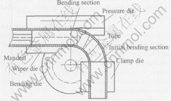
Fig.1 Sketch of NC tube bending process
In the process, the outer material of bending tube will be elongated under stretch stress in the tangential direction, which leads to wall thinning, and the inner material of bending tube will be shortened under pressure stress in the tangential direction, which leads to wall thickening. Fig.2 shows the stress and strain of the NC tube bending process.
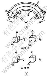
Fig.2 State of stress and strain during tube bending
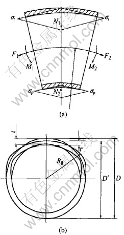
Fig.3 Cross sections distorting and wall thinning of tube bending
For thin-walled tube, the outer wall thinning of bending tube may be excessive because of too large tangential tensile stress, which leads to cracking. And the inner wall thickening may be excessive because of too big tangential pressure stress, which leads to wrinkling. Meanwhile the composite force of tangential stress causes cross sections distort (as shown in Fig.3). Precision forming and good section quality in this paper are referred to decreasing cross section distortion and wall thinning as far as possible when cracking and wrinkling are avoided.
The cross section distortion is generally thought to be similar to ovalization, but in fact during the process of thin-wall tube NC bending, the cross section distortion of tube mainly concentrates on the outer layer of tube and the cross section distortion of tube��s inner layer is very small because of the restriction of bending die. The authors use the changing ratio of the vertical axes (��D) to describe the degree of the cross section ovalization of thin-wall tube NC bending.
![]()
where D is the length of cross section��s vertical axes before bending, D�� is the length of cross section��s vertical axes after bending.
The wall largest thinning of every cross section is on the outermost layer of the section. So the authors use the ratio of wall thinning on the outermost layer of the section (��t) to describe the degree of wall thinning of thin-wall tube NC bending.
![]()
where t is the wall thickness on the outermost layer of the section before bending, t�� is the wall thickness on the outermost layer of the section after bending.
3 THEORETICAL PROTRUSION LENGTH OF MANDREL
Now mandrel with the structure of ball and socket is generally adopted in thin-walled tube NC bending, which includes mandrel body and mandrel heads (as shown in Fig.4). The position of mandrel body can be adjusted. Mandrel heads is jointed on mandrel body and the number of mandrel heads can be changed. The major role of mandrel body is to prevent inner layer of tube from wrinkling coordinating with wiper die and it also makes contributions to decrease cross section distortion in the degree. The major role of mandrel heads is to decrease the cross section distortion of tube bending. The diameter of mandrel, its position and the number of mandrel heads have significant effect on the quality of thin-walled tube NC bending. Wrinkling of inner layer under pressure stress can��t be effectively prevented when the diameter of mandrel is excessively small or the protrusion of mandrel is not long enough, and cross section distortion can��t be effectively decreased when the number of mandrel heads is not enough. But the mandrel will holdback tube bending when the diameter of mandrel is excessively large or the protrusion of mandrel is excessively long and mandrel heads are too many, which leads bending tube to gooseneck booming, even cracking. The reasonable number of mandrel heads, the diameter of mandrel and its position need to be determined in order to gain qualified bending tube in the production, by which cross section distortion and wall thinning can be controlled in effect.
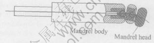
Fig.4 Structure of mandrel
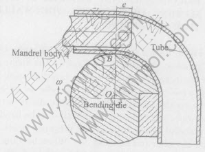
Fig.5 Sketch of mandrel protrusion length
Fig.5 shows the relative position between tube, mandrel body and bending die. The straight part of tube (AB) contacts bending die at the point of B, the length of mandrel body protruding into bending tube on the right of point B(e) is called mandrel protrusion length.
The whole structure of mandrel is cylinder and it is chamfered on the front end. The chamfered part does not contact with inside wall of tube before bending and its length is e2. So the mandrel protrusion length (e) includes the protrusion length of mandrel body cylinder part (e1) and the length of mandrel body chamfered part (e2), which can be expressed as e=e1+e2.
The major role of mandrel body is to support the wall in the tube so that it can prevent inner layer of tube under pressure stress wrinkling coordinating with wiper die. So the protrusion of mandrel body cylinder part should be beyond point B at least, expressed as e1��0. According to the geometrical dimension of tube and dies, the maximum of mandrel body protrusion can be determined. The mandrel chamfered part does not contact with inside wall of tube before bending, so mandrel protrusion length is the maximum mandrel body protrusion length when the end of mandrel body cylinder part (point E) contacts with the inside wall of bending tube. As shown in Fig.6, the maximum of mandrel body cylinder part protrusion length (e1max) is derived according to the geometry dimension of tube and dies when cross section distortion and wall thinning of bending tube are ignored.
In the right angled triangle Rt��OCE,
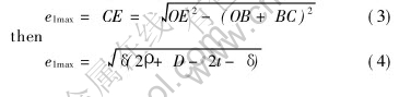
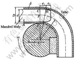
Fig.6 Maximum of mandrel protrusion length
because
emax=e1max+e2
then
![]()
where �� is the bending radius, D is the diameter of tube, t is the wall thickness, and �� is the clearance between mandrel and inside wall of tube.
Eqn.(5) is the formula of computing maximum mandrel protrusion length.
The clearance between mandrel and inside wall of tube (��) can be gained through the following formula:
��=D-2t-d(6)
where d is the diameter of mandrel.
It can be found from Eqn.(5) that the maximum of mandrel protrusion length is related to the bending radius (��), the diameter of tube (D), the wall thickness (t), the diameter of mandrel (d) and the length of mandrel body chamfered part (e2) when cross section distortion and wall thinning of bending tube are ignored.
The range of mandrel protrusion length without head is e1��e��emax according to the above analysis. The length of mandrel protrusion (e) derived in the work considers mandrel body chamfered part and �� in the formula of computing e1max is gained when mandrel contacts with inside wall of tube. Compared with Ref.[17], the present formula of computing mandrel protrusion length (e) derived in the paper is more corresponding to reality.
Because the mandrel heads of mandrel with the structure of ball and socket must be ensured to revolute freely and cross section distortion and wall thinning of bending tube are ignored when the range of mandrel protrusion length (e) is derived according to the geometrical dimension of tube and dies, the mandrel heads has no effect on mandrel theoretical protrusion length.
The derivation of mandrel theoretical protrusion length (e) provides a basis for the further research on mandrel protrusion length of tube bend-ing. The mandrel protrusion length (e) chosenfrom Eqn.(5) can effectively avoid defect and even the possibility of die damage when simulation research has not been done, which has been confirmed by experiment. Meanwhile the derivation of mandrel theoretical protrusion length (e) may serve as guide to simulation research, with which the count of simulation can be decreased and the efficiency of simulation can be improved.
4 FINITE ELEMENT SIMULATION MODEL OF THIN-WALLED TUBE NC BENDING
4.1 Establishment of thin-walled tube NC bending finite element simulation model and its key technologies
According to the principle of NC tube bending (as shown in Fig.1), the finite element model of thin-walled tube NC bending (as shown in Fig.7) based on the DYNAFORM platform is established.
4.1.1 Determination of loading way
NC tube bending is loaded through displacement. It��s easy to realize that bending die revolves around its own center and pressure die translates along X direction (as shown in Fig.7) in DYNAFORM. But because the reference point of die is its gravity center in DYNAFORM, it cannot be realized that clamp die revolves around the center of bending die with simple movement at one direction.
The upper clamp die and down clamp die are simplified one clamp die and its movement is divided into three movements at different direction including translation along the X direction, translation along the Y direction and revolution around the Z axes across the gravity center of clamp die. The movements are as follows:
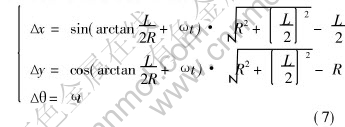
where R is the bending radius, L is the length of clamp die, �� is the angular speed of bending and t is the time.
4.1.2 Selection of element
Revised membrane element, solid element and shell element can be used in simulating thin-walled tube bending. Revised membrane element considers the influence of bending on the base of membrane element and revises membrane stress with bending stress. The efficiency of computing is high and its precision is low with revised membrane element. Both the precision and efficiency of computing are high with solid element for thick-walled parts. But the efficiency of computing is very low
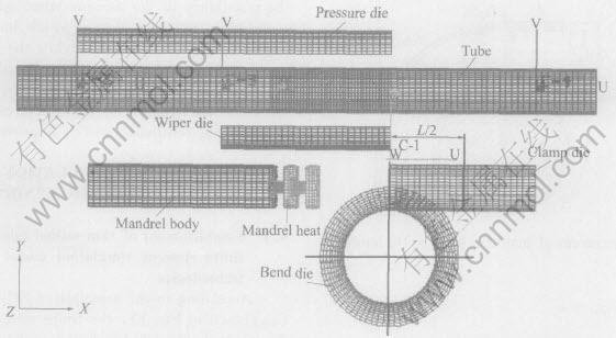
Fig.7 Finite element simulation model of thin-walled tube NC bending
for thin-walled parts because the part must be divided very densely into elements in order to avoid the oddity of the stiffness matrix. Because not only the precision but also efficiency of computing are high to simulate thin-walled parts forming with shell element, the tube is disposed into shell elements when thin-walled tube NC bending is simulated.
4.1.3 Selection of material model
The precision of simulation depends on whether material model reflects true characteristics of material. Because NC tube bending is a kind of cold bending craft and the material will get harden during bending, the model of index hardening material is chosen to simulate the forming of thin-walled tube NC bending. The relation of stress and strain can be expressed as
��=K��n(8)
where K is the stiffness factor, and n is the hardening index.
4.1.4 Determination of finite element computing algorithm
Static implicit algorithm and dynamic explicit algorithm can be used in the finite element simulation of thin-walled tube bending. The classic static implicit algorithm has so strict theoretical basis that the precision of computing are very high, but the convergence of computing may be bad and the efficiency of computing decreases greatly with the scale of the question increasing. So the efficiency of computing is very low when large scale forming is computed. The dynamic explicit algorithm is based on difference algorithm, which causes nonlinear equation explicit and iteration avoided. Not only the precision but also the efficiency of computing are high with dynamic explicit algorithm, so set of equations are computed with dynamic explicit algorithm in the work.
4.1.5 Treatment of contact boundary
It��s very important how to deal with contact boundary between the blank and die in the finite element simulation of plastic forming. The method of dealing with contact boundary includes Lagrange multiplier method and penalty function method. Lagrange multiplier method is to introduce Lagrange multiplier into set of equations so that the boundary condition can be satisfied, which ensures that contact points don��t penetrate through each other. Because Lagrange multiplier increases system��s degrees of freedom and causes stiffness matrix asymmetry, many times iteration is needed to convergence. The efficiency of computing with Lagrange multiplier method is low and the method suits to static computing. Penalty function method is to introduce contact condition into set of equations as penalty. Penalty function method doesn��t increase system��s degrees of freedom, so its computing efficiency is high. Penalty function method suits to explicit computing, so it is used to deal with contact constraint in the work.
4.1.6 Determination of friction model
During NC tube bending process, the friction has an important influence on the deformation, so it is necessary to introduce a proper friction model into the finite element simulation. Here, Coulomb friction model is used to compute friction, which ignores coherence and consider that friction is proportional to normal pressure. The mathematical expression of Coulomb friction model is
![]()
where �� is the equivalent shear stress, �� is the friction coefficient, ��n is the equivalent normal stress, and ��min is the ultimate shear stress.
4.2 Experiment verification of finite element simulation model
In order to verify whether the finite element simulation model is reasonable, experiments are made to compare with the result of finite element simulation. The equipment of experiment is W27YPC-63 full-automatic tube bender controlled with hydraulic pressure by programmable logic controller (PLC). The principle of the tube bender is the same as NC tube bender, which has the function of NC. The angle and angular speed of bending can be set on the screen of the computer. Parameters of dies are: the length of clamp die 116mm, the length of pressure die 260mm, the length of wiper die 140mm, the diameter of mandrel 35.75mm and its length 150mm. The material used in experiment is LF2M aluminum alloy tube. Parameters of the material are: stiffness coefficient 237MPa, harden index 0.2634 and elastic modulus 55.67GPa. Parameters of the bending tube are: the diameter of tube 38mm, its wall thickness 1mm and the radius of bending 57mm. In the experiment, the bending angle is set at 90��, angular speed at 30(��)/s and mandrel includes one head. The clearance and pressure between clamp die and tube is adjusted to ensure that the tube is clamped tightly but has no clamp mark, i.e. the clearance between pressure die and tube is adjusted to 0.5mm. Both dies and tube are well lubricated with hydraulic oil (the friction coefficient is 0.1).
In order to effectively avoid defect of tube bending and even the possibility of die damage in experiment, the range of mandrel protrusion length (e) is gained with Eqn.(5): 6��e��12.7mm. The mandrel protrusion length is set at 6mm in the experiment. Considering measure conditions, the changing ratio of vertical axes length is chosen as the parameter to verify the result of finite element simulation.
Fig.8 compares the result of simulation with that of experiment, where abscissa is the angle between certain section and the initial bending section and ordinate is the changing ratio of vertical axes length. From Fig.8, it is discovered that the result of simulation and that of experiment agree with each other. The error ratio doesn��t exceed 10% at the section whose distortion is large and doesn��t exceed 20% at the section whose distortion is small. The finite element simulation model is verified to be credible. The error may be due to the fact that the exact values of the changing ratio of vertical axes length during the experiment are difficult to measure, especially when the changing ratio of vertical axes length is small. Another source for the error may result from the fact that the friction condition during simulation is not in whole agreement with that in experiment.
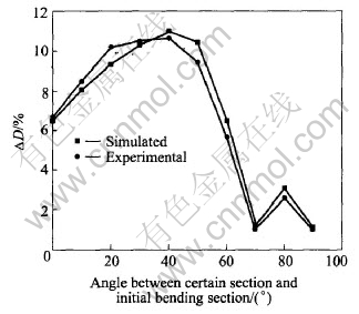
Fig.8 Comparison of length changing ratio of vertical axes of simulation with that of experiment
5 RESULTS AND DISCUSSION
The parameters of dies, tube material, tube geometry and process in simulation are the same as those in experiment. The diameter of mandrel is 35.7mm, 35.8mm and 35.9mm, respectively, the range of mandrel protrusion length is 6��e��12.7mm, 6��e��11.47mm, 6��e��9.87mm, respectively, and mandrel includes one head, two heads and three heads, respectively in the simulation. Cracking and wrinkling are not found in the simulation, which not only verifies that the chosen parameters are reasonable but also provides the basis for further research on cross section distortion and wall thinning.
The vertical axes length changing of every cross section and the outermost wall thinning with different parameters of mandrel are shown in Figs.9-14.
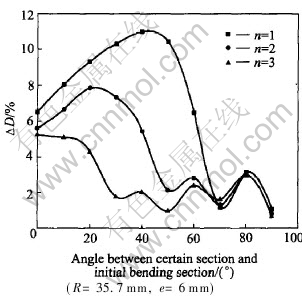
Fig.9 Effect of mandrel head number on changing ratio of vertical axes length
5.1 Effect of number of mandrel heads on cross section quality during thin-walled tube NC bending
The vertical axes length changing ratio of every cross section with different numbers of mandrel heads is shown in Fig.9, where the diameter of mandrel is 35.7mm and the length of mandrel protrusion is 6mm. When the mandrel with one head is used, the section, located at the angle of 40�� with the initial bending section, distorts most seriously and its vertical axes length changing ratio is about 11%. Meanwhile, the distortion of the section, located at the angle of 70�� with the initial bending section, is minimal. When the mandrel with two heads is used, the section, located at the angle of 20�� with the initial bending section, distorts most seriously and the vertical axes length changing ratio is about 7.83%. Meanwhile the distortion of the section, located at the angle of 50�� or 70�� with the initial bending section, is minimal. When the mandrel with three heads is used, the initial bending section distorts most seriously and the vertical axes length changing ratio is about 5.21%. Meanwhile the distortion of the section, located at the angle of 30��, 50�� or 70�� with the initial bending section, is minimal. From the above results, it can be discovered that the number of mandrel heads affects the vertical axes length changing ratio significantly. The maximum value of the vertical axes length decreases greatly with the number of mandrel heads increasing. This is because of the support of mandrel heads, which causes inside wall of tube to undergo the pressure stress from the mandrel head. The pressure stress increases and the area of the pressure stress expands with the number of mandrel heads increasing, which decreases the section distortion of tube bending and causes the section which distorts most seriously closes to the initial bending section. At the same time, there are some sections whose distortion is minimal because mandrel heads causes inside wall of tube bending to undergo the maximum pressure stress at the positions of the mandrel heads.
The outermost wall thinning of every cross section with different number of mandrel heads is shown in Fig.10 under the same conditions. It can be seen that the outermost wall thinning is serious at the middle part and small at the two ends of bending tube in general. The maximum lies on a large range of angle between the middle section and the initial bending section. The maximum of the outermost wall thinning increases and the range of angle contracts with the number of mandrel heads increasing. For sections, located at the angle smaller than 30�� with the initial bending section, the more the number of mandrel heads is, the bigger the outermost wall thinning is. And for sections located at the angle bigger than 50�� with the initial bending section, the more the number of mandrel heads is, the smaller the outermost wall thinning is. It is because that mandrel head changes the state of stress and strain of the tube bending. The more the number of mandrel heads is, the smaller the tangential stress and strain for sections near the bending section are, but the bigger the tangential stress and strain for sections near the initial bending section are.
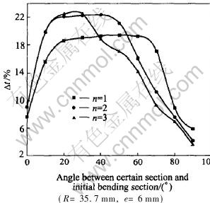
Fig.10 Effect of mandrel head number on thinning ratio of outside wall
Fig.11 Effect of mandrel diameter on changing ratio of vertical axes length
Fig.12 Effect of mandrel diameter on thinning ratio of outermost wall
5.2 Effect of mandrel diameter on cross section quality during thin-walled tube NC bending
The vertical axes length changing ratio of every cross section with different mandrel diameters is shown in Fig.11, where the number of mandrel head is 1, 2, 3, respectively, and the length of mandrel protrusion is 6mm. It can be seen from Fig.11(a) that the bigger mandrel diameter is, the smaller the cross section distortion near the bending section is, but the bigger the cross section distortion in the middle part of bending tube is. This is because sections near the bending section are supported more effectively due to the increasing of mandrel diameter, which causes inside wall of tube to undergo bigger pressure stress from the mandrel. Meanwhile, the resistance force of tube bending increases, which leads to tangential stress increase. Thus the distortion of cross sections, which cannot be effectively supported by mandrel heads, increases. It can be seen from Figs.11(b) and (c) that the bigger mandrel diameter is, the smaller the cross section distortion is. It is because that longer tube wall is supported effectively when the number of mandrel heads is more than 2. The bigger the diameter of mandrel is, the larger the pressure stress acted on inside wall of bending tube is.
The outermost wall thinning of cross section with different mandrel diameters is shown in Fig.12. It can be seen from the figure that the bigger the diameter of mandrel is, the larger the outermost wall thinning of bending tube is. It is because that the resistance force of tube bending increases, which leads to tangential stress increase. But the difference of the outermost wall thinning is small.
5.3 Effect of mandrel protrusion length on cross section quality during thin-walled tube NC bending
The vertical axes length changing ratio of every cross section with different mandrel protrusion length are shown in Fig.13, where the number of mandrel heads is 1, 2, 3, respectively, and the mandrel diameter is 35.7mm. It can be seen in Figs.13(a) and (b) that the cross section distortion of bending tube decreases with the increasing of the mandrel protrusion length. This is because the sections are supported more effectively, which causes inside wall of tube to undergo bigger pressure stress from the mandrel. Meanwhile, the section, with the minimal changing ratio of vertical axes length, has a different angle with the initial bending section. The longer the mandrel protrudes, the smaller the angle becomes. It is because that different mandrel protrusion length changes the position of mandrel heads, which causes the position of the pressure stress maximum to change. It can be seen from Fig.13(c) that the effect of the mandrel protrusion length on vertical axes length changing ratio is more complicated when the number of mandrel heads is 3. It is because that tube wall is supported more effectively, when the effect of the mandrel protrusion length on pressure stress is small. Meanwhile, the resistance force of tube bending increases with the increasing of mandrel protrusion length, which leads to tangential stress increasing. The cross section distorts most seriously at the initial bending section. The fact that the maximum of cross section distortion increases with the increasing of protrusion length shows that the increasing of tangential stress plays a major role.
Fig.13 Effect of mandrel protrusion length on changing ratio of vertical axes length
The outermost wall thinning of cross section with different mandrel protrusion length is shown in Fig.14. It can be seen from the figure that the effect of the mandrel protrusion length on the outermost wall thinning of cross section is complicated but small.
Fig.14 Effect of mandrel protrusion length on thinning ratio of outermost wall
5.4 Selection of reasonable parameters of mandrel during thin-walled tube NC bending
According to the different usage of bending tube, the requirements on section quality are different. In production, except that cross section distortion and wall thinning should satisfy the requirements, the cost of production should be decreased as low as possible. The requirements on section quality is that cross section distortion ratio doesn��t exceed 8% for low-pressure tube and middle-pressure tube used commonly in industry, and 5% for high-pressure tube, meanwhile wall thinning is decreased as small as possible. In order to gain qualified low-pressure and middle-pressure LF2M aluminum alloy bending tube with diameter 38mm, wall thickness 1mm and the radius of bending 57mm, the mandrel with two heads and the diameter 35.7mm should be chosen and the mandrel protrusion length should be set as 6mm according to the above research results. For high-pressure tube, when the mandrel with three heads is chosen, the cross section distortion ratio exceeds 5% a little, but the process of drawing back mandrel can improve the cross section distortion, so it can meet the requirement of quality.
6 CONCLUSIONS
1) According to the principle of NC tube bending, the quality defects which exist during thin-walled tube NC bending are analyzed, which include cracking, wrinkling, cross section distortion and wall thinning; the changing ratio of vertical axes length (��D) and the thinning ratio of outermost wall (��t) are proposed as the parameters to describe the cross section quality of thin-walled tube NC bending.
2) According to the geometrical dimension of tube and dies, the range of mandrel protrusion length is obtained as e1��e��emax, where emax=[KF(]��(2��+D-2t-��)+e2[KF)].
3) The finite element model of thin-walled tube NC bending is established based on the DYNAFORM platform, the key technologies are solved, and the model is verified with experiment.
4) It can be discovered that the number of mandrel heads has a significant effect on vertical axes length changing ratio. The maximum value of vertical axes length changing decreases greatly and the section is closer to the initial bending section with the number of mandrel heads increasing. The outside wall thinning is serious at the middle part and small at the two ends of bending tube in general. The maximum lies on a large range of angle between the middle section and the initial bending section. The maximum of the outermost wall thinning increases and the range of angle contracts with the number of mandrel heads increasing. The effect of the mandrel diameter and protrusion length on the outermost wall thinning of cross section is complicated, but the effect on the outermost wall thinning is small.
5) In order to gain qualified low-pressure and middle-pressure LF2M aluminum alloy bending tube with diameter 38mm, wall thickness 1mm and the radius of bending 57mm, the mandrel with two heads and the diameter 35.7mm should be chosen and the mandrel protrusion length should be set as 6mm according to the above research results. For high-pressure tube, when the mandrel with three heads is chosen, the cross section distortion ratio exceeds 5% a little, but the process of drawing back mandrel can improve the cross section distortion, so it can meet the requirements of quality.
REFERENCES
[1]YANG He, LIN Yan, SUN Zhi-chao. Review of advanced plastic processing technology and tube forming facing 21st century [A]. Symposium of 2nd China Science Association annual conference [C]. Beijing: Science and Technology Press, 2000. 745-746.(in Chinese)
[2]YANG H, ZHAN M, LIU Y L. Some advanced plastic processing technologies and their numerical simulation [J]. Journal of Materials Processing Technology, 2004, 151: 63-69.
[3]YANG He, LIN Yan. Wrinkling analysis for forming limit of tube bending processes [J]. Journal of Materials Processing Technology, 2004, 152: 363-369.
[4]ZHAN M, YANG H, JIANG Z Q. A study on a 3D FE simulation method of the NC bending process of thin-walled tube [J]. Journal of Materials Processing Technology, 2002, 129: 273-276.
[5]LI H, YANG H, ZHAN M, et al. Wrinkling limit based on FEM virtual experiment during NC bending process of thin-walled tube [J]. Materials Science Forum, 2004, 471-472: 498-502.
[6]Al-Qureshi H A. Elastic-plastic analysis of tube bending [J]. Journal of Machine Tools & Manufacture, 1999, 39: 87-104.
[7]Li H Z, Fagerson R. A method of adaptive control of rotary-draw thin-walled tube bending with springback compensation [J]. Transaction of NAMRI/SME, 1994, ����: 25-28.
[8]Stelson K A. The deformation of shape [J]. Journal of Engineering Materials and Technology, 2000, 121: 320-326.
[9]Tang N C. Plastic-deformation analysis in tube bending [J]. International Journal of Pressure Vessels and Piping, 2000, 77: 751-759.
[10]Trana K. Finite element simulation of the tube hydroforming process��bending, preforming and hydroforming [J]. Journal of Materials Processing Technology, 2002, 127: 401-408.
[11]Jin Z, Luo S, Fang X D. KBS-aided design of tube bending processes [J]. Engineering Applications of Artificial Intelligence, 2001, 14: 599-606.
[12]Kyriakides S, Corona E, Miller J E. Effect of yield surface evolution on bending induced cross sectional deformation of thin-walled sections [J]. International Journal of Plasticity, 2004, 20: 607-618.
[13]Miller J E, Kyriakides S. Three-dimensional effects of the bend-stretch forming of aluminum tubes [J]. International Journal of Mechanical Sciences, 2003, 45: 115-140.
[14]Miller J E, Kyriakides S, Bastard A H. On bend-stretch forming of aluminum extruded tubes(��): experiments [J]. International Journal of Mechanical Sciences, 2001, 43: 1283-1317.
[15]Miller J E, Kyriakides S, Corona E. On bend-stretch forming of aluminum extruded tubes(��): analysis [J]. International Journal of Mechanical Sciences, 2001, 43: 1319-1338.
[16]ZHAN Mei, YANG He, LI Zhen. Finite element analysis of influence of mandrel on thinning ratio of wall in NC tube bending [J]. Mechanical Science and Technology, 2004, 23(6): 669-670.(in Chinese)
[17]WANG Guang-xiang, YANG He, LI He. Experimental study of the influence of processing parameters on forming quality of thin-walled NC bending tube [J]. Mechanical Science and Technology, 2005, 24(8): 995-998.(in Chinese)
(Edited by LONG YUAN Sai-qian)
Foundation item: Project(50225518) supported by the National Science Foundation of China for Distinguished Young Scholars; Projects(50175092; 59975076) supported by the National Natural Science Foundation of China; Project supported by the Teaching and Research Award Program for Outstanding Young Teachers in Higher Education Institutions of MOE, China; Project(04H53057) supported by the Aeronautical Science Foundation of China; Project(20020699002) supported by the Specialized Research Fund for the Doctoral Program of Higher Education and project supported by the Graduate Starting Seed Fund of Northwestern Polytechnical University
Received date: 2005-03-07; Accepted date: 2005-06-02
Correspondence: YANG He, Professor; Tel/Fax: +86-29-88495632; E-mail: yanghe@nwpu.edu.cn
