
J. Cent. South Univ. (2012) 19: 117-127
DOI: 10.1007/s11771-012-0980-y![]()
Robust tracking control for micro machine tools with load uncertainties
FAN Shi-xun(������), FAN Da-peng(������), HONG Hua-jie(�黪��), ZHANG Zhi-yong(������)
College of Mechatronic Engineering and Automation,
National University of Defense Technology, Changsha 410073, China
? Central South University Press and Springer-Verlag Berlin Heidelberg 2012
Abstract:
The quality of the micro-mechanical machining outcome depends significantly on the tracking performance of the miniaturized linear motor drive precision stage. The tracking behavior of a direct drive design is prone to uncertainties such as model parameter variations and disturbances. Robust optimal tracking controller design for this kind of precision stages with mass and damping ratio uncertainties was researched. The mass and damping ratio uncertainties were modeled as the structured parametric uncertainty model. An identification method for obtaining the parametric uncertainties was developed by using unbiased least square technique. The instantaneous frequency bandwidth of the external disturbance signals was analyzed by using short time Fourier transform technique. A two loop tracking control strategy that combines the ��-synthesis and the disturbance observer (DOB) techniques was proposed. The ��-synthesis technique was used to design robust optimal controllers based on structured uncertainty models. By complementing the �� controller, the DOB was applied to further improving the disturbance rejection performance. To evaluate the positioning performance of the proposed control strategy, the comparative experiments were conducted on a prototype micro milling machine among four control schemes: the proposed two-loop tracking control, the single loop �� control, the PID control and the PID with DOB control. The disturbance rejection performances, the root mean square (RMS) tracking errors and the performance robustness of different control schemes were studied. The results reveal that the proposed control scheme has the best positioning performance. It reduces the maximal errors caused by disturbance forces such as friction force by 60% and the RMS errors by 63.4% compared with the PID control. Compared to PID with DOB control, it reduces the RMS errors by 29.6%.
Key words:
1 Introduction
Micro-mechanical machining is an important fabrication method for creating miniature devices and components that range from tens of micro meters to a few millimeters in size [1-3]. The quality of the micro- mechanical machining outcome depends significantly on the tracking performance of the miniaturized linear motor drive precision stage (i.e. XY table). It is well known that the tracking behavior of a direct drive design is prone to uncertainties such as model parameter variations and disturbances. Therefore, much attention must be paid to the robustness against such uncertainties in controller design.
Some efforts have been made toward advanced robust control of linear motor drive systems. Adaptive robust control (ARC) presented in Refs. [4-5] achieves a guaranteed tracking accuracy by taking into account the effect of both model uncertainties and external disturbances. Various neural network based adaptive controllers were proposed in Refs. [6-8]. Fuzzy logic and learning law were combined with neural networks to deal with the effect of nonlinear disturbances and model parameter variations. These algorithms mainly focused on the adaptive compensation of the disturbances and the adaptation problems of model parameters, but not on tracking behavior optimization. PID like feedback control structure is usually applied in these algorithms to designing the dynamics of the tracking errors, which is not optimal in the view of optimal control.
Robust optimal control focused on optimizing the control performance of the control systems with the existence of the model uncertainties. It is an efficient method for designing precision linear motor servo systems [9-14]. One of the main advantages of robust optimal control is that it can simultaneously optimize more dynamic properties of linear motor feed drive systems as required by the machining processes. Special requirements such as maximizing servo stiffness to avoid machining chatter, maximizing servo bandwidth to obtain faster response ability and mapping closed loop poles optimally to increase the damping ratio of transient dynamics, can be robustly guaranteed by using robust optimal control. In addition to the former application researches, it was reported in Ref. [15] that combining the disturbance observer (DOB) with two-DOF H�� controller could simultaneously achieve better variant friction force cancellation performance and sufficient robustness in terms of stability and tracking performance.
Most of the previous researches on the applications of robust optimal control to machine tool servo systems used unstructured dynamic uncertainty (additive or multiplicative uncertainty), but not parametric uncertainty to represent the mass uncertainty model of the system, and applied the conventional H�� loop shaping synthesis method to designing optimal robust controllers. In robust control, reducing the size of the uncertainties usually leads to better performance [16-18]. The uncertain models represented by structured parametric uncertainties have smaller size in uncertainty than that represented by unstructured dynamic uncertainties. Therefore, if parametric uncertainty model is utilized in robust controller design, the performance is expected to be improved.
This work focused on applying ��-synthesis technique to designing robust optimal tracking controllers for micro milling machine tools with mass and damping ratio. The main contributions are as follows. The parametric uncertainty model of the miniaturized linear motor drive of the micro milling machine was obtained. An identification method for parametric uncertainty models was developed. The instantaneous frequency bandwidth of the external disturbance signals was analyzed. A two loop tracking controller was designed. A disturbance observer inner loop was employed to reduce the effects of the variant disturbances such as the friction force and the cutting force. An outer loop controller was designed with the consideration of optimizing both the robust disturbance rejection performance and the robust tracking performance. A general design procedure of the controller is demonstrated. Comparative experiments among the controller, the controller with a DOB, the PID controller and the PID controller with a DOB were conducted on a prototype micro milling machine.
2 Uncertainty model of miniaturized linear motor drive
The experimental setup of a prototype micro milling machine is shown in Fig. 1. The miniaturized precision stage of the prototype micro milling machine is Aerotech XY linear drive ALS10020. Figure 2 shows the dynamic model of one axis of the precision stage. Fm represents motor force. Fd is the disturbance force including the nonlinear friction force and the cutting force. The corresponding state space model can be written as

![]()
where the state vector x consists of the stage position x1 and velocity x2, u denotes the control input, d denotes the equivalent disturbance that has the same unit as u. The scalars Ka and Kt are the amplifier gain and the motor force constant, respectively. They are treated as constant values, and their uncertainties are merged with the uncertainties of m and b. ![]() and
and ![]() are uncertain matrices with parametric uncertainties, due to bounded uncertain parameters m and b, while C is the constant output matrix.
are uncertain matrices with parametric uncertainties, due to bounded uncertain parameters m and b, while C is the constant output matrix.
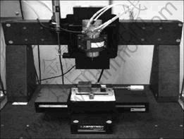
Fig. 1 Experimental setup of prototype micro milling machine
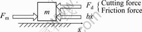
Fig. 2 Dynamic model of one axis of a miniaturized precision stage
The state space model has two types of model uncertainties which are parametric uncertainty and external uncertain disturbance forces. To serve for robust control design, the characteristics of the above model uncertainties are analyzed. An identification method is given to identify the parametric uncertainty model. The instantaneous frequency characteristics of the external uncertain disturbance forces are analyzed.
2.1 Analysis and identification of parametric uncertainties
Two uncertain parameters m and b are included in the state space model. m is an unknown parameter related to which kind of manufacturing will be done and which kind of spindles, clipping devices and workpieces will be mounted on the feed drives. The feed drives of the micro milling machine have small size. The masses of them are usually small. The spindles, clipping devices and workpieces have relatively large masses whose typical values are from 1 to 2 times of the feed drives. b is an uncertain parameter which is only known approximately by identification and may vary during operations depending on the work region, mass of the load and lubrication condition, but its varying range is small. So, the parametric uncertainties for the micro- machining machine tool feed drive can be represented as
![]()
where m0 and b0 are the nominal values of the model, which can be calculated as
![]()
wm and wb are the weights of the uncertainties with the definitions of
![]()
mmax, mmin, bmax and bmin are the boundaries of m and b, respectively. ��m and ��b are real uncertain numbers with the value between -1 and 1.
The parametric uncertainty model of the miniaturized linear motor drive precision stage is given by Eqs. -. There are four parameters needed to be identified in the model. They are mmax, mmin, bmax and bmin. State function Eq. includes a nonlinear disturbance input d. In parameter identification stage, the main components of d is the friction force. The model is no longer an ideal linear model. The parameters cannot be accurately identified by using traditional frequency swept test. It is proposed here to apply a time domain unbiased least squares (LS) technique [19] to solving the identification problem. By representing the friction force with the Coulomb friction model, this technique can give precise identifications of m and b, as well as Coulomb friction coefficients simultaneously.
Now, the derivation of the unbiased LS technique is briefly introduced as follows.
The discretized transfer function can be derived from the state space model Eq. as

where V(k) is the velocity time series of the worktable. Assuming that d(k) is the combination of Coulomb friction and random disturbance forces, and the Coulomb friction has different values related to different directions of the velocity, it becomes

Substituting Eq. into Eq. , a difference equation can be obtained as
![]()
![]()
The parameters that need to be identified are pd, Kd, ![]() and
and ![]() . Define the following equations:
. Define the following equations:
![]()

![]()
where �� is the parameter vector. �� and y are experimental data. According to least squares theory, the estimation of �� can be calculated by
![]()
Once ![]() is obtained,
is obtained, ![]() and
and ![]() , which are the estimations of b and m, respectively, can be solved from Eq. .
, which are the estimations of b and m, respectively, can be solved from Eq. .
The procedures to identify the parametric uncertainty model are as follows.
1) Choose test points with different load masses according to the working conditions of the machine. For example, the test points can be the work table without any load, the work table with the largest load, and two or three points within this range;
2) Excite the system with wideband testing signal, and acquire the response;
3) A parameter vector set ![]() corresponding to different test points, can be identified by using Eqs. and ;
corresponding to different test points, can be identified by using Eqs. and ;
4) Search for ![]() ,
, ![]() ,
, ![]() and
and ![]() from the identified parameter vector set;
from the identified parameter vector set;
5) Calculate the average values of ![]() and
and ![]() .
.
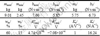
The parameters of the prototype micro milling machine shown in Fig. 1 are identified by using the proposed method. The results are given in Table 1.
Table 1 Identified parameters of x axis of prototype micro milling machine tool
2.2 Instantaneous frequency characteristics of external disturbances
The main components of the time-variant external disturbance forces exerting on miniaturized linear motor precision stages are nonlinear friction force and cutting force. The complicated physical natures of friction and cutting forces are not concerned. The instantaneous bandwidth of the time-variant external disturbance signals is analyzed here from the standpoint of control. By observing tracking error plots of a closed loop feed drive servo system, it can be concluded that the effect of slow varying disturbances can easily be eliminated by increasing the low-frequency gain of a feedback controller, but instantaneous fast varying disturbances that usually have a wide instantaneous bandwidth can cause large peak errors more complicated to be handled. To eliminate the effect of fast varying disturbances, only considering the low-frequency gain of the control loop is not enough. The sensitivity function from the disturbance input to the error out of the control loop needs to be carefully designed based on the instantaneous frequency characteristics of the disturbance signals. More specifically, the instantaneous frequency bandwidth of the disturbance signals is important for both selecting the bandwidth of the DOB and designing the weighting functions for ��-synthesis.
2.2.1 Instantaneous bandwidth of friction force
The major characteristics of the friction can be represented by Stribeck friction model [20]. The result is shown in Fig. 3. The coefficients TSta and TCoul are station and Coulomb friction constants, respectively.
The friction force can be represented as a nonlinear function of relative velocity, relative position and time. That is to say, TSta and TCoul in Fig. 3 are both time varying coefficients depending on position and time. Their time-variant features can be divided into two regimes.
1) In high-speed regime, the relative velocity holds its direction, and the friction force shows two types of time dependent variability. The contact surfaces of guide ways of worktables are nonconformal, which causes position-dependent variations in TSta and TCoul. The changing rate of each coefficient is related to the absolute value of relative velocity. Since their amplitudes are usually very small, this type of time variability can be omitted. As working conditions vary, the lubrication conditions vary, causing the other type variations in TSta and TCoul. This type of time-dependent variability is very slow with small amplitude as well. Therefore, it is sensible to treat the friction force as a constant disturbance in this regime.
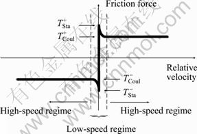
Fig. 3 Stribeck friction model
2) In slow-speed regime, friction force is governed by Stribeck curve. This regime is divided into two sections: exponentially varying section and stepping section. The energy spectrum of the friction signal in exponentially varying section mainly concentrates within low-frequency band, whereas the friction signal in stepping section has much wider instantaneous bandwidth. That is to say, the instantaneous bandwidth of the friction signal in this regime is decided by the stepping section.
According to the previous analysis, friction force is a kind of non-stationary signal. The stepping section of the friction force signal has a relatively high instantaneous frequency bandwidth. It is the principle factor that deteriorates the servo system, causing spikes in tracking errors. Its instantaneous bandwidth can be obtained by using short-time Fourier transform (STFT). The time constant of a closed loop feed drive system is usually around dozens of milliseconds. A Gaussian window with the data length of 40 ms is used in STFT. The center of the window is selected at the stepping point. The data section of 20 ms before and 20 ms after the stepping point is intercepted and analyzed. The result is regarded as the instantaneous frequency characteristic of the stepping section. The STFT result is shown in Fig. 4. Based on the local data section 20 ms before and 20 ms after the stepping point, the �C3 dB instantaneous bandwidth of the stepping friction is around 30 Hz.
2.2.2 Bandwidth of cutting forces
Micro milling machine centers can implement three kinds of machining: turning, milling and electric discharge machining (EDM). Turning operation is a continuous cutting process. Its cutting force can be treated as a constant disturbance. The cutting force of EDM is usually very tiny, hence it can be omitted. Milling operation involves interrupted cutting. Its cutting force is a periodical force. The frequency of it is decided by the number of tool teeth and the speed of spindle. For micro milling, the number of tool teeth is usually 2, and the speed of spindle is usually from 10 000 to 20 000 r/min. The corresponding frequency of cutting force is usually 300-700 Hz. It is much higher than the servo bandwidth of worktable. Only low frequency component within 100 Hz of cutting force will disturb the servo system. Figure 5(a) shows the waveform of cutting force during a typical micro milling operation in one direction. The spindle speed is 20 000 r/min, the feed rate is 400 mm/min, and the depth of cut is 50 ��m. The corresponding magnitude-frequency characteristics are shown in Fig. 5(b). It illustrates that the interrupted cutting frequency is 666.5 Hz. The bandwidth of low frequency spectrum component is around 29.8 Hz.
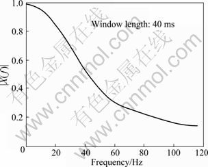
Fig. 4 Instantaneous frequency characteristic of stepping section friction signal with Gaussian window
3 Robust tracking control design
The DOB and the ��-synthesis techniques were combined to design a high performance robust tracking control law for the micro machine tool drive with parametric uncertainties defined by Eqs. -. The DOB was used to counteract low frequency nonlinear disturbances including friction force and cutting force to enhance low speed motion smoothness. The ��-synthesis technique was utilized to deal with this structured parametric uncertainty to guarantee the robust performance of the closed loop control. The control structure is shown in Fig. 6.
3.1 Disturbance observer design
The DOB provides a way of rejecting disturbances which cannot be accurately modeled in advance [21]. The structure of the DOB is shown in Fig. 6, where ![]() is the inverse of the nominal model Gn. By submitting the nominal parameters calculated with Eq. into Eq. , Gn can be solved with the following equation:
is the inverse of the nominal model Gn. By submitting the nominal parameters calculated with Eq. into Eq. , Gn can be solved with the following equation:
![]()
where ![]() and
and ![]() are nominal state matrix and nominal input matrix, respectively. After
are nominal state matrix and nominal input matrix, respectively. After ![]() is obtained, the key procedure is to select the filter Q(s). The procedure includes two steps: filter structure selection and filter bandwidth selection. It was shown by other researchers that a third-order low-pass filter often provides good performance. It can be written as
is obtained, the key procedure is to select the filter Q(s). The procedure includes two steps: filter structure selection and filter bandwidth selection. It was shown by other researchers that a third-order low-pass filter often provides good performance. It can be written as
![]()
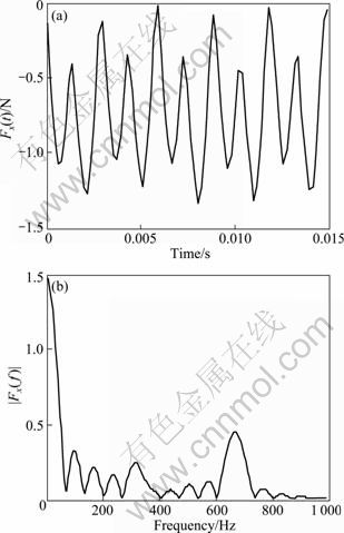
Fig. 5 Experimental micro milling cutting force with spindle speed of 20 000 r/min: (a) Time domain waveform; (b) Magnitude-frequency characteristic plot
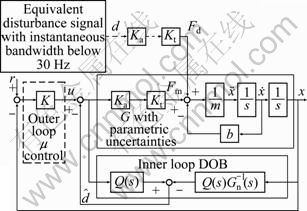
Fig. 6 Block diagram of robust tracking control strategy
The bandwidth of the Q filter can be selected according to the effective bandwidth of the disturbances. The external disturbances of the miniaturized linear motor drive precision stage have been analyzed in Section 2. The main conclusions are as follows.
1) The instantaneous bandwidth of the friction disturbance signal is around 30 Hz.
2) The bandwidth of low frequency spectrum component of cutting force is below 30 Hz.
Based on these conclusions, the -3dB cut-off frequency of the Q filter was selected as 40 Hz. The corresponding time constant �� was 0.004.
3.2 Robust tracking controller design with ��-synthesis
The control purpose of the outer loop position feedback controller is to make the stage position y precisely track the reference signal r in the presence of disturbance d by using a bounded control effort u. This is equivalent to designing a controller to make the tracking error e insensitive to both the reference input r and the disturbance d in an interested frequency region with limited control effort u.
Figure 7 shows the block diagram of the closed loop used for robust tracking controller synthesis. The plant G is the parametric uncertain model represented by Eqs. -. Wp is used to shape the two sensitivity functions from r to e and d to e together, while Wu is used to limit the control effort for tracking and disturbance rejection. The selection of Wu and Wp can trade off the desired tracking performance and the control effort.
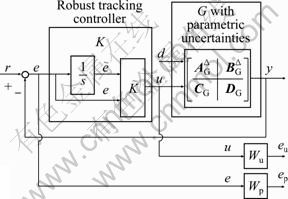
Fig. 7 Block diagram of closed loop
Traditional machine tool servo control applications have verified that an integrator should be included in the control loop to eliminate the steady state error. The idea of ��-synthesis is to find a controller from a controller set which includes all proper rational internally-stabilizing controllers governing the plant to fulfill the weighting function Wu and We. The result from ��-synthesis will not include integrator. For this reason, an integrator is added in the input path of the controller. The inner structure of the robust tracking controller K is illustrated in Fig. 7. The one-input and one-output controller K is substituted for an integrator plus a two-inputs and one-output controller ![]() . The existence of the integrator can guarantee steady state error converging to zero, while the advantage of the second input of
. The existence of the integrator can guarantee steady state error converging to zero, while the advantage of the second input of ![]() is to make the control structure more general to include more controller candidates for ��-synthesis optimization. The controller design procedures are as follows.
is to make the control structure more general to include more controller candidates for ��-synthesis optimization. The controller design procedures are as follows.
1) Derive the standard mixed sensitivity H�� optimization problem from the configuration of the control loop (see Fig. 7).
2) Solve the mixed sensitivity H�� optimization problem with ��-synthesis to obtain a high order controller ![]() . It can be implemented by using the DK iteration ��dksyn�� of the robust toolbox of the MATLAB.
. It can be implemented by using the DK iteration ��dksyn�� of the robust toolbox of the MATLAB.
3) Reduce the order of ![]() to obtain
to obtain ![]() . It can be implemented by using the function ��reduce�� of the robust toolbox of the MATLAB.
. It can be implemented by using the function ��reduce�� of the robust toolbox of the MATLAB.
4) Combine ![]() with the integrator to get K.
with the integrator to get K.
The following controller transformations are needed to implement the fourth step.
The state space form of controller ![]() is
is

The state space model of an integrator is
![]()
Combining the state variables of Eq. and Eq. , the tracking controller K is obtained as

For example, the outer loop position feedback controller for x axis of the prototype micro milling machine tool is designed. The parameters of the plant are given in Table 1. Wu is selected as 0.001, which means that the largest controller gain is less than 60 dB. Corresponding to this limitation, Wp is tuned by trial and error to achieve the best achievable performance. By tuning Wp, the following two items are expected to be optimized: 1) Ensure the closed loop servo bandwidth over 50 Hz. 2) Ensure the disturbance rejection performance within the frequency range below 30 Hz less than -20 dB.
The resultant Wp here is
![]()
Its magnitude-frequency characteristic is shown in Fig.8 with dashed line.
Following the procedures 1) to 4), an eighth-order �� controller K is obtained. The sensitivity functions of the outer loop compensated by the controller K are shown in Fig.8. In(1) and In(2) denote reference signal r and the disturbance d, respectively. Out(1) denotes tracking error e, and Out(2) denotes control effort u. Figure 8 shows that for different model uncertainties, the controller can guarantee that the singular values of both sensitivity functions Sr��e and Sd��e are less than weighting function Wp. The controller gains for both r and d are less than 60 dB. These indicate that the controller K robustly guarantees the control performances defined by the weighting functions Wp and Wu with the existence of model uncertainties.
4 Experimental results
The experimental setup is shown in Fig.1. The precision stage is Aerotech XY linear drive ALS10020. The position sensor is linear scale with the resolution of 1 ��m. The total mass of the moving part is around 2.5 kg.
The amplifier is Aerotech BA10-40 operating in the current control mode. The control unit is a dSPACE digital controller 1103 equipped with 16 bit ADCs and DACs and 24 bit incremental encoder inputs. The sampling period is selected to be 0.1 ms.
Two trajectories, low speed and high speed lines, are used to evaluate the positioning performance of the controllers. Positioning performance evaluation is based on the maximal and the root mean square (RMS) tracking errors along the two specified trajectories. Two trajectory profiles are shown in Fig. 9. Considering the requirement of the micro-machining process and the test bed limits, the following values are chosen in the trajectory generation. Both of the two trajectories have the strokes of 100 mm and the accelerations of 200 mm/s2. The low-speed line trajectory has cruise speed at 10 mm/s and the high-speed one has 30 mm/s.
For performance comparison, a PID controller is designed to have similar closed-loop bandwidth around 50 Hz for the nominal plant (with 3 kg mass load). If a higher bandwidth is selected, the closed loop system for the plant with 9 kg mass load would easily become unstable. The transfer function of the PID controller is
![]()

Fig. 8 Sensitivity functions of perturbed closed-loop systems: (a) For In(1) and Out(1); (b) For In(2) and Out(1); (c) For In(1) and Out(2); (d) For In(2) and Out(2)

Fig. 9 Desired trajectories
The trajectory tracking performances of the PID controller, the �� controller, the PID controller with a DOB and the �� controller with a DOB are studied under low speed and high speed line commands with different mass loads. The corresponding tracking errors in these different controllers under low-speed command with different loads are shown in Fig. 10. The maximal tracking errors are the spikes in the errors caused by the nonlinear friction, when the direction of the motion reverses. The experimental results show that the case of the PID without a DOB inner loop has large maximal tracking errors. The maximal tracking errors for this case range from 20 to 40 ��m. The �� controller complemented by an internal-loop DOB has the best tracking accuracy. The maximal tracking error is within 10 ��m. The RMS and the maximal tracking error of these controllers are shown in Fig. 11. The RMS tracking error curve of the �� with DOB controller is in the bottom of the plot, and its values range from 0.73 to 1.49 ��m. PID controller has the largest RMS tracking error that ranges from 2.18 to 2.71 ��m. Compared with PID controller, the proposed controller reduces the maximal error by 60% and the RMS error by 63.4%. Compared with the PID controller with a DOB, the �� controller with a DOB reduces the RMS error by 29.6%. Similar results can be observed for the high-speed command from Fig. 12 and Fig. 13.
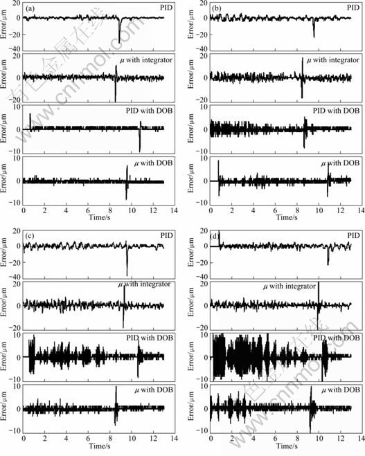
Fig. 10 Low speed trajectory tracking errors with different mass loads: (a) 3 kg; (b) 6 kg; (c) 7.5 kg; (d) 9 kg
The robustness of the controlled system was studied under the working conditions with different mass loads. The PID controller was designed based on the nominal model with the mass load of 3 kg. Figs. 10(a)-(d) show that the oscillations occur in the tracking errors as the mass load increases. When the mass of the load is increased to 9 kg, the PID with DOB controller shows serious oscillations with very small damping that can hardly converge. This indicates that the stability margin has been degraded. Although the oscillations also occur in the case that the �� with DOB controller is used, the amplitudes of the oscillations are much smaller and can converge quickly. This indicates that the proposed controller can effectively hold proper dynamic damping and sufficient stability margin. The proposed controller has better performance robustness than the other controllers under system parameter variation.
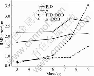
Fig.11 RMS errors of low speed trajectory tracking
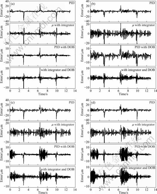
Fig. 12 High speed trajectory tracking errors with different mass loads: (a) 3 kg; (b) 6 kg; (c) 7.5 kg; (d) 9 kg
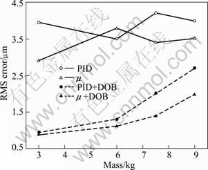
Fig. 13 RMS errors of high speed trajectory tracking varying with mass load
5 Conclusions
1) By intercepting local friction data section using a Gaussian window with a length of 40 ms and a center at the stepping point, and solving STFT of the data section, it is shown that �C3 dB instantaneous bandwidth of the stepping friction is around 30 Hz.
2) For micro milling, the number of teeth is 2, and the speed of the spindle is from 10 000 to 20 000 r/min. Considering the above conditions, the bandwidth of the low frequency component of the cutting force is below 30 Hz.
3) To design servo controller for micro-milling machine by using ��-synthesis complemented with DOB technique can achieve superior disturbance rejection performance over PID and PID with DOB control strategies. Proposed �� controller with a DOB inner loop control strategy can reduce the maximal errors caused by disturbance forces such as friction force by 60% and the RMS errors by 63.4% compared with PID controller. Compared with PID with DOB control scheme, the �� with a DOB inner loop control scheme reduces the RMS errors by 29.6%.
4) The �� controller with a DOB inner loop control scheme has better performance robustness than �� controller without DOB, PID with and without DOB.
5) The drawback of the current work is that the parameters of the DOB inner loop need to be tuned experimentally to achieve both good disturbance rejection performance and robust stability of the closed loop control system. If a systematic design procedure that mathematically guarantees the robustness stability of the two loop controller is developed, the parameter tuning procedure can be dramatically simplified. This research will be conducted in the future.
Acknowledgements
The authors would like to thank Prof. Y. ALTINTAS of the Manufacturing Automation Laboratory, the Department of Mechanical Engineering, the University of British Columbia (UBC), for providing access to the micro-milling machine setup. The work was supported by the Canada Foundation for Innovation (CFI).
References
[1] CHAE J, PARK S S, FREIHEIT T. Investigation of micro-cutting operations [J]. International Journal of Machine Tools & Manufacture, 2006, 46: 313-332.
[2] HUO De-hong, CHENG Kai, WARDLE F. A holistic integrated dynamic design and modelling approach applied to the development of ultraprecision micro-milling machines [J]. International Journal of Machine Tools & Manufacture, 2010, 50: 335-343.
[3] AFAZOV S M, RATCHEV S M, SEGAL J. Modelling and simulation of micro-milling cutting forces [J]. Journal of Materials Processing Technology, 2010, 210: 2154-2163.
[4] XU L, YAO Bin. Adaptive robust precision motion control of linear motorswith negligible electrical dynamics: Theory and experiments [J]. IEEE/ASME Transactions on Mechatronics, 2001, 6(4): 444-452.
[5] LU Lu, YAO Bin, WANG Qing-feng, CHEN Zheng. Adaptive robust control of linear motors with dynamic friction compensation using modified LuGre model [J]. Automatica, 2009, 45: 2890-2896.
[6] MAKKAR C, HU G, SAWYER W G, DIXON W E. Lyapunov-based tracking control in the presence of uncertain nonlinear parameterizable friction [J]. IEEE Transactions on Automatic Control, 2007, 52(10): 1994-1998.
[7] HASANIEN H M, MUYEEN S M, TAMURA J. Speed control of permanent magnet excitation transverse flux linear motor by using adaptive neuro-fuzzy controller [J]. Energy Conversion and Management, 2010, 51: 2672-2768.
[8] NASO D, CUPERTINO F, TURCHIANO B. Precise position control of tubular linear motors with neural networks and composite learning [J]. Control Engineering Practice, 2010, 18: 515-522.
[9] ALTER D M, TSAO T C. Stability of turning processes with actively controlled linear motorfeed drives [J]. ASME Journal of Engineering for Industry-Transactions, 1994, 116: 298-307.
[10] ALTER D M, TSAO T C. Control of linear motors for machine tool feed drives: Design and implementation of H-infinity optimal feedback control [J]. ASME Journal of Dynamic Systems Measurement and Control, 1996, 118: 649-656.
[11] Van den BRAEMBUSSCHE P, SWEVERS J, van BRUSSEL H. Design and experimental validation of robust controllers for machine tool drives with linear motor [J]. Mechatronics, 2001, 11: 545-562.
[12] CHOI C, TSAO TSU-CHIN. Control of linear motor machine tool feed drives for end milling: robust MIMO approach [J]. Mechatronics, 2005, 15: 1207-1224.
[13] SHEN Bin-Hong, TSAI MI-Ching. Robust dynamic stiffness design of linear servomotor drives [J]. Control Engineering Practice, 2006, 14: 1325-1336.
[14] ZHENG Kai, LEE A H, BENTSMAN J, KREIN P T. High performance robust linear controller synthesis for an induction motor using a multi-obrective hybrid control strategy [J]. Nonlinear Analysis, 2006, 65: 2061-2081.
[15] YEN Ping-lang. A two-loop robust controller for compensation of the variant friction force in an over-constrained parallel kinematic machine [J]. International Journal of Machine Tools & Manufacture, 2008, 48: 1354-1365.
[16] AZADI YAZDI E, NAGAMUNE R. Multiple robust H-infinity controller design using the nonsmooth optimization method [J]. International Journal of Robust and Nonlinear Control, 2010, 20(11): 1197-1312.
[17] GU D W, PETKOV P HR, KONSTANTINOV M M. Robust control design with MATLAB [M]. Lodon: Springer Press, 2005: 71-74.
[18] DOYLE J, FRANCIS B, TANNENBAUM A. Feedback control theory [M]. New York: McMillam, 1992: 195-204.
[19] ERKORKMAZ K, ALTINTAS Y. High speed CNC system design. Part II: modeling and identification of feed drives [J]. International Journal of Machine Tools & Manufacture, 2001, 41: 1487-1509.
[20] MARTON L, LANTOS B. Control of mechanical systems with Stribeck friction and backlash [J]. System & Control Letters, 2009, 58: 141-147.
[21] LEE H S, TOMIZUKA M. Robust motion controller design for high-accuracy positioning systems [J]. IEEE Transactions on Industrial Electronics, 1996, 43: 48-55.
(Edited by YANG Bing)
Foundation item: Project(50875257) supported by the National Natural Science Foundation of China
Received date: 2011-02-23; Accepted date: 2011-09-13
Corresponding author: FAN Da-peng, Professor, PhD; Tel: +86-731-84576388; E-mail: fdp@nudt.edu.cn
Abstract: The quality of the micro-mechanical machining outcome depends significantly on the tracking performance of the miniaturized linear motor drive precision stage. The tracking behavior of a direct drive design is prone to uncertainties such as model parameter variations and disturbances. Robust optimal tracking controller design for this kind of precision stages with mass and damping ratio uncertainties was researched. The mass and damping ratio uncertainties were modeled as the structured parametric uncertainty model. An identification method for obtaining the parametric uncertainties was developed by using unbiased least square technique. The instantaneous frequency bandwidth of the external disturbance signals was analyzed by using short time Fourier transform technique. A two loop tracking control strategy that combines the ��-synthesis and the disturbance observer (DOB) techniques was proposed. The ��-synthesis technique was used to design robust optimal controllers based on structured uncertainty models. By complementing the �� controller, the DOB was applied to further improving the disturbance rejection performance. To evaluate the positioning performance of the proposed control strategy, the comparative experiments were conducted on a prototype micro milling machine among four control schemes: the proposed two-loop tracking control, the single loop �� control, the PID control and the PID with DOB control. The disturbance rejection performances, the root mean square (RMS) tracking errors and the performance robustness of different control schemes were studied. The results reveal that the proposed control scheme has the best positioning performance. It reduces the maximal errors caused by disturbance forces such as friction force by 60% and the RMS errors by 63.4% compared with the PID control. Compared to PID with DOB control, it reduces the RMS errors by 29.6%.
