

Special-shaped tube drawing forming and conformal optimization of die cavity
QI Hong-yuan(���Ԫ), ZHU Heng-jun(����)
School of Mechanical and Electric Control Engineering,Beijing Jiaotong University, Beijing 100044, China
Received 20 April 2006; accepted 30 June 2006
Abstract:
Aiming at the issues in quick processing and modeling design of drawing special-shaped tube die, by Conformal Mapping Theory and the numerical trigonometry method of interpolation between odd points and even points, the conformal mapping function is obtained. As the result, three-dimension drawing forming were converted into that of two-dimension problems, and the plastic stream function was analyzed, die cavity modeling and its optimized function were set up. Combining with modern processing technology, NC program and CAM of die cavity can be realized. Taking the drawing forming of hexagon tube with arc radii r and ellipse-shaped tube as instances, the drawing die cavity optimization of special-shaped tube was achieved, as well as, the changing principle of wall thickness was analyzed.
Key words:
drawing; special-shaped tube; forming; Conformal Mapping; optimization;
1 Introduction
Special-shaped tube drawing is called as the forming process of non-round tube obtained from metal tube of forming die region causing the plastic forming under drawing forces. In the process of drawing, there exists tangent metal plastic flow, so the drawing mechan- ism shows as non-axi-symmetrical three- dimension problem. E.g. the varied wall thickness can not be predicted by two-dimension forming theory[1]. Due to the restriction of mathematics, related research fruits are hardly reported, so that the generalized three-dimension analysis theory is not set up systematically yet[2, 3]. As the result, it is hard to realize the drawing analysis and die quick processing.
Nowadays, by Conformal Mapping theory, using the mapping function which can transfer the given typical region into simple region, the complicated region can be changed into simple region[4, 5], thus, some engineering problems gets solved. Conformal Mapping theory has been applied in mechanical vibration[6], elec- tromagnetics[7], hydromechanics[8] and plastic process- ing fields[9]. Analyzing the vibration of simple- supported elastic plates with multi-concentrated mass, the complicated plates region and its vibrating function can be described by unit dish region, hence, its fundam- ental frequency can be determined[10].
At present, the general-used processing technology of special-shaped drawing die cavity includes electrical discharge machining, electrolytic girding and NC milling machine technology ect. However, by the existed numerical modeling methods of die cavity such as B-Spline method, it is still difficult to geometrically describe die cavity with partial special curve, so that the optimization of die cavity cannot be realized, and its exact processing technology is confined
In this paper, with the help of Conformal Mapping theory, applying numerical trigonometric interpolation approach, the mapping analysis function, which can transform special-shaped tube drawing plastic flow into two-dimension drawing problems, and the three-dime- nsion��s plastic flow gets analyzed. Further, taking cubic streamline as the vertical curve of die cavity to optimize parameters, consequently, the technical target of precise as well as quick CAD/CAM of drawing die can be achieved. In addition, taking the drawing forming of hexagon tube with arc radii r and ellipse-shaped tube as instances, the die cavity optimization of drawing is achieved, as well as, combining with EDM and NC technology, drawing die processing can be realized.
2 Conformal mapping of complicated regionBy complex Conformal Mapping Theory[11,12], complicated region in Fig.1(b) can be mapped into unit dish region in Fig.1(a). Circumference of unit dish (![]() ) is divided into N equal parts, the coordinates of each point should be
) is divided into N equal parts, the coordinates of each point should be ![]() , the phase is
, the phase is ![]() ��k = 1, 2, ��, N. Then, the related mapping function values on the boundary are as follows:
��k = 1, 2, ��, N. Then, the related mapping function values on the boundary are as follows:
![]() (1)
(1)
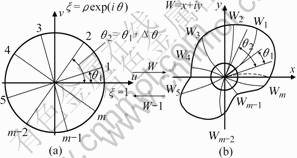
Fig.1 Mapping between complicated region and unit dish:(a) Unit dish; (b) Complex region
In polynomial Eqn.(1), cn=an+ibn is complex coefficient.
According to the orthogonality of trigonometric function, the coefficient cj of Eqn.(1) can be calculated as
 (2)
(2)
The coordinates value of mapping function points of given complicated region boundary is unknown corresponding to N part points of unit dish, so cj can not be calculated by Eqn.(2) directly. Here, the mutual iterative method between odd and even interpolation points were used to define interpolation points coordinates![]() and coefficients cj under given precise.
and coefficients cj under given precise.
The odd points sequences can be expressed by even points sequences as
 (3)
(3)
Then it can be simplified as below
![]() (4)
(4)
By same procedures, we can get even interpolation points sequences expressed by odd sequences.
![]() (5)
(5)
where ![]() ��
��![]() ��
��![]() and
and![]() are the transforming coefficients between the odd and even coordinates.
are the transforming coefficients between the odd and even coordinates.
In Eqn.(2), interpolation points can be defined as odd interpolation points when not satisfying precision requirements. Then, new interpolation points are added between odd interpolation points, namely even points. Further, both odd and even points do mutually iterative calculation until the interpolation points value and cj can be calculated under the condition of satisfying precision requirements.
3 Drawing forming modelingAs shown in Fig.2, the geometrical profile on the cross-section of hexagon tube billet ��z=L��can be described by Eqn.(1), L is the length of deforming region, r is the arc radii, then mapping function can be gotten.
 (��0�ܦѡ�1) (6)
It can map the cross-section region into unit dish region.
Fig.3 shows the deforming body sketch of drawing. In the deforming body, taking the center of billet as origin to set up Cartesian coordinate system (x, y, z). By Eqn.(6), the three-dimension analysis function of deforming region can be written as
(0��z��L, 0�ܦȡ�2��, ��0�ܦѡ�1)
 (7)
(7)
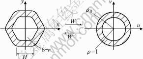
Fig.2 Conformal mapping between hexagon-shaped tube section and unit dish ring region
As shown in Fig.3, Si is the cross-section area of tube billet, over plastic forming, cross-section area S0 is obtained. When ![]() =1, Eqn.(7) becomes the parameter function of die cavity surface
=1, Eqn.(7) becomes the parameter function of die cavity surface ![]() .
.
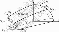
Fig.3 Drawing forming sketch
In Eqn.(6), f(z) is the vertical interpolation function of die cavity which should satisfy die cavity geometry boundary conditions. At the inlet and the exit of die cavity, Eqn.(7) should satisfy the outer profiles regions of Si and S0, as well as the plastic flow conditions. Boundary conditions are depicted as
![]() ,
, ![]() (8)
(8)
![]() ,
, ![]() (9)
(9)
When the vertical curve of die cavity belongs to cubic-polynomial, the function can be gotten.
![]()
From Eqns.(8) and (9), f(z) can be obtained as
![]() (10)
(10)
By the numerical calculating method of Conformal Mapping of the interpolation between odd points and even points, cj can be calculated, then uniting f(z) with
Eqn.(6), the parameter function of three-dimension die cavity surface can be set up, and the die cavity modeling of exact drawing (when��=1) can be carried out.
4 Metal plastic flow fieldIt is assumed that the drawing forming belongs to three-dimension stable plastic flow field, meanwhile, as shown in Fig.3, even distribution of flow velocity vz along z-axis direction is supposed to be vertical to z�Caxis on the arbitrary cross-section within deforming region. Hence, vz can be obtained from the character of flow tube as
 (11)
(11)
where Sz is the cross-section area of arbitrary position in deforming region; v0 is the axial drawing velocity, r0 is the inner radii of the tube.
By plastic deformation stream function theory, taking total differential equation to ![]() and
and ![]() of Eqn.(6) separately, the velocity field can be gotten.
of Eqn.(6) separately, the velocity field can be gotten.
 (12)
(12)
Here ![]()
![]() ��n=2, 3, ��,
��n=2, 3, ��, ![]() ��
��
From Eqns.(11) and (12), the strain velocity field can be calculated as[13]
 (13)
(13)
Suppose ![]() is the equivalent strain ratio;
is the equivalent strain ratio; ![]() is the metal plastic yield stress; V is metal��s volume in deforming region;
is the metal plastic yield stress; V is metal��s volume in deforming region; ![]() is shearing yield stress; m is friction factor;
is shearing yield stress; m is friction factor; ![]() are discontinuous velocity at the inlet and exit of die cavity, and
are discontinuous velocity at the inlet and exit of die cavity, and ![]() is the relative velocity between die cavity and metal surface. By upper bound method[14], metal��s total power dissipation is the sum of metal forming power dissipation
is the relative velocity between die cavity and metal surface. By upper bound method[14], metal��s total power dissipation is the sum of metal forming power dissipation ![]() , shearing power dissipation
, shearing power dissipation ![]() on the surfaces
on the surfaces ![]() and
and ![]() , as well as the friction power dissipation
, as well as the friction power dissipation ![]() on the surface
on the surface ![]() :
:
![]() =
=![]()
![]() +
+ ![]()
![]() (14)
(14)
Thus, the drawing relative load ratio can be calculated by
![]() (15)
(15)
Now bringing velocity field of drawing Eqn.(12) and strain velocity field Eqn.(13) into Eqn.(14), asking drawing relative load ratio Pt for extremum to L over Eqn.(15), then the optimized parameter L can be obtained, and die CAD modeling is achieved as well.
6 ExampleIn Fig.2(a), the cross-section side length of hexagon tube is H=10, geometrical center is (0,0), and the arc radius are r/H=0.3, then, the geometrical boundary condition in the first quadrant can be given.
 (16)
(16)
By numerical trigonometric interpolation method of Conformal Mapping, (the accuracy of cn can be computed by the normal convergence method[15]. In this case, 32 interpolating points represent the infinite points of Eqn(1) in the first quadrant), cn can be calculated as
![]() = 0.897 094, 0.000 073, 0.000 343 4, 0.039 462,
= 0.897 094, 0.000 073, 0.000 343 4, 0.039 462,
0.000 421, 0.000 03, 0.011 113, 0.000 064, 0.000 383,
0.004 214, -0.000 620, 0.000 18, 0.002 425, -0.000 049, -0.002 354, 0.000 27
![]() =0��
=0�� ![]() =1,...,16
=1,...,16
Suppose the tube billet��s outer diameter is d 2.4H��H=10 mm��, wall thickness is 1.2 mm, the product side length is H, arc radii is r=0.3H. When the cross section ratio is ��=0.825 and friction factor is m=0.7, by Eqn.(15), as shown in Fig.4, the optimized result is L=1.32H. Further, by Eqn.(7), die cavity CAD can be achieved as shown in Fig.5.
Fig.6 shows the cross section of hexagon tube drawing at different locations z of deforming region. Since there are six symmetrical axes at each section, the changing cycle of tangent flow is ![]() . The analysis of Eqn.(12) shows the largest tangent positive strain exists at the midpoint of each side during drawing, namely, the wall reaches the thinnest thickness. However, at the peak
. The analysis of Eqn.(12) shows the largest tangent positive strain exists at the midpoint of each side during drawing, namely, the wall reaches the thinnest thickness. However, at the peak
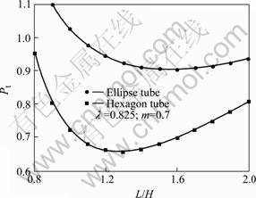
Fig.4 Die parameter optimization of special-shaped tube drawing
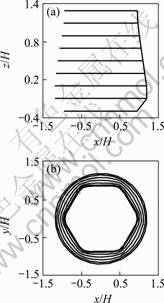
Fig.5 Optimized die cavity
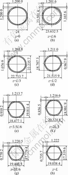
Fig.6 Cross section of hexagon tube drawing at deforming region
of the arc, as the tangent pressing strain is slightly larger than the positive strain of drawing force to this point, so the wall thickness changes weakly, and shows only a small increase.
Further, the tube billet will be shaped into ellipse-shaped tube product when its outer diameter is d 3H and wall thickness is 6mm, then the product��s half major axis is a=1.4H and half brachyaxis is b=1.2H. When the cross section ratio is ��=0.825 and friction factor is m=0.7, by Eqn.(15), as shown in Fig.4, the optimized result is L=1.55H.
Fig.7 shows the cross section of ellipse-shaped drawing at different locations z of deforming region. By the same procedures analysis, it is concluded the largest tangent drawing strain exists at the brachyaxis, where,
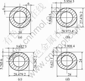
Fig.7 Cross section of ellipse tube drawing at deforming region: (a) z=0; (b) z=L/2; (c) z=2L/3; (d) z=L
the wall reaches the thinnest thickness. but at the major axis, as the tangent pressing strain is slightly smaller than the positive strain of drawing force to this point, so the wall thickness changes weakly, shows only a small decrease.
To sum up, during tube drawing, the metal��s wall thickness tends to decline when approaching to z-axis, but it shows smaller and smaller changes when being away from z-axis, even the thickness has a little incremental tendency.
7 ConclusionsBy the Conformal Mapping theory and numerical trigonometric interpolation methods between odd points and even points, both the drawing forming and mathematical model of die cavity surface are generated in special-shaped tube products process. Combining with modern processing technology, NC program and CAM of die cavity can be realized.
By the upper bound method, die cavity of special-shaped tube drawing is optimized, as well as, the changing principle of wall thickness during tube forming are concluded.
References[1] KEUN K. An upper bound solution of tube drawing[J]. J Mat Pro Tech, 1997, 63: 43-48.
[2] LAILA S. Round-to-square section drawing flat idle rolls[J]. International Journal of Mechanical Sciences, 1999, 41: 1323-1338.
[3] BOER C. Direct upper bound solution and finite element approach to round to square drawing[J]. Transaction of the ASME Journal of Engineering for Industry, 1985, (2): 107-254.
[4] TEPPATI C. Conformal-mapping design tools for coaxial couplers with complex cross section[J]. IEEE Transactions on Microwave Theory and Techniques, 2002, 50(10): 2339-2345.
[5] AMATORE C. Simulation of the double hemicylinder generator-collector assembly through conformal mapping technique[J]. Journal of Electroanalytical Chemistry, 2003, 553(S): 49-61.
[6] RAJALINGHAM C. Axisymmetric vibration of circular plates and its analog in elliptical plates using characteristic orthogonal polynomials[J]. Journal of Sound and Vibration, 1993, 161: 109-118.
[7] ZOU Ji-bin. Magnetic Circuit and Magnetic Field[M]. Harbin: Harbin Institute of Technology Press, 1998. (in Chinese)
[8] WU Guo-chuan. Tandem Blade Cascade[M]. Beijing: National Defence Industry Press, 1996. (in Chinese)
[9] QI Hong-yuan, ZHU Heng-jun. Conformal mapping modeling of metal plastic deformation and die cavity in special-shaped extrusion[J]. Trans Nonferrous Met Soc China, 2002,12(5): 858-861.
[10] QI Hong-yuan. Conformal analysis of fundamental frequency of vibration of simple-supported elastic ellipse-plates with concentrated substance[J]. Journal of Central South University of Technology, 2005, 12 (2): 269-273.
[11] WEN Guo-chun. Conformal Mapping and Boundary Problem[M]. Beijing: Higher Education Press, 1985.
[12] NETKU Y. Conformal Field Theory[M]. Cambridge Massachusetts USA: Perseus Pub, 2000.
[13] ZHAO Zhi-ye. Theory Basis of Metal Stress Process[M]. Beijing: Metallurgical Industry Press, 1989.
[14] Chitkara N R. Application of an upper bound method to off-centric extrusion of square section, analysis and experiments[J]. Inter J Mech Sci, 2000, 42: 321-344.
[15] QI Hong-yuan, ZHU Heng-jun. Chinese Postdoctoral Science Foundation[A]. Proceeding of Chinese Postdoctoral Academic Conference[C]. Beijing: Science Press, 2001. 484-488.
Corresponding author: QI Hong-yuan; Tel: +86-10-84853968; E-mail: qhy@jdxy.njtu.edu.cn
