
Electrochemical performance of microarc oxidation films formed on AZ91D alloy in two group electrolytes
WANG Li-shi(������), CAI Qi-zhou(������) , WEI Bo-kang(κ����), LIU Quan-xin(��ȫ��)
(State Key Laboratory of Die and Mould Technology, Huazhong University of Science and Technology, Wuhan 430074, China)
Abstract:
The phase composition and electrochemical performances of microarc oxidation(MAO) films prepared on AZ91D alloy by using step-down current method in a phosphate electrolyte(P-film) and silicate electrolyte(Si-film) were studied. The results show that P-film is mainly composed of Mg, MgAl2O4 and MgO, and Si-film is composed of Mg2SiO4 and MgO. There clearly exists a fluoride-enriched zone with the thickness of about 1-2��m for P-film and 0.7-1��m for Si-film at the MAO coating/substrate interface. The electrochemical tests show that both P-film and Si-film can enhance the corrosion resistance of AZ91D magnesium alloy significantly. The corrosion failure process of the two films in 5%(mass fraction) NaCl solution is quite different.
Key words:
AZ91D alloy; electrolyte; microarc oxidation; electrochemical performance CLC number: TG146.2;
Document code: A
1 INTRODUCTION
Microarc oxidation(MAO) is a process of plasma-assisted electrochemical conversion of a metal surface to produce an ceramic-type coatings. A key feature of the process is a plasma discharge that occurs at the metal/electrolyte interface when the applied voltage exceeds a certain critical breakdown value and appears as a number of discrete short-lived microdischarges moving across the metal surface. When applied to magnesium and its alloys, the MAO process allows thick, hard and well adhered ceramic-like coatings to be obtained with high corrosion resistance, thermal stability and dielectric properties[1, 2]. Therefore, MAO is one of the most prospective methods of surface treatment for magnesium and its alloys[3, 4].
The structures of MAO coatings depend on numerous factors. The chemical composition of the electrolyte exerts a decisive influence on the distinctive features of ceramic coatings. In alkaline electrolytes, metal ions generated in anodic reaction and other metal ions contained in the electrolytes easily transform into colloidal micro-particles with negative charge and are incorporated in the coating. These processes change the microstructure of the coating, which may cause the coating to possess new properties. So the alkaline electrolytes are used more popularly than the acidic electrolyte. In research papers and registered patents, alkaline phosphate and silicate electrolyte with different additives are often used to produce MAO ceramic coatings on magnesium and its alloys[5-7]. Unfortunately, the MAO process, phase composition, corrosion resistance and corrosion failure process of the ceramic-like films formed on Mg based alloys in phosphate(P-film) and silicate electrolyte(Si-film) have not been studied systematically up to now, which hinders the applications of the two electrolytes in MAO process of magnesium alloys and the development of new environmentally friendly electrolyte recipes.
The two kinds of electrolyte constituents employed in this study were phosphate and silicate with their individual different additives. The homemade power supply can provide bipolar pulses. The MAO process, characteristics and the corrosion failure of P-film and Si-film formed on AZ91D alloy were studied.
2 EXPERIMENTAL
2.1 Experimental materials
The AZ91D alloy used in this study was prepared by metallic mould casting in protective gases protection. The chemical composition is as follows(mass fraction): Al 9.1%, Zn 0.85%, Mn0.27%, Mg balance. The samples for salt spray and total immersion tests were machined to the size of 50mm��30mm��10mm. The dimensions of the samples for electrochemical tests were d11.29mm��10mm.
Based on the former experiments, two types of the effective and representative electrolyte constituents were employed. The first was an aqueous phosphate electrolyte(the coating formed in this solution was denoted as P-film) and its main components were (NaPO3)6 and Na3AlF6. The pH value of this recipe solution was in the range of 11-12 before MAO. The other was an aqueous silicate electrolyte(the coating formed in this solution was denoted Si-film) and its main components were Na2SiO3 and KF. Its pH value was in the range of 13-14 before MAO.
2.2 MAO processes
After polished successively up to 800 grade, followed by degreasing in acetone and rinsing in distilled water, the samples were immersed in the formulated aqueous electrolyte. The experiment was conducted using a high frequency(700Hz) bipolar current mode. The controlling mode was called by ��step-down current method��, as shown in Fig.1. This method can make the MAO process more stable and more effective. Firstly, a big electric current i0(7-9A/dm2) was used to strike in order to increase the voltage to V0 (200V), then electric current reduced to i1(4-6A/dm2) and held for some time(t1- t0). When the voltage got to V1(360V for P-film or 420V for Si-film), the electric current reduced to i2(0.5-1A/dm2) and then kept for some time(t2-t1). The two MAO processes were operated for 40min respectively. The temperature of the electrolyte was kept below 35��. A stainless steel plate was used as the counter electrode. The coated samples were rinsed in distilled water, dried in hot air and then kept in drying chamber for tests.
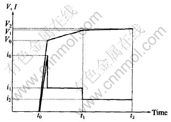
Fig.1 Schematic plan of parameters controlling during MAO process
2.3 Coating composition and phase analysis
For the cross-sectional analysis, the coated AZ91D samples were cut out and mounted with the glass reinforcement epoxy which ensured edge retention during the grinding and polishing. The morphology and chemical composition of the films were examined by using the microprobe of type JXA8800R. Because of its low conductivity, the original coating surface was sputter-coated with carbon prior to microstructure observation.
The phase composition of the films was estimated by XRD analysis using a D/Max ��B diffractometer(CoK�� radiation). The XRD analysis was conducted on the films together with the AZ91D substrate.
2.4 Electrochemical performance tests
Potentiodynamic polarization was carried out using AUTOTEST system and the scan rate was 2.5mV/s. The impedance measurements were conducted using a SI1250 frequency response analyzer connected to a Schlumberger SI1286 electrochemical interface. The AC frequencies ranged from 100kHz to 0.1Hz with a polarization amplitude of 10mV. A three-electrode cell with the sample as working electrode, saturated calomel electrode(SCE) as reference electrode and platinum sheet as counter electrode, was employed in this work. The open-circuit potential(OCP) measurements were used a saturated calomel electrode(SCE) and M273 potentiostat. The data were recorded manually.
Total immersion test was performed at room temperature. Salt spray test was performed in FAQ025 chamber under the conditions described in ASTM-B117. The test duration was conducted for 120h. The corrosion rate was evaluated by the method of mass loss.
To keep consistence of the data, all the solutions used in electrochemical and corrosion tests were 5%(mass fraction) NaCl prepared using analytical grade reagents in distilled water.
3 RESULTS AND DISCUSSION
3.1 Voltage��time curves
Fig.2 shows the voltage��time curves obtained during MAO processing of AZ91D alloy in two electrolytes. In the general case, several characteristic stages can be resolved in V��t curve during the MAO process[8, 9]. Region(1) exhibits maximum gradient on the voltage curve and corresponds to a conventional magnesium anodizing process. In region(2), the increasing rate of voltage slackens, which indicates that the oxide film growth rate decreases and oxygen bubbles first appear on the sample surface. In region(3), the increasing rate of voltage rises again and this usually corresponds to oxide recrystallization and defect appearance in the film structure. Region(4) begins with intensive oxygen evolution, which creates a background for the onset of plasma micro-discharge phenomena on the sample surface. In silicate electrolytes, region(2) is combined with region(3), which shows that this processes can reach the steady-state more easily than that in phosphate electrolytes. Moreover, the different final voltages reveal that the plasma chemical reactions at the substrate/electrolyte interface(phosphate and silicate electrolytes) are greatly different.
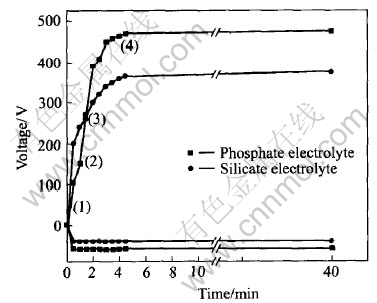
Fig.2 Typical variation of voltage amplitude of anode and cathode pulses
3.2 Coating morphology
A top view of the films formed on AZ91D alloy is shown in Fig.3. There apparently exist a lot of micropores with different diameters in P-film. However, noticeable micropores cannot be seen in Si-film. The difference of the surface morphology may result from the different final voltage. The final voltage can represent the plasma reaction state on the surface of the substrate[10]. Moreover, the different passivation mechanism of the phosphate and silicate for the AZ91D alloy may be another reason for the surface morphology difference between the two type films[11].
Fig.4 shows the cross-sections of the coatings. It can be seen that the P-film with the thickness of 37��m is more even compared to the Si-film with the thickness of 62��m in the uniformity of the film.
3.3 Phase composition
The XRD patterns for AZ91D alloy and the two type films are shown in Fig.5. The as-cast AZ91D magnesium alloy consists of a solid solution(��) phase and an intermetallic compound phase(Mg17Al12). It can be seen that P-film has the lowest peaks compared to those of Si-film. The mass fraction of individual phases formed in the MAO
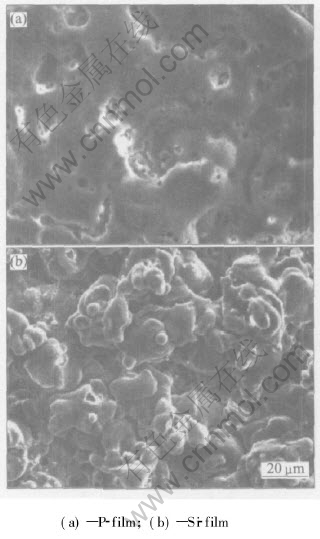
Fig.3 SEM images of surface of AZ91D alloy
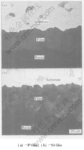
Fig.4 Cross-section micrographs of coatings
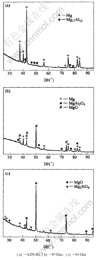
Fig.5 XRD patterns of AZ91D alloy and MAO films
films can be evaluated by the method of simplified K value[12, 13]. According to the formula[14]:

where Kjc is reference intensity; xj is mass fraction of j phase; Ij is the maximum intensity of j phase. The mass fraction of the phase composition is 33.5%Mg, 35.6%MgO, 30.9%MgAl2O4 for the P-film and 41%MgO and 59%Mg2SiO4 for the Si-film, which identifies that the type and the quantity of the electrolyte component have great influences on the composition of the films formed on AZ91D alloy.
In general, MAO coatings consist of the outer porous layer and the inner barrier layer[15, 16]. The composition and the quality of the barrier layer have great influence on the anti-corrosion performance of the oxide films. The composition of the barrier film is different from that of the outer layer, especially for fluorine content. Fig.6 shows the EDX results obtained around the coating/substrate interface of the Si-film. It is clearly shown that the barrier layer is composed of Mg, O, F and a small amount of electrolyte element. This suggests that fluoride may play a role during the course of the initial film formation. The EDX line scanning results show that there clearly exists a fluoride-enriched zone of about 1-2��m for P-film and 0.7-1��m for Si-film at the coating/substrate interface. Due to the low solubility product of MgF2, it can have a beneficial effect as inhibitor in the sense. In this experiment, the presence of fluoride in the oxide film is the result of the reaction between fluoride anion in the solution and Mg cation in the film. The increasing in local temperature due to sparking will also accelerate the growth of MgF2.
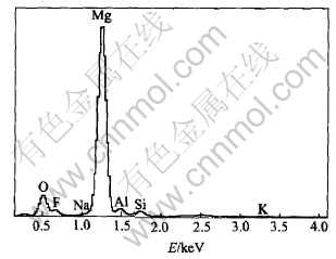
Fig.6 EDX analysis of chemical elements around Si-film/substrate interface
3.4 Electrochemical properties
The potentiodynamic polarization plots of the AZ91D, P-film and Si-film are given in Fig.7. The corrosion current density of AZ91D substrate, P-film and Si-film calculated from Fig.7 are 0.0413, 0.0035 and 0.0099mA/cm2, respectively. The results show that the corrosion rates of P-film and Si-film are about two orders of magnitude lower than that of the AZ91D substrate.
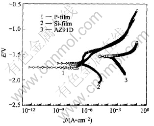
Fig.7 Potentiodynamic polarization curves
Fig.8(a) is bode plots of AZ91D, P-film and Si-film after immersion in 5%(mass fraction) NaCl solution for 2h. Curve fitting results show that MAO films have very high polarization electrical resistance(1.04��106�� for P-film and 2.62��105�� for Si-film), which proves that MAO films greatly enhance the corrosion resistance of AZ91D alloy.
Fig.9 shows the development of OCP with immersion time in 5%(mass fraction) NaCl solution for AZ91D and the two MAO films. For Si-film, its OCP increases in the initial period(less than 3.5h) and then decreases with immersion time in the later period. However, the development of OCP with immersion time for P-film is a little complex. In the first period(less than 6.5h), OCP decreases. In the second phase(6.5-30.5h), OCP increases. In the third period(>30.5h), OCP decreases again. The difference of the OCP-time curve between P-film and Si-film are related to the coating structure and surface porosity. In P-film, a lot of micropores with different diameters exist, the rapid initial penetration of the solution into the porous outer film results in decreasing of OCP. Then the hydration of MgO in the pores leads to the increase of OCP. With the thinning of the barrier layer and final corrosion failure, OCP decreases gradually. As to the Si-film, its OCP fluctuations only experience the later two periods. Fig.8(b) shows the bode plots of Si-film in 5%(mass fraction) NaCl solution at different immersion times. It clearly shows that the corrosion failure of Si-film is a gradual process.
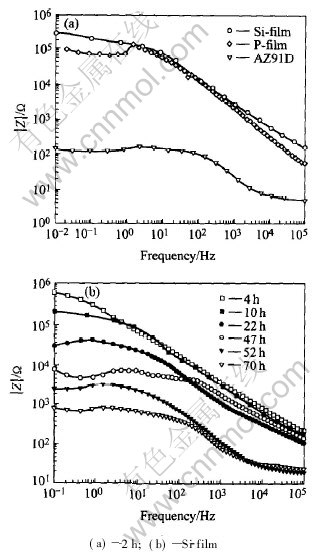
Fig.8 Bode plots after immersion in 5%(mass fraction) NaCl solution
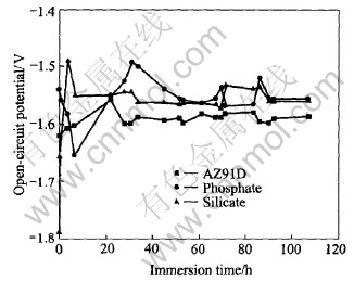
Fig.9 Variation of OCP with immersion time in 5%(mass fraction) NaCl solution
Fig.10 shows the macroscopic appearance of the samples after the total immersion test in 5%(mass fraction) NaCl for 120h. Few corrosion spots appear on the surface of the oxide films. The data in Fig.11 show that MAO films provide effective protection to the substrate of AZ91D alloy
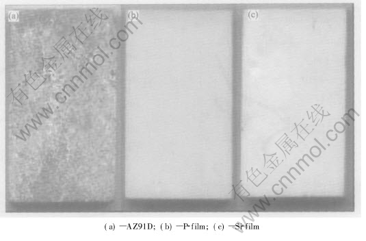
Fig.10 Appearance of samples after total immersion test in 5%(mass fraction) NaCl for 120h
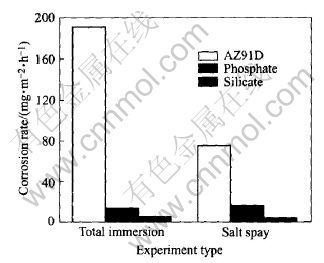
Fig.11 Average corrosion rate for AZ91D subjected to total immersion test and salt spray in 5%(mass fraction) NaCl for 120h
and enhance its anti-corrosion performance significantly. Furthermore, it is clear that the film produced in the silicate electrolyte has better corrosion resistance than that in the phosphate electrolyte.
4 CONCLUSIONS
1) Under the condition of the step-down current method, the characteristic stages of the V��t curve for the phosphate-based electrolyte are more evident than that for the silicate-based electrolyte. The different surface morphology of AZ91D alloy treated in the phosphate and silicate results from the different final voltage and passivation mechanism.
2) The electrolyte constituents exert a decisive influence on phase composition of the MAO films. The oxide films compose of Mg, MgO and MgAl2O4 for P-film and of MgO, Mg2SiO4 for Si-film. The element Si and P are uniformly distributed throughout the coating thickness and there clearly exists a fluoride-enriched area of about 1-2��m for P-film and 0.7-1��m for Si-film at the coating/substrate interface.
3) The corrosion failure processes of the P-film and Si-film in 5%(mass fraction) NaCl solution are quite different. OCP fluctuations experience two periods for Si-film and three periods for P-film. The OCP-time curve difference between P-film and Si-film are related to the coating structure and surface porosity.
4) Both P-film and Si-film can enhance the corrosion resistance of AZ91D alloy significantly, and the later is more effective.
REFERENCES
[1]Yerokhin A L, Nie X, Leyand A, et al. Plasma electrolysis for surface engineering [J]. Surface and Coating Technology, 1999, 122: 73-93.
[2]Yerokhin A L, Snizhko L O, Gurevina N L. Discharge characterization in plasma electrolytic oxidation of aluminum [J]. Journal of Physics D: Applied Physics, 2003, 36: 2110-2120.
[3]CAI Qi-zhou, Wang Li-shi, Wei Bo-kang. Present research status and developing tendency on corrosion resistant technologies for Mg alloy [J]. Nonferrous Alloy and Special Casting, 2003, 3: 33-35.(in Chinese)
[4]XUE Wen-bin, DENG Zhi-wei, LAI Yong-chun, et al. Review of microarc oxidation technique on surface of nonferrous metals [J]. Heat Treatment of Metals, 2000, 1: 1-3.(in Chinese)
[5]YU Gang, LIU Yue-long, LI Ying, et al. Corrosion and protection of magnesium alloys [J]. The Chinese Journal of Nonferrous Metals, 2002, 12(6): 1088-1098.(in Chinese)
[6]Zozulin A J. Anodized coatings for magnesium alloys [J]. Metal Finishing, 1994, 3: 39-44.
[7]Bartak D E, Lemieux B E, Woolsey E R, et al. Two-Step Electrochemical Process for Coating Magnesium Alloys [P]. US 5264113, 1993.
[8]Oscar K, Danny W, Joseph Y. Anodizing of pure magnesium in KOH-aluminate solutions under sparking [J]. Journal of the Electrochemical Society, 1999, 146(5): 1757-1761.
[9]Snizhko L O, Yerokhin A L, Pilkington A, et al. Anodic processes in plasma electrolytic oxidation of aluminum in alkaline solutions [J]. Electrochimica Acta, 2004, 49(13): 2085-2095.
[10]Xia S J, Yue R G, Rateick R G, et al. Electrochemical studies of AC/DC anodized Mg alloy in NaCl solution [J]. Journal of the Electrochemical Society, 2004, 151(3): B179-B187.
[11]ZHANG Tian-sheng. Inhibitor [M]. Beijing: Chemical Industry Press, 2002.(in Chinese)
[12]XUE Wen-bin, DENG Zhi-wei, LAI Yong-chun, et al. Analysis of phase distribution for ceramic coatings formed by microarc oxidation on aluminum alloy [J]. Journal of American Ceramic Society, 1998, 81(5): 1365-1368.
[13]YANG Guang-liang, L�a Xian-yi, BAI Yi-zhen, et al. The effects of current density on the phase composition and microstructure properties of micro-arc oxidation coating [J]. Journal of Alloys and Compounds, 2002, 345(1-2): 196-200.
[14]LIU Yue-hui, LIU Pin-gan. Principle and Application of X-ray Diffraction Analysis [M]. Beijing: Chemical Industry Press, 2003.(in Chinese)
[15]Oscar K, Danny W, Joseph Y. Structure and composition of anodic film formed on binary Mg-Al alloys in KOH-aluminate solutions under continuous sparking [J]. Corrosion Science, 2001, 43: 1295-1307.
[16]Birss V, Xia S, Yue R, et al. Characterization of oxide films formed on Mg-based WE43 alloy using AC/DC anodization in silicate solutions [J]. Journal of the Electrochemical Society, 2004, 151(1): B1-B10.
Foundation item: Project(2002ABB051) supported by the Natural Science Foundation of Hubei Province and the Research Foundation of HUST, China
Received date: 2004-09-07; Accepted date: 2004-12-22
Correspondence: WANG Li-shi, PhD candidate; Tel: +86-27-87543876; E-mail: wlshust@sohu.com
