

J. Cent. South Univ. (2019) 26: 1755-1768
DOI: https://doi.org/10.1007/s11771-019-4131-6

Kinematic analysis of geosynthetics-reinforced steep slopes with curved sloping surfaces and under earthquake regions
ZHOU Jian-feng(�ܽ���)1, QIN Chang-bing(������)2, PAN Qiu-jing(���ᄚ)3, WANG Cheng-yang(������)3
1. College of Civil Engineering, Huaqiao University, Xiamen 361021, China;
2. Department of Civil & Environmental Engineering, National University of Singapore,Singapore 117576, Singapore;
3. School of Civil Engineering, Central South University, Changsha 410075, China
 Central South University Press and Springer-Verlag GmbH Germany, part of Springer Nature 2019
Abstract:
A procedure of kinematic analysis is presented in this study to assess the reinforcement force of geosynthetics required under seismic loadings, particularly for steep slopes which are hardly able to maintain its stability. Note that curved sloping surfaces widely exist in natural slopes, but existing literatures were mainly focusing on a planar surface in theoretical derivation, due to complicated calculations. Moreover, the non-uniform soil properties cannot be accounted for in conventional upper bound analysis. Pseudo-dynamic approach is used to represent horizontal and vertical accelerations which vary with time and space. In an effort to resolve the above problems, the discretization technique is developed to generate a discretized failure mechanism, decomposing the whole failure block into various components. An elementary analysis permits calculations of rates of work done by external and internal forces. Finally, the upper bound solution of the required reinforcement force is formulated based on the work rate-based balance equation. A parametric study is carried out to give insights on the implication of influential factors on the performance of geosynthetic-reinforced steep slopes.
Key words:
Cite this article as:
ZHOU Jian-feng, QIN Chang-bing, PAN Qiu-jing, WANG Cheng-yang. Kinematic analysis of geosynthetics-reinforced steep slopes with curved sloping surfaces and under earthquake regions [J]. Journal of Central South University, 2019, 26(7): 1755-1768.
DOI:https://dx.doi.org/https://doi.org/10.1007/s11771-019-4131-61 Introduction
In engineering practice, some pre-emptive countermeasures such as installation of geotextiles or piles are taken to offer additional resistance, particularly for steep slopes subject to heavy earthquake effect. It is of interest for engineers to assess the resistance force necessitated to maintain slope stability. A commonly used approach, kinematic analysis, will be employed in this study to resolve such a problem. The kinematic approach within the framework of plasticity theory indicates that the load calculated from the equilibrium of the external and internal rates of work is not less than the actual failure load within the boundary conditions [1]. Owing to its conciseness and simplicity with no-stress calculations involved in a specific analysis, many researchers [2-8], applied this approach to evaluating the slope stability using a log-spiral velocity discontinuous surface. Such a failure surface is a sound approximation to the physical failure in a homogeneous soil slope, and it is limited to account for a constant soil friction angle with a prescribed failure pattern, as substantiated in Ref. [9]. Therefore, such a conventional approach is hardly able to consider non-uniformity of soil properties, such as soil friction angle and unit weight, with a log-spiral failure mechanism a priori. In an effort to overcome this shortcoming, the discretization technique was proposed. Such a technique enables one to break down the whole problem into discretized components, and readily account for the non-uniform soil properties in the process of generation of a kinematically admissible collapse mechanism. MOLLON et al [10] initially predicted the face stability of a pressurized tunnel, for both the collapse and blow-out case, with a two-dimensional and three-dimensional failure mechanism generated by this technique. Based on this line of thought, QIN et al [11, 12] also applied this principle to generating a failure surface for assessment of seismic slope stability.
Slopes in earthquake-prone regions are more vulnerable to landslides, which may pose enormous impacts to people��s lives and property. A proper inclusion of seismic effect is vital in predicting seismic slope stability. The most reliable approach is to use the actual acceleration time-history as the input; however, it is principally applied for numerical analyses with much computational effort necessitated. In response to maximally simplify the seismic input, the pseudo-static approach using constant horizontal/vertical acceleration is widely used in theoretical derivation. Notice that the constant acceleration is usually selected from the peak value of acceleration time-history, thereby yielding conservative solutions to slope stability problems. It is seen that the former consumes much computational time and is hardly able to be incorporated into theoretical analyses, while the latter cannot characterize the dynamic effect of an earthquake. In an effort to retain the simplicity of the pseudo-static approach and dynamic characteristics of an earthquake, a compromise is attained with the use of pseudo-dynamic approach. Initially, the pseudo-dynamic analysis was applied to investigating the external/internal stability of a retaining wall with or without geosynthetics [13, 14]. Therein, the horizontal and vertical accelerations were expressed in sinusoidal waves without considering initial phase lag [13, 15]. Note that the above analyses were mainly presented with the limit equilibrium method. Recently, such an approach was extended to kinematic analysis of seismic slope stability, and shown to be capable of yielding more reliable solutions [12].
As stated earlier, reinforcing structures are constructed to offer greater stability with additional resistance provided by stabilizing piles or geosynthetics. Some researchers [16, 17] investigated the stability of pile-reinforced slopes with the upper bound analysis, which is proven to be valid to improve slope stability. In the case of failure patterns of geosynthetic-reinforced slopes, they are dependent on the length, layout density and distribution of geosynthetics. The pseudo-static solutions of reinforcement force and length of geosynthetics required were derived with limit equilibrium, considering different failure patterns and horizontal acceleration only [18]. Apart from limit equilibrium analysis, the kinematic analysis of reinforced soil structures was performed by MICHALOWSKI [19, 20], with rigorous bounds obtained on the reinforcement strength and limit loads. In the design of a reinforced slope, the slope with geosynthetics was analyzed in a pseudo-static manner, considering rotational and sliding failure mechanisms, and a procedure was developed based on earthquake-induced permanent displacement [21]. Further, the pseudo-dynamic approach was used to replace the commonly-used pseudo-static in assessment of the internal stability or for tieback analysis of a reinforced soil wall [14]. Another extension of kinematic analysis of seismic slope stability is the use of non-associated flow rule combined with the pseudo-dynamic analysis [22]. VAHEDIFARD et al [23] employed the limit equilibrium method to investigate the stability of a geosynthetic-reinforced concave slope, aiming at determining the optimal profile of facing elements in geosynthetic-reinforced soil structures. In order to evaluate the combined effects of uncertainties on the structure��s performance, the reliability-based approach was applied to the slope stability analysis based on EC7 partial factor design method, with geosynthetics installed for steep slopes [24]. JAVANKHOSHDEL et al [25] investigated internal and external failure mechanisms of slopes reinforced by horizontally installed geosynthetics, having obtained the correlations between factor of safety, reinforcement strength and length through Monte Carlo simulation. Employing the discretization-based kinematic analysis, the geosynthetic-reinforced force required were discussed for steep slopes which are vulnerable to fail under earthquake disturbance [26, 27].
2 Methodology
2.1 Upper bound theorem
As a concise and effective approach, the upper bound theorem is commonly used in engineering practice in the analysis of slope stability, ultimate bearing capacity of foundation and earth pressure calculations. It is established from the perspective of energy (rate), and the critical state is reached in the condition of equilibrium of external and internal rates of work. Based on the upper bound analysis, the actual collapse load is no larger than the limit load calculated from the work rate-based balance equation within boundary conditions [1]. In a mathematical manner, the expression depicting the upper bound theorem gives
 (1)
(1)
where ��ij and ��ij are the stress tensor and strain rate at failure in a kinematically admissible velocity field, respectively; Ti refers to the surface load on the boundary s; Xi is the body force within the volume of a failure block ��; and Vi denotes the velocity along the failure surface. For ease of practical use, the upper bound analysis is applied for a rigid failure block, with soil materials being perfectly plastic and following the associated flow rule. Such a rule is the fundamental principle for proposing the discretization technique as elaborated in the next section.
Equation (1) is the basis in the application of upper bound theorem, based on which more scenarios can be accounted for, such as pore water effect and reinforced structures. Apart from internal forces generated within soils, other influential factors can be regarded as external forces, playing different roles in generation of a potential failure block. For instance, the pore water effect has an adverse consequence on slope stability; however, installation of reinforced structures like geotextiles is capable of strengthening slope capacity. This is attributed to additional resistance provided by geotextiles for the latter. The resistance effect can be considered as external force or internal force, both yielding the same results. For the case of a geosynthetics type, geogrids or geotextile, only the tensile strength aids to offer resistance, ignoring the negligible resistance to torsion, bending and shear. Accordingly, the tensile failure of reinforcement is investigated herein. This is achieved by assuming a sufficient length of geosynthetics, avoiding pull-out and shear failure. In order to ensure kinematic admissibility in a specific analysis, the velocity jump vector, [v], makes an angle of internal friction �� to the failure surface. Referring to MICHALOWSKI [20], the dissipation rate per unit area of the velocity discontinuity presents
 (2)
(2)
where t is the thickness of the shear band; �� denotes the inclination angle for geosynthetics intersecting a velocity discontinuous surface; kt is the average strength of the reinforcement; denotes the strain rate in the reinforcement which is taken as positive in tension and expressed as
 when
when  disregarding the reinforcement in resisting compression), where [v] is the velocity jump vector, and �� is soil friction angle.
A complete form of upper bound theorem considering the effect of geosynthetics is then developed by incorporating Eq. (2) into Eq. (1). This general form used in the following calculations presents

 (3)
(3)
2.2 Discretization technique
The discretization technique is developed to generate a kinematically admissible failure mechanism. It aids to account for non-uniform soil properties including soil unit weight, cohesion and friction angle, and facilitates the application of kinematic analysis considering complex scenarios. As mentioned earlier, a constant-angle log-spiral failure surface within c-�� materials in shape is prescribed in conventional upper bound slope stability analysis, which is attributed to the use of associated flow rule requiring that the plastic normal strain is inclined at an angle of ��/2+�� to the plastic shear strain. This rule is also used in the discretization technique when determining the discretized points along the contour of failure surface.
As elaborated in Ref. [12], the principle of discretization technique lies in the ��forward difference�� method, i.e., systematically generating the potential failure surface using the previous known point on the contour of the mechanism. For ease of formulation in the later kinematic analysis, a brief description of this technique is presented herein. It is well known that gentle slopes are more likely to maintain its stability, and failure usually occurs in steep slopes. In an effort to enhance the stability of steep slopes, geosynthetics are installed for preventing the possibility of landslides. A toe failure mode is suited to a steep slope with c-�� materials following perfect plastic flow.
In the process of point generation, the potential failure surface commences at slope toe and ends at the ground surface, as shown in Figure 1(a). Based on the coordinate system with the origin placed at slope toe, the key is to determine the discretized points along a potential slip surface point by point. This is achieved with an angular discretization procedure with a triangle enclosed by two radial lines and a section of slip surfaces, demarcated by O, Pi and Pi+1. Each triangle is regarded as a rigid failure block, rotating around the same centre O. The angle between two radial lines, ��, is user-defined and usually kept as a constant. Intuitively, a smaller �� value produces denser points along the failure surface. The choice of �� value affects the accuracy of kinematic solutions and computational effort required. Its effect was discussed in Ref. [12] where selection of ��=0.1�� could meet the accuracy requirement and save computational time. For a rotational toe failure pattern, two independent variables, such as the initial radius, r0, and initial angle, ��0, would suffice to depict the whole velocity discontinuity, as illustrated in Figure 1(a). Thereof, the rotation centre is denoted as O (xo, yo) and can be directly expressed with r0 and ��0.
A specific procedure for determining the next point Pi+1 (xi+1, yi+1) along the contour of failure surface is briefly presented herein based on the coordinates of point Pi (xi, yi). The rotational failure mode permits the velocity vector at point Pi,  gives
gives  where ��i is the angle between the radial line OPi and horizontal line as presented in Figure 1(a). Within the scope of Mohr-Coulomb (MC) criterion, the associative flow rule requires the velocity vector vi to meet the unit normal vector
 at an angle of soil friction. To encompass wider scenarios, the non-uniformity of soil friction angle with depth is denoted by profile ��(yi). Accordingly, it presents
 (4)
(4)
Another explicit relationship lies in the normality condition between vector ni and PiPi+1, i.e.,
 (5)
(5)
After arithmetic and vector reasoning, the coordinates of point Pi+1 are determined as
 (6)
(6)
where ��i+1 is the radial length of the vector OPi+1 and expressed as
 (7)
(7)
A more detailed description of the above procedure can be found in Ref. [12]. The constraint for point generation is  and the final xi+1 should be refined for the case of
  using linear interpolation herein. After having obtained the discretized points meeting the above conditions, a kinematically admissible failure surface is generated by connecting non-standard curves PiPi+1. Through discretization of the whole problem into elements, not only the non-uniform soil friction angle can be readily accounted for in generation of a failure mechanism, but also other complicated scenarios including non-uniform soil properties, curved sloping geometry and external loading are considered in a discretized kinematic analysis.

Figure 1 Internal failure mechanism of geosynthetic-reinforced steep slope with curved sloping surface (a) and non-uniform soil strength profiles (b)
2.3 Pseudo-dynamic approach
The pseudo-static approach has been of long interest for engineers to perform a rough prediction of slope stability; however, a conservative solution is more likely to be induced. On the other hand, the prediction accuracy of seismic slope performance could be greatly improved with actual acceleration time-history in time domain, at the expense of much computational effort consumed. A compromise is made with the pseudo-dynamic approach, retaining the dynamic characteristics of ground shaking and simplicity of the pseudo-static. Such a quasi-static analysis is capable of considering the time- dependent seismic effect, and hence likely to yield reliable solutions.
Pseudo-dynamic approach considers finite primary and shear wave velocities within slopes. The shear wave velocity is defined as  and the primary wave velocity
  where G is shear modulus, �� soil density and �� Poisson ratio. For common geomaterials with ��=0.3, Vp/Vs=1.87. Analogous to the pseudo-static approach, both horizontal and vertical accelerations are considered for completeness, although the vertical seismic effect is rather minimal when compared to the horizontal. A commonly used approach is to use sinusoidal functions to represent horizontal and vertical accelerations. This is logical since each seismic signal can be expressed as a weighted sum of sinusoidal signals by the means of Fourier transform. In the preliminary study, both horizontal and vertical accelerations are assumed to commence at the slope base at the same time without considering initial phase lag between these two inputs. Moreover, the amplification effect of acceleration propagating from slope toe to slope crest is considered with a soil amplification factor f. In the field, the initial phase shift between seismic inputs may exist due to geological and seismic conditions, and the factor f may not be a constant with depth. Nevertheless, it cannot be readily accounted for in the existing literatures. Resorting to the discretized kinematic analysis, the complicated cases including the above mentioned effects can be considered with ease from the perspective of elementary analysis.
Assuming that the horizontal and vertical accelerations reach khg and kvg in amplitude at slope toe surface, where kh and kv are horizontal and vertical seismic coefficients, the seismic signals at depth yi above the slope toe at time t are written as
 (8)
(8)
where Ts and Tp are periods of shear and primary seismic waves; ��s (=TsVs) and ��p (=TpVp) denote the wavelength for shear and primary waves; and t0 is the initial phase lag between horizontal and vertical accelerations at the slope base.
3 Kinematic analysis of reinforcement force
In this study, the critical slope failure is investigated considering the seismic effect. For the case of steep slopes subject to earthquake, its stability is hardly able to be maintained on its own, and hence reinforcement structures are required to provide additional resistance. A geosynthetics type with geogrids or geotextile is used, considering tensile failure only in this kinematic analysis. The specific analysis lies in work rate calculations for establishing an objective function, the required reinforcement force herein. Thereof, the external rates of work come from soil weight of the incipient failure block, surcharge loading and seismic forces, and the internal work rates stem from soil and geosynthetic resistance. Based on the discretized failure mechanism generated with the forward difference method, the external and internal rates of work are calculated from elementary analysis, which enables one to account for various scenarios.
There are some conditions where sloping surface is not always planar, presenting curved facing profiles which commonly exist in natural slopes. To date, related research is hardly able to be found due to its complexity in conventional kinematic analysis. However, such a problem can be readily resolved in this study using the proposed approach �C discretized kinematic analysis. In theory, a random facing profile can be accounted for in a specific kinematic analysis. For ease of calculation, the sloping surface with a monotonous function is considered. The following section gives a specific procedure for determination of reinforcement force required for slope stability.
Considering that the amplitudes of horizontal and vertical accelerations at the same level are unchanged at time t, a shape of horizontal trapezoidal element is chosen for work rate calculations. Given a discretized collapse mechanism, an element PiQiQi+1Pi+1 is taken as an example, as shown in Figure 2(a). Note that point Qi and Qi+1 are positioned at sloping surface, with the same ordinate values as Pi and Pi+1, respectively. The abscissa of points Qi and Qi+1 are calculated from the inverse function of the sloping profile. For instance, given a monotonous function of the sloping profile, f(x), its inverse function is expressed as f -1(x) in the condition that it exists. In this way, the abscissa can be directly computed from the ordinate value. Within the established coordinate system, the infinitesimal area of this element Ai gives
 (9)
(9)
In an effort to express the rate of work done by body forces, the gravity centre Ci (xoi, yoi) should be determined for each element. Its coordinates can be expressed as
 (10)
(10)
Based on a rotational failure mechanism, the direction of velocity vector is prescribed as normal to the vector OPi, and the value defined as the dot product of the angular velocity at failure �� and the radius from the rotation centre to the gravity centre for each infinitesimal element, i.e.,
 (11)
(11)
Assuming that the failure mechanism is generated with i+1 points, a total of i trapezoidal elements are counted. Accordingly, the overall rate of work done by soil weight is obtained through summation of the elementary rates of work, i.e.,

 (12)
(12)
where ��(yi) is to describe the variation of soil unit weight along ordinate yi; ��gi is the angle between the vector OCi and the ground surface as illustrated in Figure 2(b).
In a similar pattern, the rates of work produced by the horizontal and vertical seismic forces are expressed as
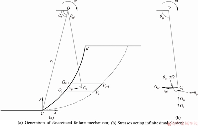
Figure 2 Elementary analysis of trapezoidal element PiQiQi+1Pi+1:
 (13)
(13)
For a possible surcharge loading located on the slope crest surface, such as a strip footing, it has a direct effect on slope stability if the surcharge is positioned within the failure area. Otherwise, its effect out of this scope can be ignored at ultimate limit state. A uniform surcharge loading leads to

 (14)
(14)
where q is the surcharge loading; xA refers to the abscissa of point A; �� is the slope angle, and coefficient m0 is defined as the ratio of the edge distance to the slope height H.
As a permanent force, the earthquake-induced seismic force for surcharge loading is accounted for. For ease of simplification, the thickness of potential surcharge is not considered, and in this case, the accelerations are the same as those propagating to slope crest surface, namely,
 (15)
(15)
As a consequence, the rates of work for seismic forces of surcharge yield
 (16)
(16)
For an incipient failure block, the soil strength resists the occurrence of landslides. When the failure block slides along the velocity detaching surface, shear forces are generated in the form of dissipated energy which is derived from the plastic deformation only under the rigid assumption. For MC soil materials, the internal rate of energy dissipation is defined as the dot product of the shear force and the velocity vector. Considering a discretized failure mechanism with i trapezoidal elements, the total internal rates are calculated by the sum of the elementary rates, i.e.,
 (17)
(17)
where c(yi) and ��(yi) are profiles of soil cohesion and friction angle at ordinate yi; Li denotes the length of vector PiPi+1 which is expressed as
 (18)
(18)
and the radius from point O to Pi gives
 (19)
(19)
It is well-known that steep slopes are incapable of maintaining stability by its intrinsic strength. Geosynthetics are installed for providing additional resistance in this study. As stated earlier, the tensile failure pattern is considered herein, and the internal failure mechanism is as shown in Figure 1(a). Such a failure is induced provided that the length of geosynthetics is large enough.
The geosynthetic resistance is incorporated into the upper bound theorem in the methodology part. In a specific kinematic analysis, it should be assured that the velocity vector makes an angle of internal friction to the shear band or rupture surface so as to meet the kinematical admissibility. For ease of simplification, the geosynthetics are assumed to be installed with uniform distributed tensile stress in i layers. Given a discretized collapse mechanism, the angle of inclination of the reinforcement layer to the failure surface ��i gives
 (20)
(20)
The rate of work produced by geosynthetics is expressed in Eq. (2) for a single layer of reinforcement. Therefore, the overall work rates are computed through summation of the elementary rates of i elements, i.e.,

 (21)
(21)
where f(ti) is the distributed tensile stress.
Based on the upper bound theorem, the equilibrium between the external and internal rates of work, 
 yields the kinematic solution of the reinforcement force required for slope stability, in the form of
  in two dimensions. Specifically, the total reinforcement force required is formulated as

 (22)
(22)
It is found from Eq. (22) that the reinforcement force Fr is a function of three independent variables,  using the pseudo-dynamic approach to represent time and space-dependent seismic accelerations. The optimal upper bound solution of the force Fr can be sought by optimizing the above non-linear function with enumerative algorithm under specific boundary conditions, and the results will be presented later in further detail under known parameters.
4 Comparison and discussion
The preceding analysis is mainly placed on pseudo-dynamic analysis of geosynthetic-reinforced steep slopes, yielding an upper bound solution of reinforcement force required for slope stability. Note that the pseudo-static approach is solely a simple case of the pseudo-dynamic, and hence the pseudo-static solution can be readily derived from the earlier analysis. Specifically, this is achieved by replacing the time- and space-dependent accelerations with constant ones, khg and kvg. In such a manner, the reinforcement force Fr is determined by two independent variables, namely, 
In order to validate the robustness of the proposed approach and the code for determining the kinematic solution, comparison with existing publications is performed. Since little theoretical research has been found for slope analysis with a curved sloping profile, a straight comparison is made considering a planar sloping surface herein. Initially, the pseudo-static solutions obtained in this study are compared with those with limit equilibrium method, including LING et al [18] where the internal and external stability of geosynthetic-reinforced soil structures were assessed with an analytical model implemented in the ReSlope programme, and SHAHGHOLI et al [28] with horizontal slice method (HSM). Figure 3 presents the pseudo-static solutions of the required geosynthetic reinforcement force  for the cases of kh=0, 0.1, 0.2 and ��=20��, 25��, 30�� with c=0, ��=90��, H=5 m, m0=0, q=0, ��=18 kN/m3 and ��v=0. It is found that apart from some different at lower earthquake, the kinematic solutions of this study are in good agreement with the limit equilibrium solutions, substantiating the validity and applicability of the proposed approach and programming code. Comparatively, the optimal upper bound solution is on the whole a bit larger than those calculated from the two mentioned literatures, which is attributed to the fact that the kinematic analysis yields an upper bound to a specific problem. Such a gap between limit analysis and equilibrium solutions gradually narrows down with the increase in horizontal seismic coefficient kh, implying that the proposed kinematic analysis aids to produce a superior upper bound under heavier earthquakes.
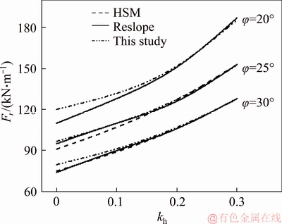
Figure 3 Comparison of pseudo-static solutions of geosynthetic reinforcement force
Apart from pseudo-static solutions, the pseudo- dynamic solutions of the required geosynthetic reinforcement force  are calculated and compared with those in NIMBALKAR et al [14]. In such a pseudo-dynamic analysis, a homogeneous soil slope is accounted for with the parameters corresponding to: c=0, ��=90��, H=5 m, Vs=100 m/s, Vp=187 m/s, f=1.0, Ts=Tp=0.3 s, m0=0, q=0, ��=18 kN/m3, ��v=0 and t0=0. The numerical results are shown in Figure 4 where the discrepancies are deemed acceptable in engineering practice. Similar as above, the upper bound solutions of required reinforcement force increase slowly than the limit equilibrium with the increase in kh. Therefore, a smaller upper bound solution is yielded under large seismic loadings, in comparison with the limit equilibrium solution.
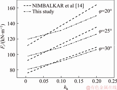
Figure 4 Comparison of pseudo-dynamic solutions of required reinforcement force
5 Numerical results
As presented in Eq. (22), the upper bound formulation of the required reinforcement force is established based on the work rate-based balance equation, with the optimal solution sought by optimizing the objective function under given parameters. Notice that a curved sloping surface is considered in the earlier analyses to encompass wider scenarios. In practice, there are three classical sloping profiles: concave, convex and planar. Since a planar surface was mostly adopted in slope stability analysis, and for ease of filling up the gap where concave and convex surface may exist, focus was placed on the effect of these two sloping surfaces in this paper. It is not uncommon to see a curved sloping surface in engineering practice. In many slope stability analyses, a planar surface is convenient and may be only feasible to be considered, so the approximation of a curved surface to be a planar one is usually adopted. In a sense, the accuracy of slope stability solutions is accordingly dependent on the approximation. In an effort to provide a more direct and accurate solution, the discretization-based kinematic analysis proposed in this study could well resolve this problem, because of its versatility to consider complicated sloping profiles and other loading conditions. It is worthwhile highlighting that the two functions used below are just two examples of concave and convex slopes, and this is to demonstrate the effect of sloping profiles on seismic slope stability.
 (23)
(23)
The specific pseudo-dynamic solution of the geosynthetic reinforcement is calculated based on the basic input parameters: H=5 m, ��=85��, m0=0, q=0, ��v=0..5, Vs=100 m/s, Vp=187 m/s, f=1.0, Ts=Tp=0.3 s, t0=0, ch=0, c0=20 kPa, ��h=10��, ��0=30��, ��h=14 kN/m3, ��0=22 kN/m3. A linear variation of soil properties including soil unit weight, cohesion and friction angle is assumed in the calculations for ease of simplification, which is logical in normally consolidated or deposited soils. A random profile of soil parameters can also be accounted for with the proposed approach. The optimal solution is presented in the form of figures with the reinforcement force normalized as  where �� is the average unit weight. A comparison between the kinematic solutions computed from three sloping surfaces is highlighted.
5.1 Effect of seismic acceleration
In this study, the focus is placed on the use of the pseudo-dynamic approach for depiction of seismic vibration rather than the pseudo-static. As is seen from Eq. (8), the horizontal and vertical acceleration are influenced by soil amplification factor, f, seismic velocity, Vs (Vp), shaking period, T (assuming Ts=Tp=T), initial phase lag, t0, seismic coefficients kh and kv (kv=��v kh). Its effect is presented in the following figures.
Figure 5 shows the implication of soil amplification factor f on the reinforcement force required for stability of steep slopes. A significant increase in normalized force is observed with an increment in horizontal seismic coefficient, kh. Similar trend goes for an increasing factor f, requiring further additional resistance from geosynthetics. This is sensible since a larger value of quantity f or kh implies more driving forces acting on the potential failure block, and hence more vulnerable to landslides for steep slopes. For the case of no earthquake, the solutions converge to a specific point regardless of f values. More interestingly, it is highlighted that concave slopes are more capable of maintaining its stability, with less reinforcement force required, followed by planar and convex slopes. For an incipient failure with the same failure surface, less weight of failure block and corresponding seismic forces are produced. This may also be attributed to the arching effect of the concave surface to resist slope failure. As illustration, the critical failure surface is readily plotted with the use of discretization technique, as shown in Figure 6. Intuitively, a stronger earthquake is likely to induce a much larger failure block. The difference in failure area between three facing profiles is insignificant, which in turn indicates a more stable slope surface with the concave profile.
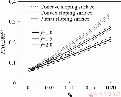
Figure 5 Effect of factor f and kh on normalized reinforcement force considering three facing profiles
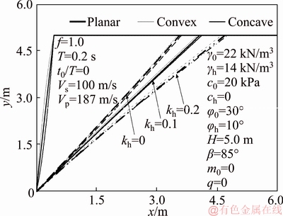
Figure 6 Critical failure surfaces under different seismic and geometry scenarios
In earlier publications, the horizontal acceleration was highly paid attention to due to its significance on slope stability, particularly in a pseudo-static analysis. The critical seismic case is under the case of seismic horizontal force acting outwards of the sloping surface. The vertical acceleration is usually ignored due to its presumed minimal effect in practice. For completeness, both horizontal and vertical accelerations are considered with the pseudo-dynamic approach in this study, and its effect is illustrated in Figure 7, where the normalized force is plotted against different kh and ��v (��v=kv/kh) ratios. Similarly, a larger resistance force is required from geosynthetics with the increase in ratio kh and ��v. The higher capacity to maintain slope stability is again substantiated in concave facing profile.

Figure 7 Effect of kv (��v) and kh on normalized reinforcement force considering three facing profiles
The influence of shear velocity Vs on the required reinforcement force is presented in Figure 8 where Vs varies from 100 to 200 m/s. In comparison with significant effect of horizontal seismic coefficient kh, a negligible increase of required reinforcement force is found with the increase in Vs. It can be seen from the preceding analyses that the shaking velocity has a direct effect on the phase, thereby influencing the amplitudes of accelerations along depth at time t. However, in the optimization process, it mainly affects the time required to make the objective function attain the optimal value within a cycling period. Owing to the difference of Vs, the critical case is sought at different t, leading to diverse accelerations and hence a varied geosynthetic reinforcement force. The shaking period produces the same outcome on the normalized requirement force when T varies from 0.2 to 0.4 s under basic input parameters. This is because the varying period T and Vs yield the same effect on wavelength for horizontal and vertical waves, which influences the phase only, and hence yielding similar solutions as those in Figure 8.

Figure 8 Effect of Vs and kh on normalized reinforcement force considering three facing profiles
In order to encompass wider scenarios, the initial phase lag t0 is accounted for between two seismic signals, and its effect is depicted in Figure 9 with t0/T varying from -0.5 to 0.5 in a whole shaking period. During the period of [-0.5, 0], an upward trend is seen for the reinforcement force, peaking at t0/T=0. In the subsequent half period, the required force is gradually decreased to the initial solution, presenting a cyclic characteristic. This is logical since the initial phase difference exists in the sinusoidal functions and affects the phase only in the optimization process.
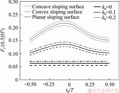
Figure 9 Effect of t0/T and kh on normalized reinforcement force considering three facing profiles
5.2 Effect of non-uniform soil strength parameters
As highlighted earlier, the non-uniformity of soil strength parameters is accounted for using the proposed approach. The significance of soil cohesion in improving slope capacity is substantiated in Figure 10 where the cohesion at slope toe surface c0 increases from 0 to 20 kPa and ch at slope crest is kept as a constant. As expected, the geosynthetic reinforcement force required decreases sharply with the increase of c0. An increased soil cohesion aids to provide more additional resistance to incipient failure, and hence less dependent on the reinforcement of geosynthetics. Similar as before, a steep slope with a concave facing profile has a larger capacity to prevent the occurrence of landslides. It is highlighted that the use of average soil cohesion tends to overestimate the kinematic solution of reinforcement force in non-uniform soil strata.
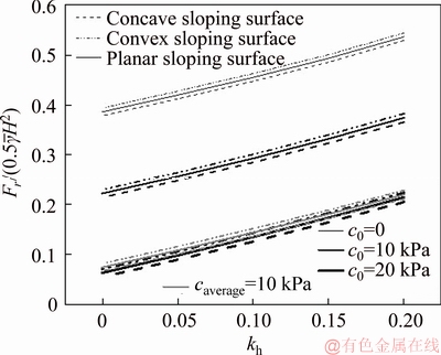
Figure 10 Effect of non-uniform soil cohesion c0 on normalized reinforcement force considering three facing profiles
Within the scope of MC failure criterion, the soil friction angle is vital in upper bound analysis. This angle determines the failure shape of c-�� soil slopes, with a log-spiral detaching surface which is only suited for a constant-angle case. In an effort to consider non-uniform profiles of friction angle, the discretization technique is developed. Apart from this, this angle also plays a decisive role in calculation of internal rate of work. Assuming the friction angle is linearly increased from ��h at slope crest surface to ��0 at slope toe, Figure 11 presents the effect of angle ��0 on kinematic solution of Fr. A significant decrement in normalized ratio  is produced with the increase of angle ��0. The increasing kh yields the opposite consequence. Note that the reinforcement force required is proved to be overly conservative when using an arithmetic average value of non-uniform soil friction angles only.
The critical failure surface under each scenario can be readily plotted with the use of discretization technique. As the soil friction angle is a sensitive parameter, its effect on the yield sliding surface is illustrated in Figure 12. Three cases, ��0 =��h=10o, ��0=��h=20��, and ��0=30��, ��h=10��, are discussed herein. Under the same earthquake, a greater failure area is induced for the constant friction angle increasing from 10�� to 20��. The latter two cases are compared to show the effect of non-homogeneity of friction angle on the failure surface. It is seen that apart from a slightly larger failure area induced with average values, the major difference exists in the shape of sliding surface, which is attributed to the non-uniform soil friction angles used along depth in the point generation based on the associated flow rule.
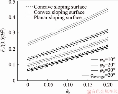
Figure 11 Effect of non-uniform soil friction angle ��0 on normalized reinforcement force considering three facing profiles
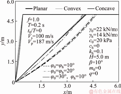
Figure 12 Critical sliding surface considering non- uniformity of soil friction angles and three facing profiles
6 Concluding remarks
This study presents a procedure for seismic analysis of geosynthetic-reinforced steep slopes. In order to assure stability of steep slopes, a geosynthetic type, geogrids or geotextile, is adopted to provide additional resistance. The main work of this study lies in the determination of geosynthetic reinforcement force required from the perspective of plasticity energy. A curved sloping surface including concave, convex and planar profiles and non-uniform soil properties, such as soil unit weight, cohesion and friction angle, can be accounted for. The pseudo-dynamic approach is used to represent the time- and space-dependent seismic shaking. However, the above mentioned cases cannot be readily considered in conventional upper bound analysis. The proposed approach using discretized kinematic analysis is adopted to overcome these shortcomings with ease. Thereof, the discretization technique is proposed to generate a kinematically admissible failure mechanism where non-uniform soil friction angles at different depths are considered based on the associated flow rule. The work rate calculations are performed from elementary analysis which aids to account for complicated scenarios. Finally, the kinematic solution of geosynthetic reinforcement force is formulated based on the work rate-based balance equation. After optimizing the objective function, the optimal upper bound solution is sought under given parameters. The main research findings include:
Slopes with concave facing profiles have a larger capacity than planar and convex to resist ground shaking, and its contribution to slope stability is dependent upon the degree of curved surface.
Use of arithmetic average value in soil cohesion and friction angle overestimates the reinforcement force required in non-uniform soil strata.
The dynamic characteristics of horizontal and vertical accelerations have an effect on prediction of reinforcement force to varying degree. It is likely to yield more reliable solutions with the pseudo-dynamic approach when compared to the simple pseudo-static.
References
[1] CHEN W F. Limit analysis and soil plasticity [M]. Amsterdam: Elsevier, 1975.
[2] XU J S, YANG X L. Seismic stability of 3D soil slope reinforced by geosynthetic with nonlinear failure criterion [J]. Soil Dynamics and Earthquake Engineering, 2019, 118: 86-97.
[3] LI Y X, YANG X L. Soil-slope stability considering effect of soil-strength nonlinearity [J]. International Journal of Geomechanics, 2019, 19(3): 04018201.
[4] LI Z W, YANG X L. Kinematical analysis of active earth pressure considering tension crack, pore-water pressure and soil nonlinearity [J]. KSCE Journal of Civil Engineering, 2019, 23(1): 56-62.
[5] ZHANG J H, WANG W J, ZHANG D B, ZHANG B, MENG F. Safe range of retaining pressure for three- dimensional face of pressurized tunnels based on limit analysis and reliability method [J]. KSCE Journal of Civil Engineering, 2018, 22(11): 4645-4656.
[6] ZHANG D B, JIANG Y, YANG X L. Estimation of 3D active earth pressure under nonlinear strength condition [J]. Geomechanics and Engineering, 2019, 17(6): 515-525.
[7] QIN C B, CHIAN S C. New perspective on seismic slope stability analysis [J]. International Journal of Geomechnics, 2018, 18(7): 06018013.
[8] QIN C B, CHIAN S C. Kinematic stability of a two-stage slope in layered soils [J]. International Journal of Geomechnics, 2017, 17(9): 06017006.
[9] CHEN W F, LIU X L. Limit analysis in soil mechanics [M]. Amsterdam: Elsevier, 1990.
[10] MOLLON G, DIAS D, SOUBRA A H. Rotational failure mechanisms for the face stability analysis of tunnels driven by a pressurized shield [J]. International Journal for Numerical and Analytical Methods in Geomechanics, 2011a, 35: 1363-1388.
[11] QIN C B, CHIAN S C, DU S Z. Revisiting seismic slope stability: intermediate or below-the-toe failure? [J]. G��otechnique, 2019, https://doi.org/10.1680/jgeot.18.T.001.
[12] QIN C B, CHIAN S C. Kinematic analysis of seismic slope stability with a discretization technique and pseudo-dynamic approach: a new perspective [J]. G��otechnique, 2018, 68(6): 492-503.
[13] BASHA B M, BABU G L S. Seismic reliability assessment of internal stability of reinforced soil walls using the pseudo-dynamic method [J]. Geosynthetics International, 2011, 8(5): 221-241.
[14] NIMBALKAR S S, CHOUDHURY D, MANDAL J N. Seismic stability of reinforced-soil wall by pseudo-dynamic method [J]. Geosynthetics International, 2006, 13(3): 111-119.
[15] CHOUDHURY D, KATDARE A. New approach to determine seismic passive resistance on retaining walls considering seismic waves [J]. International Journal of Geomechanics, 2013, 13(6): 852-860.
[16] NIAN T K, CHEN G Q, LUAN M T, YANG Q, ZHENG D F. Limit analysis of the stability of slopes reinforced with piles against landslide in nonhomogeneous and anisotropic soils [J]. Canadian Geotechnical Journal, 2008, 45: 1092-1103.
[17] QIN C B, CHIAN S C, WANG C Y. Kinematic analysis of pile behavior for improvement of slope stability in fractured and saturated Hoek-Brown rock masses [J]. International Journal for Numerical and Analytical Methods in Geomechanics, 2017, 41: 803-827.
[18] LING H I, LESHCHINSKY D, PERRY E B. Seismic design and performance of geosynthetic-reinforced soil structures [J]. Geotechnique, 1997, 47(5): 933-952.
[19] MICHALOWSKI R L. Limit analysis in stability calculations of reinforced soil structures [J]. Geotextiles and Geomembranes, 1998a, 16: 311-331.
[20] MICHALOWSKI R L. Soil reinforcement for seismic design of geotechnical structures [J]. Computers and Geotechnics, 1998b, 23: 1-17.
[21] AUSILIO E, CONTE E, DENTE G. Seismic stability analysis of reinforced slopes [J]. Soil Dynamics and Earthquake Engineering, 2000, 19: 159-172.
[22] ESKANDARINEJAD A, SHAFIEE A H. Pseudo-dynamic analysis of seismic stability of reinforced slopes considering non-associated flow rule [J]. Journal of Central South University of Technology, 2011, 18: 2091-2099.
[23] VAHEDIFARD F, SHAHROKHABADI S, LESHCHINSKY D. Geosynthetic-reinforced soil structures with concave facing profile [J]. Geotextiles and Geomembranes, 2016, 44: 358-365.
[24] FERREIRA F B, TOPA GOMES A, VIEIRA C S, LOPES M L. Reliability analysis of geosynthetic-reinforced steep slopes [J]. Geosynthetics International, 2016, 23(4): 301-315.
[25] JAVANKHOSHDEL S, BATHURST R J. Deterministic and probabilistic failure analysis of simple geosynthetic reinforced soil slopes [J]. Geosynthetics International, 2017, 24(1): 14-29.
[26] QIN C B, CHIAN S C. Pseudo-static/dynamic solutions of required reinforcement force for steep slopes using discretization-based kinematic analysis [J]. Journal of Rock Mechanics and Geotechnical Engineering, 2018, https:// doi.org/10.1016/j.jrmge.2018.10.002.
[27] QIN C B, CHIAN S C. Seismic stability of geosynthetic- reinforced walls with variable excitation and soil properties: A discretization-based kinematic analysis [J]. Computers and Geotechnics, 2018, 102: 196-205.
[28] SHAHGHOLI M, FAKHER A, JONES C J F P. Horizontal slice method of analysis [J]. Geotechnique, 2001, 51(10): 881-885.
(Edited by HE Yun-bin)
���ĵ���
�������ӹ̵������Ͷ����ڵ������Ļ����Է���
ժҪ�����IJ��û��������������˶����ڵ���������ά�����ȶ������������ӹ����������漰���Ӽ��㣬���������������Ƶ�����Ҫ����ƽ���ͱ��¡��������Ȼ�����й㷺�����ŵ������ͱ��£������ǵ��������������ͷǾ��ʱ��£���ͳ�������������Կ������ȶ��ԡ�Ϊ�˽���������⣬�������Ȳ�����ɢ��������һ����ɢ���ƻ����ƣ����������ƻ�����ֽ�ɲ�ͬ����ɲ��֣�Ȼ��ͨ����Ԫ�����������������ӹ�����������ص��ⲿ�����������ʺ����ܺ�ɢ�����в������������ʾ��ʱ��Ϳռ�仯�ĺ����������ٶȡ����ͨ������ƽ�ⷽ�̻���������ӹ������⣬�������˸����ض��������ӹ̶������ܵ�Ӱ�졣
�ؼ��ʣ������������������ɢ���Ļ���������������������
Received date: 2018-11-19; Accepted date: 2019-03-06
Corresponding author: QIN Chang-bing, PhD Candidate; Tel: +86-13789900956; E-mail: changbingqin@u.nus.edu; ORCID: 0000- 0002-9959-1087
Abstract: A procedure of kinematic analysis is presented in this study to assess the reinforcement force of geosynthetics required under seismic loadings, particularly for steep slopes which are hardly able to maintain its stability. Note that curved sloping surfaces widely exist in natural slopes, but existing literatures were mainly focusing on a planar surface in theoretical derivation, due to complicated calculations. Moreover, the non-uniform soil properties cannot be accounted for in conventional upper bound analysis. Pseudo-dynamic approach is used to represent horizontal and vertical accelerations which vary with time and space. In an effort to resolve the above problems, the discretization technique is developed to generate a discretized failure mechanism, decomposing the whole failure block into various components. An elementary analysis permits calculations of rates of work done by external and internal forces. Finally, the upper bound solution of the required reinforcement force is formulated based on the work rate-based balance equation. A parametric study is carried out to give insights on the implication of influential factors on the performance of geosynthetic-reinforced steep slopes.
