
J. Cent. South Univ. (2016) 23: 2429-2442
DOI: 10.1007/s11771-016-3302-y

Study on LQR control algorithm using superelement model
XU Qiang(��ǿ), CHEN Jian-yun(�½���), LI Jing(�), YUAN Chen-yang(Է����), ZHAO Chun-feng(�Դ���)
School of Civil and Hydraulic Engineering, Dalian University of Technology, Dalian 116023, China
 Central South University Press and Springer-Verlag Berlin Heidelberg 2016
Abstract:
The conventional linear quadratic regulator (LQR) control algorithm is one of the most popular active control algorithms. One important issue for LQR control algorithm is the reduction of structure��s degrees of freedom (DOF). In this work, an LQR control algorithm with superelement model is intended to solve this issue leading to the fact that LQR control algorithm can be used in large finite element (FE) model for structure. In proposed model, the Craig-Bampton (C-B) method, which is one of the component mode syntheses (CMS), is used to establish superelement modeling to reduce structure��s DOF and applied to LQR control algorithm to calculate Kalman gain matrix and obtain control forces. And then, the control forces are applied to original structure to simulate the responses of structure by vibration control. And some examples are given. The results show the computational efficiency of proposed model using synthesized models is higher than that of the classical method of LQR control when the DOF of structure is large. And the accuracy of proposed model is well. Meanwhile, the results show that the proposed control has more effects of vibration absorption on the ground structures than underground structures.
Key words:
1 Introduction
Vibration control of structures has attracted much attention during the last two decades. It will continue to be a vigorous region of study due to the need to protect structures against strong earthquakes and winds. The various vibration control strategies, applied to protect structure subjected to dynamic loads, can be classified as active, passive, hybrid and semi-active control. Active control methods are effective for a wide frequency range as well as for transient vibrations. And the optimal LQR control algorithm is the one of the most popular active control algorithms. Many studies about the control algorithm have been made. LIU et al [1] made study on the robust property of LQR. HUI [2] developed a distributed LQR theory for discrete-time systems to design optimal controllers for discrete-time coupled systems. TAO et al [3] described the LQR control algorithm in detail and proposed the parallel distributed fuzzy LQR control algorithm. TARAPADA and DEBABRATA [4] proposed genetic algorithm based on LQR control algorithm to make optimal vibration control of smart fiber reinforced polymer composite shell structures. BASU and NAGARAJAIAH [5] proposed a modified form of the conventional LQR control algorithm using the information derived from the wavelet analysis of the response of structure. POODEH et al [6] employed control methods to control buck converters by LQR controllers as well as optimal locating of the poles by genetic algorithm. POURZEYNALI et al [7] proposed the fuzzy logic controller to develop LQR control algorithm to handle the uncertain, as well non-linear phenomena. JIANG et al [8] developed LQR control to enhance the effect of control. TODOROV et al [9] developed LQR control algorithm for locally-optimal feedback control of nonlinear stochastic systems subject to control constraints. TAYFUN and STEPHEN [10] studied the optimal control of general nonlinear controlled systems based on LQR control algorithm. SAM et al [11] presented a new robust strategy in controlling the active suspension system based on LQR control algorithm. ADELI and KIM [12] presented a hybrid feedback-least mean square algorithm for control of structures based on LQR control algorithm. KIM and ADELI [13] proposed a method based on LQR control algorithm to induce the effects of parameter uncertainty of structure. VADIGEPALLI [14] studied the multirate distributed and decentralized method to evaluate LQR control. KIM et al [15] studied LQR control to reduce the synchronous error of controllers. TRINDADE et al [16] presented the design and analysis of the piezoelectric active control of damped sandwich beams improved by LQR control algorithm. LI et al [17] studied the active control algorithms in buildings excited by strong wind force based on LQR control algorithm. From above studies, it is known that one important issue for LQR control algorithm is that large structure��s DOF will lead to the fact that the method cannot be used. Thus, the reduction of structure��s DOF is important.
Dynamic substructuring (DS) is a family of methods based on the main idea of ��divide and conquer��, by dividing a large structure into smaller and simpler substructures. Each substructure can independently compute the dynamic behavior, which greatly improves the efficiency. DS methods are often classified into three distinct families, the frequency based substructuring (FBS) methods, CMS techniques and impulse based substructuring (IBS). And many works about these families of DS have been made. BOER et al [18] proposed a nonlinear two-node superelement based on CMS technique for the modeling of flexible complex-shaped links for use in multibody simulations. PAUL and DANIEL [19] developed IBS, which is an extension to the normal time integration methods used for obtaining the time responses of FE models. FEHR and EBERHARD [20] used CMS technique to reduce the flexible body��s DOF. MOURELATOS [21] presented FBS with Ritz vectors for predicting the dynamic response of structure. ALBERTO [22] presented a new CMS technique of substructuring methods for flexible multibody analysis. From above studies, it is known that CMS technique is a powerful tool to solve DS.
Based on the analysis above, a LQR control algorithm with CMS technique is proposed to solve the control problems of large structure. The proposed model combines the advantages of LQR control algorithm and CMS technique. And it has higher computational efficiency than classical LQR control algorithm. And the accuracy of proposed model is also well. Then, the proposed model is introduced in detail hereafter.
2 Optimal LQR control
The classical LQR method has been described by many researchers. And the method will be described in detail hereafter.
The equations of motion of a discretized dynamic complex structure with controllers are
 (1)
(1)
 (2)
(2)
in which

 (3)
(3)
where Z is the state vector; A, B, D, C0, B0 and D0 are coefficient matrices, respectively; U is the control action; F is the external forces; Y is the output vector. M, C and K are mass, damping and stiffness matrix of complex structure, respectively; Vector u(t) is the DOF; and
and  are its respective time derivatives; Ds and Bs are the matrices describing the position of the external forces and the controllers, respectively.
Based on the optimal LQR control technique, a quadratic cost function J is given by
 (4)
(4)
in which
 (5)
(5)
where R is positive definite weight matrices; Q is a positive semi-definite weight matrix; �� and �� are parameters for LQR controllers.
Then, the optimization problem can be proposed for the control system.
 (6)
(6)
in which
 (7)
(7)
where �� is the Lagrangian multiplier.
The Riccati equation can be expressed as
 (8)
(8)
And solving Eq. (8), P is obtained and the optimal control input U* can be obtained as
 (9)
(9)
in which
 (10)
(10)
where G is a Kalman gain matrix.
When using the optimal LQR control technique, the number of DOFs of complex structure plays very important role in calculating time. And sometimes the optimal LQR control technique cannot be used when the number of DOFs of complex structure is very large. Thus, the model reduction techniques need to be used to decrease the calculated number of DOFs of complex structure. This method will be described hereafter.
3 Superelement model: C-B method
CMS method is often used to analyze for large or complex structures. And one very popular CMS method often used today is the C-B method. NORTIER et al [23] introduced the method. And it will be described in detail hereafter.
The equation of motion of a discretized dynamic substructure is
 (11)
(11)
where Ms, Cs and Ks are mass, damping and stiffness matrices of substructure, respectively; Vector us(t) is the DOF;  and
and  are its respective time derivatives; f s(t) is the external force vector; gs(t) is the vector of the connection forces with other substructures; b denotes the part belonging the interface of substructure; i denotes the internal part of substructure.
In order to establish a good approximation for the internal DOF, the C-B method divides the response of the internal DOF into a static and a dynamic part:
 (12)
(12)
where is the static part;
 is the dynamic part.
From the second line of Eq. (11), the C-B method sets  and takes
  and
and  to zero in order to neglect the inertia forces. And the static response can be given by
 (13)
(13)
where ��i are the so-called static constraint modes. Each column of ��i is the static response of  to a unit displacement (DIS) of an interface DOF, while the other interface DOFs are constrained. The number of static modes is the same as the number of boundary DOFs.
The C-B method takes the force acting on the internal DOF to zero and restrains the interface DOF. By these steps, the dynamic responsecan be also obtained from the second line of Eq. (11). The dynamic responseis approximately used a superposition of a truncated number of vibration modes:
 (14)
(14)
where matrix ��i is a truncated collection of so-called fixed interface vibration modes; ��i is a vector which consists of the corresponding modal amplitudes. ��i can be obtained from the eigenproblem (15):
 (15)
(15)
where ��i, n is a single fixed interface vibration mode with unit modal mass, and ��i,n is corresponding eigenfrequency.
Then, an approximation for the response of the internal DOF is
 (16)
(16)
Due to setting the force acting on the internal DOF to zero, the accuracy of the response is dependent on the accuracy of the static constraint and fixed interface vibration modes describing the response to the force. The reduction matrix of the C-B method is obtained as
 (17)
(17)
where RCB is the reduction matrix. And Eq. (11) can be rewritten as
 (18)
(18)
in which
 (19)
(19)
 (20)
(20)
 (21)
(21)

 (22)
(22)
 (23)
(23)
where  is a diagonal matrix containing the fixed interface eigenfrequencies. One of the advantages of the C-B method is that it is easy assembly with other substructures.
From above steps, the mass, damping and stiffness matrix of substructure can form superelement which only contains nodes belonging to the interface of substructure. And this method can effectively reduce calculated number of DOFs of complex structure. And the optimal LQR control technique can be used in large structure based on the C-B method.
4 Improved LQR method based on superelement model
The main idea of the application of C-B method to LQR method is firstly dividing the complex structures into two parts: the FE models of near region of controllers and the superelement models of substructures for other region based on C-B method. Then, the LQR method is used to calculate the control forces. Finally, the control forces are applied to the complex structures to calculate the response of the complex structures.
For instance, consider two substructures.
 (24)
(24)
 (25)
(25)
where f��s(t) is the external force vector after transformation; g��s(t) is the vector of the connection forces with other substructures after transformation.
If we only pay attention to substructure 1, we can take reduce scale of ��i2. Thus, we can synthesize K and M of substructure to reduce DOF of structure. And we can obtain the coefficient matrix for concerned region s1 as
 (26)
(26)
 (27)
(27)
 (28)
(28)
 (29)
(29)
Then, we can solve the follow equation:

 (30)
(30)
And Pb is obtained and the optimal control input  can be obtained as
 (31)
(31)
and
 (32)
(32)
Because
 (33)
(33)
And the whole structure is

 (34)
(34)
The flow chart of proposed model is described in Fig. 1.
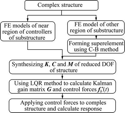
Fig. 1 Flow chart of proposed model
5 Numerical example
5.1 Verification for proposed controlled model
5.1.1 Description of model of a three-dimensional (3D) beam
The firstly analyzed object is a 3D beam. The section of beam is 2 m��2 m. And the shear-center is the same as the centroid of section. The length of the beam is 12 m. The elastic modulus of material is 20 GPa. The Poisson ratio of material is 0.167. The density of material is 2000 kg/m3. The damping ratio of structure is 0.05. The parameters for LQR controllers are ��=2.1872, ��=1��10-7. The positions of controllers are at 11 m and 12 m and the controlled directions are x and z two horizontal directions. Four controllers are applied. The first and second ones control x and z directions at 12 m, respectively. The third and fourth ones control x and z directions at 11 m, respectively. The beam is meshed to 12 3D-beam-elements of two nodes. The size of elements of model is 1 m. All DOFs of nodes at bottom of beam are constrained. And the calculated steps are shown in Fig. 2. And the seismic load is considered. Seismic load is loaded in the way of inertia force. The design peak ground acceleration (PGA) is 3 m/s2. And the seismic ground accelerations are shown in Fig. 3.
5.1.2 Results and discussion for Example 1
A modal analysis is firstly made. The first order frequencies of synthesized and un-synthesized models are 6.9838 Hz and 6.9602 Hz, respectively. From the results, it can be observed that the difference of first order frequencies of un-synthesized and synthesized models is 0.0236 Hz, which is far less than the first order frequencies. The calculated time of proposed model and classical LQR model is 0.4220 s and 4.5250 s, respectively. And the calculated time of proposed model is 9.32% of that of LQR model. Because the freedom of substructure A is 18, the scale of matrix mainly used to calculate the optimal control of proposed model is 72��72. But the freedom of whole structure is 78 and the scale of matrix mainly used to calculate the optimal control of LQR model is 312��312. The theoretical computational complexity of model is O(n3), in which n is the number of rows or columns of square matrix. The theoretical computational complexity is usually used to characterize calculated time of models. Thus, the calculated time of proposed model and LQR model is O(723) and O(3123), respectively. And these reasons slow down the calculated time of LQR model. From what has been discussed above, it shows that the computational efficiency of proposed model using synthesized models is higher.
And the controlled forces of controllers are shown in Fig. 4. The maximum and minimum values of difference of the controlled forces between using proposed model and classical LQR model are shown in Fig. 5. And the most difference using different models is approximately 3 kN, which is far less than the peak of controlled forces. The DISs at top of beam are shown in Fig. 6 and Table 1. From the results, it can be observed that the DIS at top of beam using controllers is approximately half of that no using controllers and the maximum reduction can reach 60.29% by proposed model and 65.15% by classical LQR model, which shows that the damped effects of controllers are obvious. It can also be observed that the controlled DISs are almost the same between using proposed model and using classical LQR model. The von Mises stresses of beam are shown in Fig. 7. From the results, it can be observed that the stresses will be obviously deduced when using controllers. And the stresses of beam using proposed model are slightly less than that using classical LQR model. From above results, it shows that the accuracy of proposed model is well.
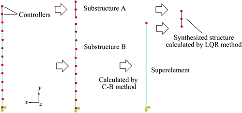
Fig. 2 Calculated steps of proposed controlled model for beam
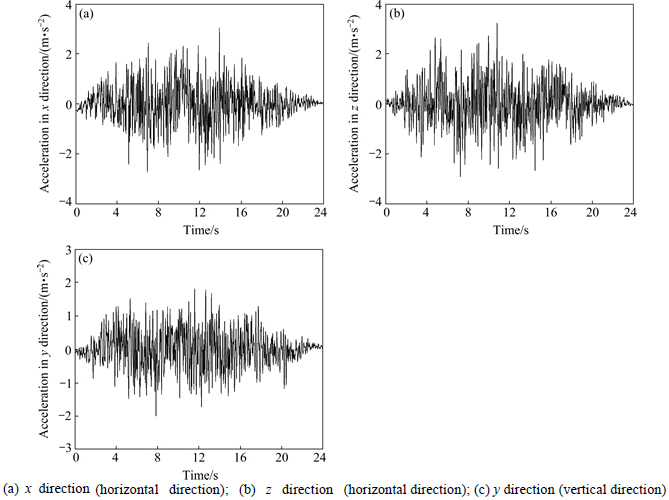
Fig. 3 Seismic ground acceleration:
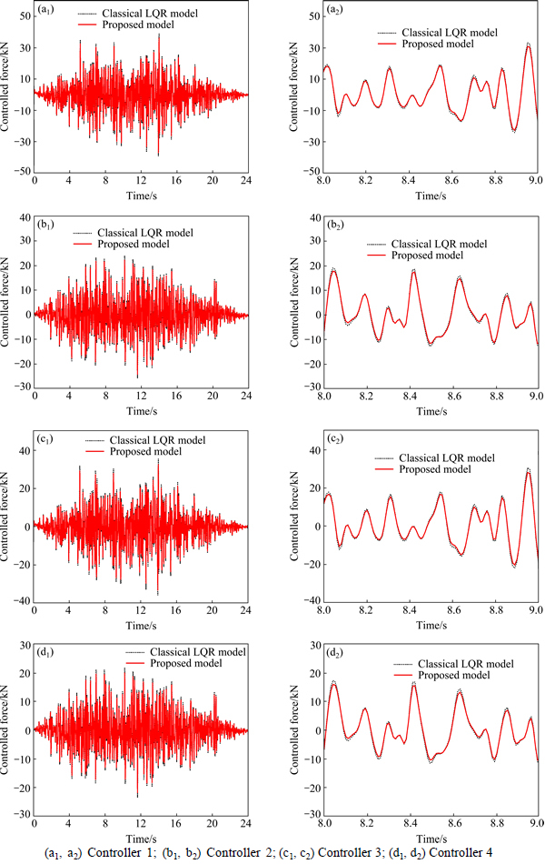
Fig. 4 Controlled forces of controllers using un-synthesized and synthesized models:
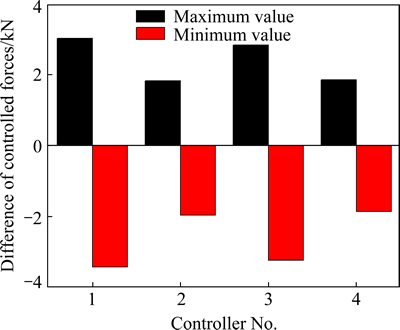
Fig. 5 Maximum and minimum values of difference of controlled forces between using unsynthesized and using synthesized models
5.2 Proposed controlled model applied in underground structure
5.2.1 Description of model of an underground structure
The secondly analyzed object is a two-dimensional (2D) underground structure [24]. It corresponds to the Zhujiang Road subway station in Nanjing, China. The underground structure has a rectangular cross section and was built by the cut-and-cover method. The station has two stories and three spans. The structure is located on alluvial soils deposited by the Yangtze River. The size and mesh of underground structure are shown in Fig. 8. The depth of overburden of the underground structure is 2 m. The depth of soil is 50 m. The size of mesh of soil is approximately 3 m. The size of mesh of the wall of the underground structure is approximately 0.5 m. The size of beams and columns of subway station is approximately 5 m. The outside of the underground structure and soil around are meshed by plane strain elements of four nodes. And the inside of the underground structure is meshed by 2D beam element of two nodes. The elastic modulus of underground structure and soil around are 20 GPa and 0.67 GPa, respectively. The Poisson ratio of underground structure and soil around are 0.167 and 0.3, respectively. The density of underground structure and soil around are both 2000 kg/m3. The damping ratio of structure is 0.05. The parameters for LQR controllers ��=2.2346, ��=1��10-7. The positions and controlled DOFs of controllers are also shown in Fig. 8. Four controllers are applied. The boundary conditions are also shown in Fig. 8. And the seismic load is considered. And the seismic ground accelerations are adopted according to Fig. 3(a) and (c). Seismic load is loaded in the way of inertia force. The PGA is also 3 m/s2. And the calculated steps of proposed controlled model for underground structure are shown in Fig. 9.
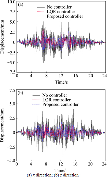
Fig. 6 DIS at top (12 m) of beam:
Table 1 Maximum and minimum values of DIS at top of beam

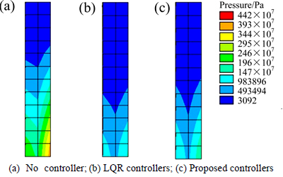
Fig. 7 von Mises stress of beam (Pa):
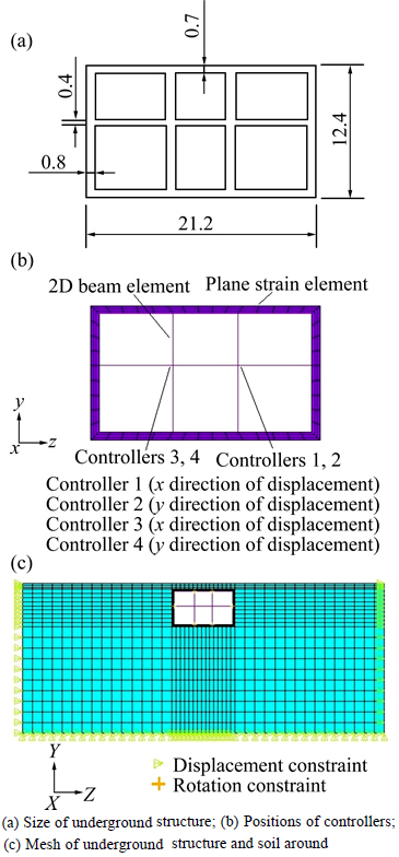
Fig. 8 Model of underground structure:
5.2.2 Results and discussion for Example 2
The DISs at the position of controllers are shown in Fig. 10 and Table 2. From the results, it can be observed that the DISs at the position of controllers are obviously reduced. The maximum reduction can reach 31.606% by proposed model, which shows the damped effects of DISs of proposed control are obvious. And it also can be observed that the damped effects of DISs in y direction are better than that in x direction. The von Mises stresses of underground structure are shown in Fig. 11. From the results, it can be observed that the stresses will be slightly deduced when using proposed control. From above results, it shows that the proposed control has effects on controlling the DISs of underground structure and slightly deduces the stresses of underground structure. And because the proposed model deduces the calculated time and gives similar computational accuracy compared to LQR model, it can provide real-time control for controllers and reduce the delay of controlled time.
5.3 Proposed controlled model applied in AP1000 shield building
5.3.1 Description of model of an AP1000 shield building
The AP1000 system is one of the most popular units among the generation III+ nuclear power plants. The thirdly analyzed object is a 3D AP1000 shield building.
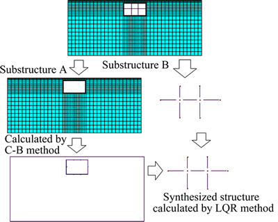
Fig. 9 Calculated steps of proposed controlled model for underground structure
Table 2 Maximum and minimum values of DIS of underground structure
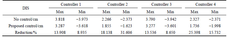

Fig. 10 DIS at position of controllers by no controlling and proposed controlling for underground structure:
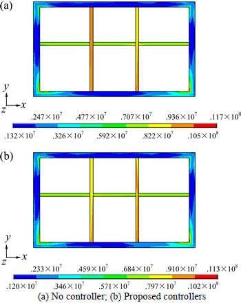
Fig. 11 von Mises stress of underground structure (Unit: Pa):
The structure is meshed by shell elements of four nodes. The thickness of shell is 1.1 m. The mesh and boundary conditions of AP1000 shield building, the positions and controlled DOFs of controllers, the calculated steps of proposed controlled model are all shown in Fig. 12. All DOFs of nodes at bottom of AP1000 shield building are all constrained. The size of mesh of AP1000 shield building is approximately 1 m. The elastic modulus of material is 33.5 GPa. The Poisson ratio of material is 0.2. The density of material is 2300 kg/m3. The damping ratio of structure is 0.05. The parameters for LQR controllers are ��=1.0880, ��=1��10-8. And the seismic load is considered. And the seismic ground accelerations are the same as the example 1. The PGA is also 3 m/s2.
5.3.2 Results and discussion for Example 3
The DISs at the position of controllers are shown in Figs. 13-14 and Table 3. From the results, it can be observed that the DISs at the position of controllers areobviously reduced. The maximum value of reduction can reach 41.212% by proposed model, which shows that the damped effects of DISs of proposed control are obvious. The von Mises stresses of AP1000 shield building are shown in Fig. 14. The maximum value of the von Mises stresses is 6.10 MPa for no control but 5.86 MPa for proposed control. And the distributions of stresses are changed.
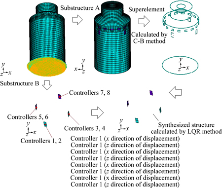
Fig. 12 Calculated steps of proposed controlled model for AP1000 shield building
Using proposed control, the stresses at bottom of AP1000 shield building are changed from approximately 6 MPa to 4 MPa, which shows that the proposed control can effectively reduce the vibration and then reduce the stresses. However, the control can also cause stress concentration at the positions of controllers. The effects can be reduced by increasing the contact area between controllers and AP1000 shield building. From above results, it shows that the proposed control has effects on controlling the DISs of AP1000 shield building and effectively deduces the stresses of AP1000 shield building. It shows that the proposed control has more effect on the ground structures than underground structures. Because AP1000 shield building has higher safety requirements than other structures, it needs real- time and precise control when earthquake occurs. In other words, it needs less calculated time and high computational efficiency. And due to less calculated time and high computational accuracy of the proposed model, the proposed model for controllers is more suitable for AP1000 shield building.
Table 3 Maximum and minimum values of DIS of AP1000 shield building

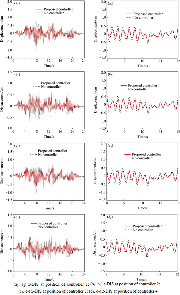
Fig. 13 DIS by no controllers and proposed controllers for AP1000 shield building:
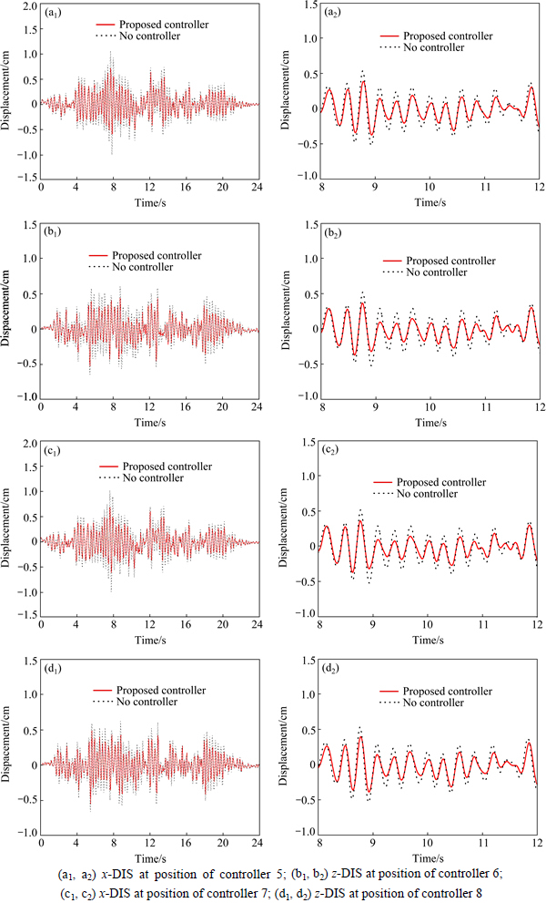
Fig. 14 DIS by no controllers and proposed controllers for AP1000 shield building:
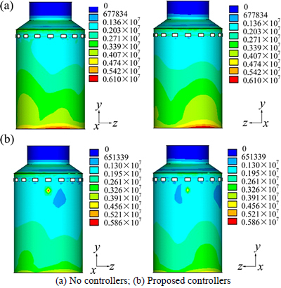
Fig. 15 von Mises stress of AP1000 shield building (Unit: Pa):
6 Conclusions
1) The computational efficiency of proposed model using synthesized models is higher than that of the classical method of LQR control.
2) The controlled DISs are almost the same between using proposed model and the classical method of LQR control. It proves that the accuracy of proposed model is well.
3) The proposed control has effects on controlling the DISs of underground structure and AP1000 shield building. The proposed control can effectively deduce the stresses of AP1000 shield building but slightly deduce the stresses of underground structure. Thus, the proposed control has more effect on the ground structures than underground structures.
4) The proposed control can cause stress concentration at the positions of controllers for AP1000 shield building. The effects can be reduced by increasing the contact area between controllers and AP1000 shield building.
5) Indeed, some simple single models of underground structure and AP1000 shield building are considered as the underground project and nuclear power project are system engineering. Thus more studies for proposed model for controlling vibration of the system engineering should be made in the future.
References
[1] LIU X D, WU Y J, ZHANG Y, XIAO S. A control method to make lqr robust: A planes cluster approaching mode [J]. International Journal of Control, Automation, and Systems, 2014, 12(2): 302-308.
[2] HUI Q. Distributed semistable LQR control for discrete-time dynamically coupled systems [J]. Journal of the Franklin Institute, 2012, 349: 74-92.
[3] TAO C W, TAUR J S, CHEN Y C. Design of a parallel distributed fuzzy LQR controller for the twin rotor multi-input multi-output system [J]. Fuzzy Sets and Systems, 2010, 161: 2081-2103.
[4] TARAPAD A R, DEBABRATA C. Optimal vibration control of smart fiber reinforced composite shell structures using improved genetic algorithm [J]. Journal of Sound and Vibration, 2009, 319(1/2):15-40.
[5] BASU B, NAGARAJAIAH S. A wavelet-based time-varying adaptive LQR algorithm for structural control [J]. Engineering Structures, 2008, 30(9): 2470-2477.
[6] POODEH M B, ESHTEHARDIHA S, KIYOUMARSI A, ATAEI M. Optimizing LQR and pole placement to control buck converter by genetic algorithm [J]. Control, Automation and Systems, 2007, 17/18/19/20: 2195-2200.
[7] POURZEYNALI S, LAVASANI H H, MODARAYI A H. Active control of high rise building structures using fuzzy logic and genetic algorithms [J]. Engineering Structures, 2007, 29(3): 346-357.
[8] JIANG Z, HAN J D, WANG Y C, SONG Q. Enhanced LQR control for unmanned helicopter in hover [J]. Systems and Control in Aerospace and Astronautics, 2006, 6: 1437-1443.
[9] TODOROV E, SAN D C, LI W W. A generalized iterative LQG method for locally-optimal feedback control of constrained nonlinear stochastic systems [J]. American Control Conference, 2005, 1: 300-306.
[10] TAYFUN C, STEPHEN P B. Global optimal feedback control for general nonlinear systems with nonquadratic performance criteria [J]. Systems & Control Letters, 2004, 53(5): 327-346.
[11] SAM Y M, OSMAN J H S, GHANI M R. A class of proportional-integral sliding mode control with application to active suspension system [J]. Systems & Control Letters, 2004, 51(3/4): 217-223.
[12] ADELI H, KIM H. Wavelet-hybrid feedback-least mean square algorithm for robust control of structures [J]. Journal of Structural Engineering, 2004, 130(1): 128-137.
[13] KIM H J, ADELI H. Hybrid feedback-least mean square algorithm for structural control [J] Journal of Structural Engineering, 2004, 130(1): 120-127.
[14] VADIGEPALLI R. A distributed state estimation and control algorithm for plantwide processes [J]. Control Systems Technology, 2003, 11(1): 119-127.
[15] KIM S, CHU B, HONG D, PARK H K. Synchronizing dual-drive gantry of chip mounter with LQR approach [J]. Advanced Intelligent Mechatronics, 2003, 2: 838-843.
[16] TRINDADE M A, BENJEDDOU A, OHAYON R. Piezoelectric active vibration control of damped sandwich beams [J]. Journal of Sound and Vibration, 2001, 246(4): 653-677.
[17] LI Q S, LIU D K, FANG J Q, TAM C M. Multi-level optimal design of buildings with active control under winds using genetic algorithms [J]. Journal of Wind Engineering and Industrial Aerodynamics, 2000, 86(1): 65-86.
[18] BOER S E, AARTS R G K M, MEIJAARD J P, BROUWER D M, JONKER J B. A nonlinear two-node superelement with deformable-interface surfaces for use in flexible multibody systems [J]. Multibody System Dynamics, 2014, 31: 405-431.
[19] PAUL L C V, DANIEL J R. An impulse based substructuring method for coupling impulse response functions and finite element models [J]. Computer Methods in Applied Mechanics and Engineerging, 2014, 275: 113-137.
[20] FEHR J, EBERHARD P. Simulation process of flexible multibody systems with non-modal model order reduction techniques [J]. Multibody System Dynamics, 2011, 25: 313-334.
[21] MOURELATOS Z P. An efficient crankshaft dynamic analysis using substructuring with ritz vectors [J]. Journal of Sound and Vibration, 2000, 238(3): 495-527.
[22] ALBERTO C. Superelements modelling in flexible multibody dynamics [J]. Multibody System Dynamics, 2000, 4: 245-266.
[23] NORTIER B P, VOORMEEREN S N, RIXEN D J. Application of residual vectors to superelement modeling of an offshore wind turbine foundation [J]. Topics in Experimental Dynamics Substructuring and Wind Turbine Dynamics, Conference Proceedings of the Society for Experimental Mechanics Series, 2012, 2: 149-163.
[24] GUO J, CHEN J Y, BOBET A. Influence of a subway station on the inter-story drift ratio of adjacent surface structures [J]. Tunnelling and Underground Space Technology, 2013, 35: 8-19.
(Edited by DENG L��-xiang)
Foundation item: Project(LZ2015022) supported by Educational Commission of Liaoning Province of China; Projects(51138001, 51178081) supported by the National Natural Science Foundation of China; Project(2013CB035905) supported by the Basic Research Program of China; Projects(DUT15LK34, DUT14QY10) supported by Fundamental Research Funds for the Central Universities, China
Received date: 2015-05-26; Accepted date: 2015-08-09
Corresponding author: XU Qiang, PhD, Associate Professor; Tel: +86-13478480295; E-mail: xuqiang528826@dlut.edu.cn
Abstract: The conventional linear quadratic regulator (LQR) control algorithm is one of the most popular active control algorithms. One important issue for LQR control algorithm is the reduction of structure��s degrees of freedom (DOF). In this work, an LQR control algorithm with superelement model is intended to solve this issue leading to the fact that LQR control algorithm can be used in large finite element (FE) model for structure. In proposed model, the Craig-Bampton (C-B) method, which is one of the component mode syntheses (CMS), is used to establish superelement modeling to reduce structure��s DOF and applied to LQR control algorithm to calculate Kalman gain matrix and obtain control forces. And then, the control forces are applied to original structure to simulate the responses of structure by vibration control. And some examples are given. The results show the computational efficiency of proposed model using synthesized models is higher than that of the classical method of LQR control when the DOF of structure is large. And the accuracy of proposed model is well. Meanwhile, the results show that the proposed control has more effects of vibration absorption on the ground structures than underground structures.
