
Trans. Nonferrous Met. Soc. China 24(2014) 996-1003
TLP bonding of dissimilar FSX-414/IN738 system with MBF80 interlayer: Prediction of solid/liquid interface location
B. ABBASI KHAZAEI, G. ASGHARI, R. BAKHTIARI
Department of Materials Science and Engineering, Razi University, Kermanshah, 67147-54374, Iran
Received 18 July 2013; accepted 8 October 2013
Abstract:
Isothermal solidification process of a dissimilar transient liquid phase (TLP) bonding of FSX-414/MBF80/IN738 system was simulated by finite difference method. The TLP joint model was divided into two parts and a moving liquid /solid interface model was used for the parts. Diffusion equations were solved for each half of the joints simultaneously up to the end of isothermal solidification. The completion time of isothermal solidification, concentration profiles and position of the solid/liquid interface for each half were calculated. The intersection of the solid/liquid interfaces of two halves was considered the end of isothermal solidification. To obtain some required diffusion data, TLP bonding of FSX-414/MBF80/IN738 was performed at different temperature and time under vacuum atmosphere. The calculated results show good agreement with the experimental results.
Key words:
superalloys; dissimilar TLP bonding; interface location; simulation;
1 Introduction
Transient liquid phase (TLP) bonding is an interesting process in the field of construction and repair of similar and dissimilar structural materials which are difficult to weld. It is applied in aerospace industry, construction and repair of turbine blades, electronics and bonding of superalloys [1-3]. In TLP process a filler material usually has similar composition of base metals, and contains elements such as boron and phosphorus which reduce the melting point. The filler material is inserted between two base materials and the whole assembly is heated to bonding temperature which is defined as being higher than melting temperature of the filler but below that of the substrate material. Because of holding assembly in bonding temperature, the filler material melts and fills the space between the two contact surfaces. During melting of filler material, some parts of the base metals dissolve and solid/liquid interface starts to move and develop the molten zone until local equilibrium occurs at liquid/solid interface. In the next stage, the melting point depressant elements such as boron diffuse to the base metal and the chemical composition of the interface changes and its melting point increases. With increasing of melting point above the local temperature, isothermal solidification begins and the solid/liquid interfaces move toward center of the joint. If holding time at the bonding temperature is sufficient, the interfaces get each other and isothermal solidification will be completed [4-8]. Otherwise, harmful products of eutectic will be produced [9]. Moreover, if the holding time is more than the optimum, the cost of process will increase unnecessarily. Required time to complete isothermal solidification depends on various parameters such as chemical composition of the base metal and filler material, interlayer thickness and bonding temperature [4].
Many efforts have been done to calculate solidification time, concentration profile and position of solid/liquid interface and most of them are limited to the joints with similar materials [10-14]. There are a few reports for the joints with dissimilar materials [4].
Due to widespread application of nickel-based super alloy, many researches about its TLP bonding have been carried out to date. However, there are very few reports about TLP bonding of cobalt-based super alloy FSX-414 [15-17] and so far there is no report about TLP bonding of FSX-414/MBF80/IN738 system. In the present work, a new and simple model for prediction of solid/liquid interface location and isothermal solidification time in TLP bonding of dissimilar system is developed. The model is verified by TLP bonding systems of FSX-414/MBF80/FSX-414 and FSX-414/MBF80/ IN738.
2 Simulation of TLP bonding
2.1 Moving liquid/solid interface model
To calculate the movement of solid/liquid interface in the dissimilar TLP joints, finite difference method with linear elements was used to solve differential equations. Schematic of the joint is shown in Fig. 1.
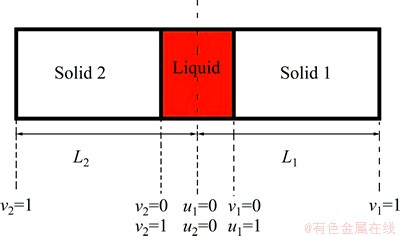
Fig. 1 One dimensional schematic of dissimilar TLP joint
In this model the whole joint including liquid zone was divided into two parts and the simulation was started on each part simultaneously. Solid/liquid interfaces develop and get each other at a position between the liquid zones. The position is unknown and should be calculated. To calculate the position, the trial and error technique was used. At first, middle of the liquid zone was chosen as the position and the isothermal solidification time at the each half of joints was calculated. Whenever difference between two isothermal solidification times is greater than a negligible error, a new position for the interface intersection is obtained. To update the position, an incremental distance from the joint half with more solidification time reduces and is added to the other half. The calculation will stop when difference between the calculated solidification times in two halves becomes smaller than the negligible error. Following assumptions are considered in the calculations:
1) Coefficient of diffusion is independent of concentration in the liquid and solid phases;
2) The mole volume is assumed to be constant;
3) The liquid/solid interface always exhibits a planar geometry;
4) Geometrical symmetry exists at the centerline of the joint.
2.2 Differential equations and discritization
One-dimensional differential equations in a diffusion process with a solid/liquid interface movement are shown as follows [4]:
 (1)
(1)
 (2)
(2)

 (3)
(3)
The discretized equations are extracted in relations of Eqs. (4)-(9). To determine position of the solid/liquid interface in the first and second joint halves, Eqs. (4) and (5) are used as follows:


 (4)
(4)


 (5)
(5)
The solute concentration of the liquid phase can be calculated by Eqs. (6) and (7) in the first and second joint halves, respectively.

 (6)
(6)

 (7)
(7)
To determine the solute concentration of the solid phase in the first and second joint halves, Eqs. (8) and (9) are used respectively.


 (8)
(8)


 (9)
(9)
2.3 Diffusion data
To simulate TLP bonding of FSX-414/MBF-80/ FSX-414 and FSX-414/MBF-80/IN738 systems, some data were required including the bonding temperature, diffusion activation energy (Q) of boron as the melting point depressant element, diffusion constant of boron in the base metal (Do), the initial concentration of boron at the base metal and interlayer, equilibrium concentration of boron at the solid/liquid interface and thicknesses of the interlayer and base metal. The initial concentrations of boron in IN738, FSX-414 superalloys and the interlayer according to chemical composition of the superalloys (Table 1) are 0.009%, 0.006% and 4% in mass fraction (0, 0, 18.13% in mole fraction), respectively. Also, the boron equilibrium concentrations of the materials at the solid/liquid interface are estimated to be 0, 0, 3.6% in mass fraction (0, 0 and 16.87% in mole fraction) respectively by binary phase diagrams of Ni-B and Co-B. Diffusion constant of boron in the liquid phase of each superalloy was considered 5��10-9 m2/s [4]. Diffusion coefficient of boron in a IN738 single crystal superalloy was estimated as 0.14 m2/s [2,4]. To consider grain boundaries effects, the following equation was used [18]:
 (10)
(10)
where Deff is the effective diffusion coefficient, Db is diffusion coefficient in the bulk, �� is grain boundary width, l is the average grain size and Dgb is diffusion coefficient at the boundary. Diffusion activation energy of boron in IN738 superalloy was assumed to be 211 kJ/mol [4].
Since the diffusion constant and diffusion activation energy of boron in FSX-414 superalloys were not available, the diffusion constants of boron in both of superalloys were considered to be same and equal to 0.14 m2/s at single crystal condition. Since diffusion constant of an interstitial atom depends on unit cell parameter in the second order and considering that the unit cells of Co and Ni are same and their unit cell parameters are very closed to each other, so it is suggested and verified by the numerical calculation that the error resulted from these assumptions can be ignored. Using Eq. (10), the effective diffusion coefficient for the polycrystal superalloy was obtained.
To obtain the diffusion activation energy of boron in FSX-414 superalloy, diffusion couples were prepared for FSX-414 superalloy with dimensions of 5 mm��5 mm�� 10 mm. After initial preparation, TLP bonding was performed in a vacuum furnace at 1050, 1075, 1100 and 1150 ��C bonding temperatures for different time, using MBF-80 interlayer with thickness of 50 ��m. Then, the width of the eutectic layer at interface of the joints was measured at least in 5 points by metallographic method. The results are shown in Fig. 2. In Fig. 2, slope of the lines, m, is related to the diffusion activation energy according to Eq. (11) [19]:
 (11)
(11)
where Cs and Cl are concentrations of the melting point depressant element (boron) in the solid and liquid phases, respectively; Vs and Vl are mole volume of the solid and liquid phases, respectively; Q is the diffusion activation energy; D0 and R are constants. Equation (11) can be simplified as follows [19]:
ln m=A-Q/(2RT) (12)
Variation of ln m vs 1/T is shown in Fig. 3. According to this diagram, the diffusion activation energy of boron in the FXS-414 superalloy is obtained as 229 kJ/mol.
Table 1 Chemical composition of IN738, FSX-414 superalloys and MBF-80 interlayer (mass fraction, %)
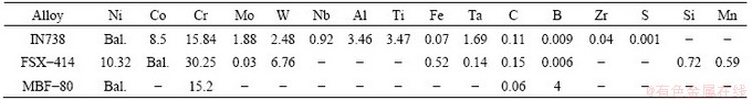
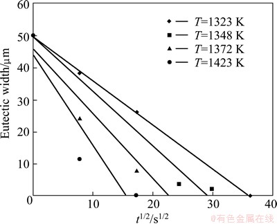
Fig. 2 Variation of square root of holding time t1/2 with eutectic width
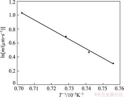
Fig. 3 Linear relationship between ln m and 1/T
3 Results and discussion
3.1 Verifying program
To verify the program, the isothermal solidification time and the solid/liquid interface position in a TLP bonding of CMSX-4/MBF80/IN738 were calculated and compared with the experimental and calculated results by GHONAIM and OJO [20]. The results are shown in Figs. 4 and 5. The model [20] predicted the isothermal solidification time at 1373 and 1403 K bonding temperature for 6.2 and 4.8 h, respectively, whereas the experimental results are about 6-7 h at 1373 K and 5-5.5 h at 1403 K. In the present model, the predicted times of complete isothermal solidification are 6.5 and 4.2 h at 1373 and 1403 K bonding temperatures, respectively. The present model can be acceptable and applied for dissimilar TLP systems.
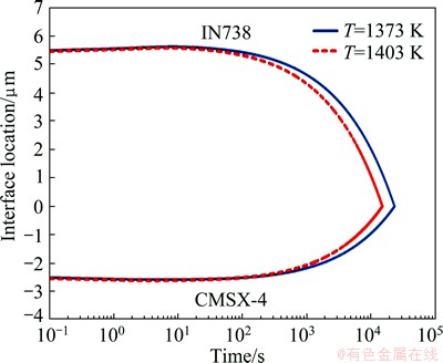
Fig. 4 Predicted solid/liquid interface location in TLP bonding of CMSX-4/MBF80/IN738 by the present model
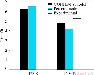
Fig. 5 Obtained isothermal solidification time in TLP bonding of CMSX-4/MBF80/IN738 by the present model, GHONAIM��s model and experiments [20]
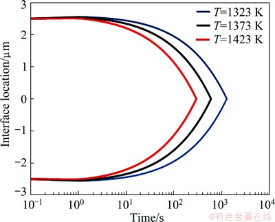
Fig. 6 Predicted solid/liquid interface location in TLP bonding of FSX-414/MBF80/ FSX-414 by the present model
3.2 Simulation
3.2.1 TLP bonding of FSX-414/MBF-80/FSX-414
Figure 6 shows the position of solid/liquid interfaces in TLP bonding of FSX-414/MBF-80/FSX- 414 at temperatures of 1323, 1373 and 1423 K. The curve is fully symmetrical and the location of the solid/liquid interface at the end of isothermal solidification is determined by a point where two branches of the curve get each other. The simulated and experimental results related to completion time of isothermal solidification are compared in Fig. 7. The simulated results show that the solidification isothermal times are 1267, 593 and 293 s at the temperatures of 1323, 1373 and 1423 K, respectively; whereas for the same temperatures, experimental results are 1200, 600 and 300 s, respectively. Microstructure of the FSX-414/MBF-80/ FSX-414 joints made at 1323 K for 10 min is shown in Fig. 8. It is seen that the joint microstructure of the two halves are similar. The eutectic islands, shown by the arrow, were almost formed on the center line of the joints. This confirms the simulation results where the solid/liquid interface location is almost at the center line of the interlayer.
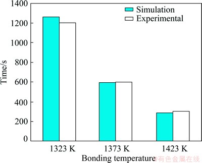
Fig. 7 Isothermal solidification time in TLP bonding of FSX-414/MBF80/ FSX-414 by the present model and experiments [20]
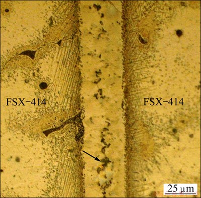
Fig. 8 Microstructure of TLP joints of FSX-414/MBF- 80/FSX-414 system made at 1323 K for 10 min
3.2.2 TLP bonding of FSX-414/MBF80/IN738
Microstructure of dissimilar joints of FSX-414/ MBF-80/IN738 system made at 1323 K for 10 min is shown in Fig. 9. As can be seen, the microstructures in the left and right halves are completely different. There are some intermetallics particles with different morphologies at both sides of the bond. In the FSX-414 half, these intermetallics are mostly needle-like, whereas they are almost spherical at the IN738 half. Also, the width of diffusion affected zone (DAZ) in IN738 half is more than that in the FSX-414 half. Distances between the positions of the eutectic islands and base-metal/interlayer boundary at the different points were measured and averaged on the two parts of the joints. They are 26.4 and 10.4 ��m for the IN738 and FSX-414 halves, respectively. The ratios of the distances are 2.53, 1.79 and 1.76 at bonding temperatures of 1323, 1373 and 1423 K, respectively.
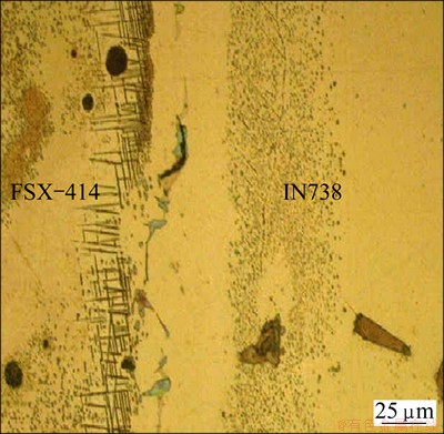
Fig. 9 Microstructure of TLP joints of FSX-414/MBF-80/ IN738 system made at 1323 K for 10 min
The simulated results for dissimilar TLP joints of FSX-414/MBF80/ IN738 made at 1323, 1373 and 1423 K are shown in Fig. 10, respectively. It is seen that curvatures of the graph at the top and bottom halves are different and asymmetric, unlike the similar joints. Confluence of the top and bottom graphs shows the location and time of the complete isothermal solidification. Figure 11 shows a comparison between the experimental and simulated results for the isothermal solidification time and the ratio of interface location. The predicted isothermal solidification time at the bonding temperatures of 1323, 1373 and 1423 K are 710, 350 and 185 s, respectively; whereas the experimental results are 600, 360-420 and 180 s, respectively at the same temperatures.
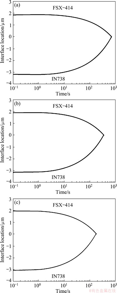
Fig. 10 Predicted solid/liquid interface location in TLP bonding of FSX-414/MBF80/ IN738 at bonding temperatures of 1323 K (a), 1373 K (b) and 1423 K (c)
When the bonding temperature decreases to1323 K, the differences between calculated and experimented results for isothermal solidification time and the solid/liquid interface location may rise to 10% and 13.5%, respectively.
The slope of the curves in Fig. 10 shows the solidification growth rate (speed of solid/liquid interface movement). Figure 12 shows the variation of these slopes with time for each half of the joint at various temperatures of 1323, 1373 and 1423 K. The solidification growth rate increases with time up to a certain value and then decreases in all curves. This is may be related to boron diffusion into the base metal, where with increasing boron concentration at the DAZ, the concentration gradient reduces and leads to reduction of solidification growth rate. Also, this rate increases with increasing the bonding temperature at each time. As the temperature rises, the diffusion coefficient and concentration gradient of boron increase and decrease, respectively. This variation results in increase of solidification growth rate, until the reduction of the gradient reaches a critical value. It is shown a considerable reduction in the melting point depressant element concentration gradient with increasing bonding temperature to being higher than the critical temperature can lead to a deviation of parabolic relationship between solid/liquid interface displacement and bonding time as well as reduction of isothermal solidification rate[7].
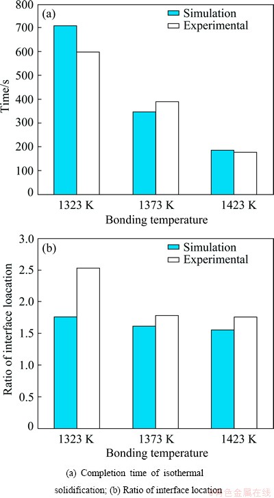
Fig. 11 Predicted and experimental results for TLP bonding of FSX-414/MBF80/ IN738 at different bonding temperatures of 1323, 1373 and 1423 K
4 Conclusions
The isothermal solidification process of the TLP joint of FSX-414/MBF80/IN738 was simulated by a new and simple model. A finite difference code was written and verified with the experiments and the other works. To obtain some required diffusion data, TLP bonding of FSX-414/MBF80/ FSX-414 was performed at different temperature and time under vacuum atmosphere. The simulated and experimental results showed that two solid/liquid interfaces meet each other closer to the FSX-414 than IN738 half. The rate of solid/liquid interface movement for both halves of the TLP bonding was calculated. Results showed that the growth rate at the IN738 half is more than that at the FSX-414.
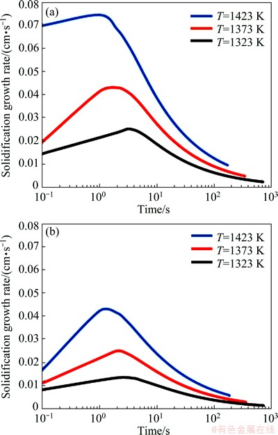
Fig. 12 Growth rate of solid/liquid interface movement for TLP bonding of FSX-414/MBF-80/IN738 system at IN738 (a) and FSX-414 halves (b)
Symbols
CSL
Equilibrium concentration of MPD at solid phase;
CLS
Equilibrium concentration of MPD at liquid phase;
Ds
Diffusion coefficient of boron in solid phase;
Dl
Diffusion coefficient of boron in liquid phase;
t
Time;
X
Location;
I(x)
Position of solid/liquid interface;
dt
Time step;

Next position of solid/liquid interface in the first joint half at the jth time step;

Next position of solid/liquid interface in the second joint half at the jth time step;

Concentration of boron in the liquid phase at the ith position and the jth time step in the first joint half;

Concentration of boron in the liquid phase at the ith position and the jth time step in the second joint half;

Concentration of boron in the solid phase at the ith position and the jth time step in the first joint half;

Concentration of boron in the solid phase at the ith position and the jth time step in the second joint half;
L1
Sum of liquid phase and solid phase thicknesses in the first joint half;
L2
Sum of liquid phase and solid phase thicknesses in the second joint half;
u1
Appropriate position of the liquid phase in the first joint half;
u2
Appropriate position of the liquid phase in the second joint half;
v1
Appropriate position of the solid phase in the first joint half;
v2
Appropriate position of the solid phase in the second joint half;
DA
Diffusion coefficient of boron in the liquid phase;
D1
Diffusion coefficient of boron in the solid phase in the first joint half;
D2
Diffusion coefficient of boron in the solid phase in the second joint half;
C1 A
Equilibrium concentration of boron in the liquid phase in contact with the solid phase in the first joint half;
C2A
Equilibrium concentration of boron in the liquid phase in contact with the solid phase in the second joint half;
C1
Equilibrium concentration of boron in the solid phase in contact with the liquid phase in the first joint half;
C2
Equilibrium concentration of boron in the solid phase in contact with the liquid phase in the second joint half;
N
Number of elements.
References
[1] GALE W F, BUTTS D A. Transient liquid phase bonding [J]. Science and Technology of Welding & Joining, 2004, 9: 283-300.
[2] OJO O A, RICHARDS N L, CHARTURVEDI M C. Effect of gap size and process parameters on diffusion brazing of Inconel 738 [J]. Science and Technology of Welding & Joining, 2004, 9: 209-220.
[3] DUVALL D S, OWCZARSKI W A, PAULONIS D F. TLP bonding: A new method for joining heat resisting alloys [J]. Welding Journal, 1974, 53: 203-214.
[4] GHONEIM A, OJO O A. Numerical modeling and simulation of a diffusion-controlled liquid�Csolid phase change in polycrystalline solids [J]. Computational Materials Science, 2011, 50: 1102-1113.
[5] KIM D U, KANG C Y, LEE W J. The effect of grain boundary on the dissolution of base metal into insert metal during TLP bonding of Ni-base superalloys [J]. Metals and Materials International, 1999, 5: 477-484.
[6] SAJJADI S A, NATEGH S, GUTHRIE R I L. Study of microstructure and mechanical properties of high performance Ni-base superalloy GTD-111 [J]. Materials Science and Engineering A, 2002, 325: 484-489.
[7] GHONEIM A, OJO O A. Microstructure and mechanical response of transient liquid phase joint in Haynes 282 superalloy [J]. Materials Characterization, 2011, 62: 1-7.
[8] EKRAMI A, MOEINIFAR S, KOKABI A H. Effect of transient liquid phase diffusion bonding on microstructure and properties of a nickel base superalloy Rene 80 [J]. Materials Science and Engineering A, 2007, 456: 93-98.
[9] LIU J D, JIN T, ZHAO N R, WANG Z H, SUN X F, GUAN H R, HU Z Q. Effect of transient liquid phase (TLP) bonding on the ductility of a Ni-base single crystal superalloy in a stress rupture test [J]. Materials Characterization, 2008, 59: 68-73.
[10] OHSASA K, SHINMURA T, NARITA T. Numerical modeling of the transient liquid phase bonding process of Ni using Ni-B-Cr ternary filler metal [J]. Journal of Phase Equilibria, 1999, 20: 199-206.
[11] NATSUME Y, OHSASA K, NARITA T. Phase-field simulation of transient liquid phase bonding process of Ni using Ni-P binary filler [J]. Meterials Transactions, 2003, 44: 819-823.
[12] ZHOU Y, GALE W F, NORTH T H. Modelling of transient liquid phase bonding [J]. International Materials Reviews, 1995, 40: 181-196.
[13] LI J F, AGYAKWA P A, JOHNSON C M. A fixed-grid numerical modelling of transient liquid phasebonding and other diffusion- controlled phase changes [J]. Journal of Materials Science, 2010, 45: 2340-2350.
[14] PADRONA T, KHANA T I, KABIRB M J. Modelling the transient liquid phase bonding behaviour of a duplex stainless steel using copper interlayers [J]. Materials Science and Engineering A, 2004, 385: 220-228.
[15] BAKHTIARI R, EKRAMI A, KHAN T I. The effect of TLP bonding temperature on microstructural and mechanical property of joints made using FSX-414 superalloy [J]. Materials Science and Engineering A, 2012, 546: 291-300.
[16] BAKHTIARI R, EKRAMI A. The effect of gap size on the microstructure and mechanical properties of the transient liquid phase bonded FSX-414 superalloy [J]. Materials and Design, 2012, 40: 130-137.
[17] BAKHTIARI R, EKRAMI A. Transient liquid phase bonding of FSX-414 superalloy at the standard heat treatment condition [J]. Materials Characterization, 2012, 66: 38-45.
[18] HEITJANS P, KARGER J. Diffusion in condensed matter: Methods, materials, models [M]. 2nd edition. Birkhauser, 2005.
[19] NISHIMOTO K, SAIDA K, KIM D, NAKAO Y. Transient liquid phase bonding of Ni-base single crystal superalloy CMSX-2 [J]. ISIJ International, 1995, 35: 1298-1306.
[20] GHONEIM A, OJO O A. Asymmetric diffusional solidification during transientliquid phase bonding of dissimilar materials [J]. Metallurgical and Materials Transactions A, 2012, 43: 900-911.
˲ʱҺ����������FSX-414/MBF80/IN738��ϵ�Ĺ�/Һ����λ�õ�Ԥ��
B. ABBASI KHAZAEI, G. ASGHARI, R. BAKHTIARI
Department of Materials Science and Engineering, Razi University, Kermanshah, 67147-54374, Iran
ժ Ҫ����������Ԫ��ַ�ģ��FSX-414/MBF80/IN738��ϵ����˲ʱҺ��(TLP)���ӵĵ������̹��̡���TLP����ģ�ͷ�Ϊ2���֣�������һ���ƶ���Һ/�̽���ģ�����о����ǡ�ʹ����ɢ���̶�ÿ���ֽ�ͷ����Ԥ�⣬ֱ���������̹��̽������ֱ�Ԥ������2���ֵĵ����������ʱ�䡢Ũ�ȷֲ����ߺ�/Һ����λ�ã���Ϊ��2���ֹ�/Һ����Ľ����ǵ������̵��յ㡣Ϊ�˻��һЩ��Ҫ����ɢ���ݣ��ڲ�ͬ�¶ȡ�ʱ�����������½���FSX-414/MBF80/ IN738��ϵ ��˲ʱҺ������ʵ�顣���������ʵ������Ԥ����һ�¡�
�ؼ��ʣ����ºϽ�����˲ʱҺ��(TLP)���ӣ�����λ�ã�ģ��
(Edited by Xiang-qun LI)
Corresponding author: B. ABBASI KHAZAEI; Tel: +98-8318369655; Fax: +98-8318231078; E-mail: biabkh@yahoo.com
DOI: 10.1016/S1003-6326(14)63154-X
Abstract: Isothermal solidification process of a dissimilar transient liquid phase (TLP) bonding of FSX-414/MBF80/IN738 system was simulated by finite difference method. The TLP joint model was divided into two parts and a moving liquid /solid interface model was used for the parts. Diffusion equations were solved for each half of the joints simultaneously up to the end of isothermal solidification. The completion time of isothermal solidification, concentration profiles and position of the solid/liquid interface for each half were calculated. The intersection of the solid/liquid interfaces of two halves was considered the end of isothermal solidification. To obtain some required diffusion data, TLP bonding of FSX-414/MBF80/IN738 was performed at different temperature and time under vacuum atmosphere. The calculated results show good agreement with the experimental results.
