
J. Cent. South Univ. Technol. (2011) 18: 2170-2175
DOI: 10.1007/s11771-011-0959-0![]()
Capillary force of a novel skew-grooved wick structure for micro heat pipes
WU Ju-hong(��պ�), TANG Yong(����), LU Long-sheng(½����)
Key Laboratory of Surface Functional Structure Manufacturing of Guangdong Higher Education Institutes,
School of Mechanical and Automotive Engineering, South China University of Technology,Guangzhou 510640, China
? Central South University Press and Springer-Verlag Berlin Heidelberg 2011
Abstract:
In order to improve the capillary force of grooved wick, a novel skew-grooved wick structure was proposed for micro heat pipes. Risen meniscus experiments were carried out to research the capillary force of the skew-grooved and rectangle-grooved wick and a comparison of capillarity between the two wick structures was explored. A theoretical capillary force model of skew-grooved wick structure was also developed to calculate its effective capillary radius by comparing with the rectangle-grooved wick. From the experimental results, the maximum capillary force of the skewed-grooved wick is 8.62% larger than that of the rectangle-grooved wick. From the theoretical analysis, because the skewed-grooved wick has a smaller effective capillary radius, its maximum capillary force is 8.64% larger than that of the rectangle-grooved wick. The results indicate that the skew-grooved wick provides larger capillary force than the rectangle-grooved wick.
Key words:
skew-grooved wick; micro heat pipe; capillary force; effective capillary radius��
1 Introduction
Micro heat pipe, which has the advantages of high heat transfer capacity, low thermal resistance and small structure, has been widely used in cooling of electronic components [1]. Generally, heat pipes consist of three components: shell, wick and end cover. The wick plays an important role in the heat transfer performances of heat pipes. Grooved and sintered wicks are the two main types of wicks. Compared with sintered wick, grooved wick has higher permeability, but smaller capillary force. Since COTTER [2] presented the concept of micro heat pipe (MHP) and established preliminary mathematical model in 1984, improving and optimizing the grooved wick structure of heat pipe has become the focus of heat pipe research. In 1995, DUNCAN and PETETERSON [3] established an analytical model of triangular cross-section micro heat pipe to calculate the heat transfer capacity and meniscus radius of the evaporator under the control of capillary limit of heat pipe. The physical and mathematical model for evaporator of triangular cross-section micro heat pipe was established by FAN et al [4]. WANG et al [5] studied the capillarity of micro grooves with rectangular cross-section theoretically and experimentally. CHEN et al [6] developed and analyzed a thermal model for a heat pipe with axially swallow-tailed microgrooves to predict the heat transfer capacity and total thermal resistance. In recent years, many kinds of grooved wick structures have been developed and studied. However, very few researchers optimize the wick structure for improving its capillarity.
The cyclic circulation of working liquid in heat pipes is driven by capillary force of wick [7-8]. The larger the capillary force, the better the heat pipes work. Investigating the capillary is an essential part of wick study for micro heat pipes. Usually, there are two methods to measure the capillary force of wick, named as bubble point test [9-10] and risen meniscus test [11]. Currently, the latter method has been widely used due to the convenience. However, the measurement of capillary force by visualization of the meniscus is not accurate because most of the working liquid is colorless and transparent. Especially, it is difficult to locate the meniscus of micro grooved wick. Infrared (IR) thermal imaging can make accurate and non-contact measurement of temperature field and it has been used to identify and locate the liquid meniscus of wick of micro heat pipes [12-14]. TANG et al [15] studied the capillary force of composite wick structures by IR thermal imaging and concluded that the capillary force of the composite wick is larger than that of the grooved and sintered wick.
Currently, the rectangle-grooved wick is widely used for grooved micro heat pipes, but it is also short in capillarity. Therefore, the purpose of this work is to improve the capillarity of grooved wick. A novel skew-grooved wick structure was proposed and the experimental equipment of the risen meniscus that was set up by TANG et al [15] was adopted to determine the capillary force of the skew-grooved wick.
2 Risen meniscus experiment
2.1 Skew-grooved wick structure manufacturing
The oil-filled high-speed spinning [16] with multi-tooth tool was adopted to manufacture the skewed micro-grooved wick. This processing was feasible and simple, which could be in mass production. These skewed micro-grooves had large depth-to-width ratio and were uniformly distributed inside copper tube, as shown in Fig.1. Figures 1(a) and 1(b) show the SEM photographs of the skewed micro-groove structure; Fig.1(c) shows the SEM photograph of the inner wall structure of the skewed tooth micro-groove. There was a broken tooth and a large tooth in Fig.1(a). The large tooth was due to the tool processing method, and it was inevitable. The broken tooth was an error in processing, which was accidental and avoidable. However, in this work, the samples for the experiments were the half of tubes without these bad teeth. Therefore, the experimental effect was not affected by the large tooth and broken tooth.
In this work, two kinds of wick structure samples were made for comparison. One was the novel skew- grooved wick, and the other was a rectangle-grooved wick. Their schematic diagrams are shown in Fig.2 and Fig.3, respectively. There were three samples for each structure for the risen meniscus experiments. All the samples had the same dimensions, with 6 mm in radius, 0.32 mm in depth of grooves and 55 teeth, as shown in Table 1.
2.2 Experimental equipment and meniscus locating analysis
In order to determine the capillary force of wick structures, an equipment of risen meniscus experiment that was set up by TANG et al [15] was adopted, as shown in Fig.4.
According to the blackbody radiation law [11], the infrared radiation characteristics of an object could be obtained by its material emissivity. Based on this, the measured temperature data are depended on the emissivity selected. In other words, if we use the emissivity of one material as the basis to measure the temperature of another material, an error occurs. Therefore, due to the infrared emissivity difference between copper and ethanol, despite the fact that the true temperature distribution may be isothermal, different temperature distributions between the sample and ethanol were displayed in IR thermal images.
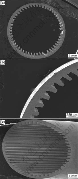
Fig.1 SEM photographs of skewed-grooved wick structure: (a) Whole wick; (b) Skewed micro-groove; (c) Inner wall
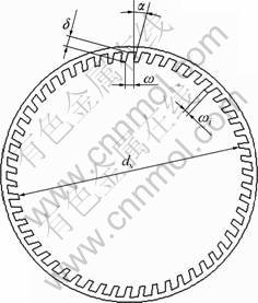
Fig.2 Schematic diagram of skew-grooved wick structure
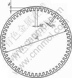
Fig.3 Schematic diagram of rectangle-grooved wick structure
Table 1 Samples parameter and specifications

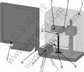
Fig.4 Schematic diagram of risen meniscus test apparatus: 1��Black cover; 2��Vertically adjusting device; 3��Sample fixing device; 4��Wick; 5��PC; 6��PLC controller; 7��IR camera; 8��Hole; 9��Reservoir with ethanol
In these experiments, a FLIR ThermaVisionTM A20 M IR camera was used with a thermal sensitivity of 0.02 K at 17 ��C and an accuracy of 1% for temperatures below 150 ��C of the full scale. The outer surface of the sample was painted black to maintain a uniform emissivity. During the risen meniscus experiments, working liquid raised in a wick. The following assumptions were given: 1) steady-state laminar flow in the wick, 2) uniform saturation with liquid along the wetted length, and 3) neglecting inertial effects and evaporation of liquid [12].
The meniscus could be accurately located as follows. A measuring line was drawn along the sample from the fixing device to the dipping end. It stood for the sample and its length had been measured before the sample was dipped into ethanol. A locating point was added in the measuring line. As this point moved vertically along the measuring line, the vertical line moved along the temperature distribution curve until arriving at the inflection point. The position of this inflection point stood for the meniscus. The height of the point could be calculated. Thus, the wetted height, marked as H, was obtained [12]. The higher the meniscus rises, the larger the capillary force of the wick is, which means that the larger the value of H is, the larger capillary force the wick provides. Besides, the wetted height over time during the whole visualization process could be accurately obtained. Thus, the rising velocity of wetted height could also be studied.
3 Results and discussion
3.1 Experimental results
Through the software of ThermalCAM Researcher by FLIR SYSTEMS, the meniscus rising recording of samples by IR thermal imaging camera could be analyzed and processed. Figure 5 shows the meniscus rising process of the skew-grooved wick structure in 1 min. The higher the meniscus rises, the larger the value of H is, and the larger capillary force the wick provides.
During the experiments, two kinds of samples are tested for comparison. One is the skew-grooved wick structure, and the other is the rectangle-grooved wick structure. Analyzing the recordings of the two wicks by the above means respectively, the results are obtained, as shown in Fig.6.
For the first 10 s, the wetted height and the rising velocity of the skewed-grooved wick structure are smaller than those of the rectangle-grooved wick structure. This is because the skewed angle of the skew-grooved wick structure causes smaller soakage. In the initial time after the skew-grooved wick has been dipped into ethanol, the liquid rises along the skew-grooves slowly fighting the resistance of skewed angle. Grooves in both wicks provide capillary force for liquid rising. As the liquid rises, the rising velocity is reduced gradually. During this period, the difference of capillary force between these two kinds of wicks plays an important role in liquid rising. From Fig.6, it can be seen that the wetted height and the rising velocity of the skew-grooved wick are larger than those of the rectangle-grooved wick after 10 s. Obviously, the reason is that the driving force of the skew-grooves is larger than that of the rectangle-grooves.

Fig.5 Meniscus rising process of skew-grooved wick structure in 1 min: (a) t=0 s; (b) t=10 s; (c) t=20 s; (d) t= 30 s; (e) t=40 s; (f) t=50 s; (g) t=60 s

Fig.6 Comparison between skew-grooved and rectangle- grooved wicks
After 50 s, the meniscus rising of two wicks come into steady stage. From Fig.6, the eventual wetted height of skew-grooved wick is larger than that of the rectangle- grooved wick by 8.62%. Therefore, the skew-grooved wick provides larger capillary force than the rectangle- grooved wick. And experimental results demonstrate that the maximum capillary force of the skew-grooved wick is larger than that of the rectangle-grooved wick by 8.62%.
It is safe to say, in fact, that the skewed grooves make the wick into semi-closed state, which can increase the depth-to-width ratio of the grooved wick. According to the capillary force theory, this structure can improve the capillary force of the grooved wick for micro heat pipes. Although in the beginning the skew-grooved wick soaks slowly due to its semi-closed state, during the meniscus rising until the steady stage, the capillary force of the skew-grooved wick is increased markedly. Therefore, the skew-grooved wick structure can improve the capillary force of the grooved wick for micro heat pipes.
3.2 Theoretical analysis
Generally, the maximum capillary force varies inversely with effective capillary radius as [17]
![]() (1)
(1)
where ��Pcap,max is the maximum capillary force, �� is the surface tension of liquid and rc is the effective capillary radius.
Effective capillary radius rc is defined as: equating 2/rc to the maximum value of (1/R1+1/R2) of wick structure [17-18]. Here, R1, R2 are the main radii of curvature of the meniscus of wick structure. For the skew-grooved wick structure, as shown in Fig.7, it can be obtained:
R1=�� (2)

Fig.7 Diagram of effective capillary radius calculation
Meanwhile, because of the skewed angle ��, the other main radius can be expressed as
![]() (3)
(3)
where �� is the width of grooves and �� is the skewed angle of the grooved wick.
According to the definition of effective capillary radius rc, the following calculation procedure can be made from Eq.(2) and Eq.(3):
![]() (4)
(4)
Thus, form Eq.(4), it can be obtained:
![]() (5)
(5)
Similarly, for the rectangle-grooved wick structure, its effective capillary radius rc can be obtained by
![]() (6)
(6)
However, in the rectangle-grooved wick structure, there is no skewed angle. That is to say, ����=0��. So, it can be obtained:
![]() (7)
(7)
According to Eq.(5) and Eq.(7), it can be obviously concluded that the effective capillary radius of the skew- grooved wick structure is smaller than that of the rectangle-grooved wick.
A comparison of effective capillary radius rc between the skewed-grooved wick with a skewed angle of 23�� and the rectangle-grooved wick can be obtained, just as shown in Fig.8. The effective capillary radius of the skew-grooved wick structure is smaller than that of the rectangle-grooved wick structure, that is, the maximum capillary force of the former is larger than that of the latter one.

Fig.8 Comparison of effective capillary radius rc between two wick structures
Moreover, according to Eq.(1), Eq.(5) and Eq.(7), the increased percentage �� of the maximum capillary force of the skewed-grooved wick is obtained as
![]() (8)
(8)
For the skew-grooved wick with a skewed angle of 23�� used for the experiments, there is
![]()
So, its maximum capillary force is larger than that of the rectangle-grooved wick by 8.64%.
Therefore, the experimental results agree with the above theoretical analysis. The skew-grooved wick provides larger capillary force than the rectangle-grooved wick because of the smaller effective capillary radius. And the maximum capillary force of the skew-grooved wick is larger than that of the rectangle-grooved wick by 8.62%.
4 Conclusions
1) The skew-grooved wick structure is presented for micro heat pipes. The skewed grooves make the wick into semi-closed state, which can increase the capillary force of the grooved wick. By comparing the skew-grooved wick and the rectangle-grooved wick experimentally, the 8.62% increase of capillary force of the skewed-grooved wick can be obtained.
2) According to the theoretical model of the skew- grooved wick structure, its effective capillary radius can be given as rc=��cos�� and the increased percentage �� of the maximum capillary force of the skewed-grooved
wick can be obtained as ![]() where �� is the
where �� is the
width of grooves and �� is the skewed angle of the grooved wick. The maximum capillary force of skew-grooved wick is 8.64% larger than that of the rectangle-grooved wick because of the smaller effective capillary radius.
3) Theoretical analysis and experimental results both indicate that the skew-grooved wick provides larger capillary force than the rectangle-grooved wick. The skew- grooved wick structure has a good capillarity and can be applied to micro heat pipes.
4) Future work is needed to establish the theoretical model of the liquid flow in the skew-grooved wick. Besides, the theoretical and experimental investigation of micro heat pipes with skew-grooved wick structure will be carried out.
References
[1] VASILIEV L L. Micro and miniature heat pipes�Celectronic component coolers [J]. Applied Thermal Engineering, 2008, 28(4): 266-273.
[2] COTTER T P. Principles and prospects for micro heat pipes [C]// Proceedings of 5th International Heat Pipe Conference. Tsukuba, Japan, 1984: 328- 335.
[3] DUNCAN A B, PETETERSON G P. Charge optimization for a triangular-shaped etched micro heat pipes [J]. Thermophysics and Heat Transfer, 1995, 9: 365-368.
[4] FAN Chun-li, QU Wei, SUN Feng-ri, YANG Li, MA Tong-ze. Status and recent progress of research on micro/miniature heat pipes [J]. Chinese Journal of Electron Devices, 2004, 27(1): 211-216.
[5] WANG H J, TSAI H C, CHEN H K, SHING T K. Capillarity of rectangular micro grooves and their application to heat pipes [J]. Tamkang Journal of Science and Engineering, 2005, 8(3): 249-255.
[6] CHEN Yong-ping, ZHU Wang-fa, ZHANG Cheng-bin, SHI Ming-heng. Thermal characteristics of heat pipe with axially swallow-tailed microgrooves [J], Chinese Journal of Chemical Engineering, 2010, 18(2): 185-193.
[7] BUTT H J, KAPPL M. Normal capillary forces [J]. Advances in Colloid and Interface Science, 2009, 146(1/2): 48-60.
[8] LI Jin-wang, ZOU Yong, CHENG Lin. Experimental study on capillary pumping performance of porous wicks for loop heat pipe [J]. Experimental Thermal and Fluid Science, 2010, 34(8): 1403-1408.
[9] CHEN S W, HSIEH J C, CHOU C T, LIN H H, SHEN S C, TSAI M J. Experimental investigation and visualization on capillary and boiling limits of micro-grooves made by different processes [J]. Sensors and Actuators A: Physical, 2007, 139(1/2): 78-87.
[10] BOUKHANOUF R, HADDAD A, NORTH M T, BUFFONE C. Experimental investigation of a flat plate heat pipe performance using IR thermal imaging camera [J]. Applied Thermal Engineering, 2006, 26(17/18): 2148-2156.
[11] DAS A, CHATTERJEE A K, BASU S P. A method of measuring capillary rise in a heat pipe [J]. International Journal of Heat and Mass Transfer, 1985, 28(10): 1959-1960.
[12] ADKINS D R, DYKHUIZEN R C. Procedures for measuring the properties of heat pipe wick materials [C]// Proceedings of the 28th Intersociety Energy Conversion Engineering Conference. Washington D C, 1993: 911-917.
[13] KAPLAN H. Practical applications of infrared thermal sensing and image equipment [M]. USA: Georgia Institute of Technology, 1993: 38-43.
[14] ZHANG Feng, PENG Jin, GENG Jiao, Wang Zhi-xiang, ZHANG Zhi-bing. Thermal imaging study on the surface wave of heated falling liquid films [J]. Experimental Thermal Fluid Science, 2009, 33(3): 424-430.
[15] TANG Yong, DENG Da-xiang, LU Long-sheng, PAN Min-qiang, WANG Qing-hui. Experimental investigation on capillary force of composite wick structure by IR thermal imaging camera [J]. Experimental Thermal and Fluid Science, 2010, 34(2): 190-196.
[16] TANG Y, CHI Y, CHEN J C, DENG X X, LIU L, LIU X K, WAN Z P. Experimental study of oil-filled high-speed spin forming micro-groove fin-inside tubes [J]. International Journal of Machine Tools and Manufacture, 2007, 47(7/8): 1059-1068.
[17] IVANOVSKII M N, SOROKIN V P, YAGODKIN I V. The physical principles of heat pipes [M]. Oxford: Oxford University Press, 1982: 52-61.
[18] CHI S W. Heat pipe theory and practice [M]. New York: McGraw- Hill, 1976: 40-48.
(Edited by YANG Bing)
Foundation item: Project(U0834002) supported by the Key Program of NSFC-Guangdong Joint Funds of China; Project(51005079) supported by the National Natural Science Foundation of China; Project(2009ZM0121) supported by the Fundamental Research Funds for the Central Universities in China; Project(LYM09024) supported by the Training Program for Excellent Young Teachers with Innovation of Guangdong University, China
Received date: 2010-10-21; Accepted date: 2011-05-23
Corresponding author: TANG Yong, Professor, PhD; Tel: +86-20-87114634; E-mail: ytang@scut.edu.cn
Abstract: In order to improve the capillary force of grooved wick, a novel skew-grooved wick structure was proposed for micro heat pipes. Risen meniscus experiments were carried out to research the capillary force of the skew-grooved and rectangle-grooved wick and a comparison of capillarity between the two wick structures was explored. A theoretical capillary force model of skew-grooved wick structure was also developed to calculate its effective capillary radius by comparing with the rectangle-grooved wick. From the experimental results, the maximum capillary force of the skewed-grooved wick is 8.62% larger than that of the rectangle-grooved wick. From the theoretical analysis, because the skewed-grooved wick has a smaller effective capillary radius, its maximum capillary force is 8.64% larger than that of the rectangle-grooved wick. The results indicate that the skew-grooved wick provides larger capillary force than the rectangle-grooved wick.
